
The LPF process is uses for treatment of copper ores in which part or all of the copper occurs in oxidized form presents a problem for recovery. Sulphidization of the oxidized copper minerals using sodium sulphide or sodium sulphydrate is sometimes effective to render the minerals floatable, but generally sulphidization techniques produce low recoveries. Many oxidized copper ores do not react to sulphidization and other means must be used.
What is the LPF Flowsheet
The flowsheet in this study was designed to treat a semi-oxidized ore in which the oxidized (non-sulphide) copper minerals are predominantly chrysocolla and malachite with the sulphide copper meneral being mainly chalcopyrite. The gangue is siliceous so no excessive acid-consuming carbonate gangue minerals are present. Approximately 40% of the total copper occurs in non-sulphide form.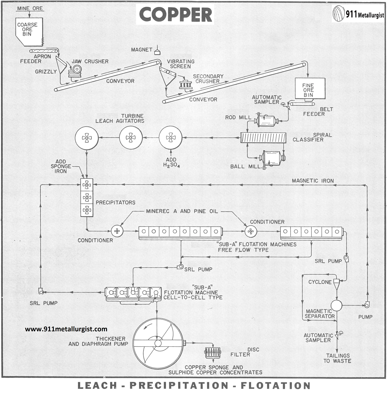
Metallurgical tests conducted on the ore showed that sulphidization was ineffective to recover a significant part of the oxidized copper. However, the leach- precipitation-flotation process, commonly referred to as LPF, was shown to be economically feasible. Basically, the L-P-F process consists of dissolving the oxidized copper minerals with sulphuric acid and precipitating the copper as a metallic sponge which responds to flotation. The advantage of this process is that all phases of treatment are performed in the ore pulp which eliminates the necessity of separating the leach solution from the solids as required for conventional leaching. Another advantage: sulphide copper can be saved by the same flotation step, thus avoiding a separate sulphide circuit.
CRUSHING AND GRINDING CIRCUIT
Two-stage, open circuit crushing is shown on the flowsheet since a rod mill is incorporated in the grinding circuit. This arrangement is often preferable to a three-stage crushing circuit because of lower costs and the ability to handle wet, sticky ores. The rod mill discharge, which is essentially minus 10-mesh, goes to a classifier to remove finished material. The classifier sands are ground in a ball mill in closed circuit with the same classifier.
LEACHING CIRCUIT
The classifier overflow (— 65 mesh) at approximately 25% solids flows to the acid- proof leach agitators equipped with rubber – covered Turbine Type Propellers. Sulphuric acid is added to the feed of the first agitator in quantities sufficient to produce a pH of about 1.5 to 2.0. No further additions of acid are required in the agitators. The pH of the pulp as it discharges from the third agitator is between 2.5 and 3.0. The contact time for dissolution is approximately 45 minutes.
The Turbine Type Propeller produces an axial pulp flow in the agitators and is ideal for acid leaching applications. Horsepower and maintenance costs are a minimum.
COPPER PRECIPITATION
The precipitation of soluble copper from the leach pulp is accomplished using metallic iron as the precipitant. This step can be performed using burned and shredded cans in a slowly revolving precipitation drum through which the pulp flows or by means of finely divided sponge iron ( — 35 mesh) which is contacted with the pulp in Precipitators. The use of sponge iron is shown in the flowsheet.
Precipitation of the copper is completed in about 10-15 minutes. The oxidation-reduction reaction between copper sulphate and metallic iron increases the pH of the pulp to about 3.5-4.0. The copper is precipitated as a very fine copper sponge. An excess of the sponge iron is used so that re – solution of copper is avoided. This excess iron carries through the flotation circuit and is recovered by magnetic separation of the final flotation tailing and reused.
COPPER CEMENT FLOTATION
The precipitated sponge copper and the insoluble copper sulphide minerals are recovered from the pulp using conventional flotation. The pulp is conditioned with Minerec A as a collector and pine oil as a frother preparatory to flotation. The tailing from the first bank of flotation cells is conditioned with additional amounts of the reagents and more copper recovered by a scavenger stage of flotation. “Sub-A” Flotation Cells of the free-flow design are employed for the two stages of flotation.Conditioning is a very essential step to achieve maximum copper recovery. The Conditioners, which allow positive recirculation of pulp, are ideal for this job.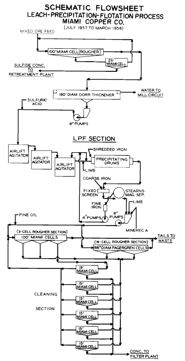
The pH of the flotation feed is quite critical for optimum froth conditions and copper recovery. Neither too low nor too high a pH is desirable. A pH of 4.0 (plus or minus 0.5) represents the most effective pH for flotation in most cases.
The rougher and scavenger copper concentrates are combined and cleaned twice in a “Sub – A” Flotation Machine of cell-to-cell design for production of the final copper concentrate. The cleaner tailing is returned to the first precipitation agitator.
THICKENING AND FILTRATION
The final copper concentrate (sponge copper and sulphide copper) is thickened and filtered. The dewatered concentrate (10% moisture) is then shipped to a copper smelter.
SPONGE IRON PRODUCTION
The quality of sponge iron employed in the LPF process is important since it relates to the precipitation efficiency and sponge iron consumption. Normally a 40 to 60% metallic iron content in the sponge iron is acceptable with the higher grade being preferred. Sponge iron is produced by roasting pyrite and reducing the iron oxide calcine at temperatures in excess of 1500°F. with coal in a Bruckner revolving furnace followed by cooling to 150°F. in an enclosed Baker cooler. The resulting sponge product is ground to —35 mesh for use in the precipitation circuit of the L-P-F process. The sulphur dioxide gas from the initial pyrite roasting step is converted to sulphuric acid for use in the leaching.
ACID-PROOF EQUIPMENT
All equipment in contact with the acid pulps in the L-P-F process must be of acid-resistant construction. Stainless steel, rubber, wood, and special plastic compounds are commonly employed in the fabrication of the acid wetted parts.
Other ramifications of the L-P-F process are possible to meet the requirements of a particular ore.
Summarize the LPF
Description of the Ore
A semi-oxidized copper ore containing chrysocolla and malachite as the non-sulphide copper minerals associated with chalcopyrite in a siliceous gangue.
Assay of Ore, Approximate
Total copper……………………………………………………..1.64%
Non – Sulphide copper……………………………………….0.70%
Sulphide copper………………………………………………..0.94%
Method of Process
Leach-Precipitation-Flotation (LPF)
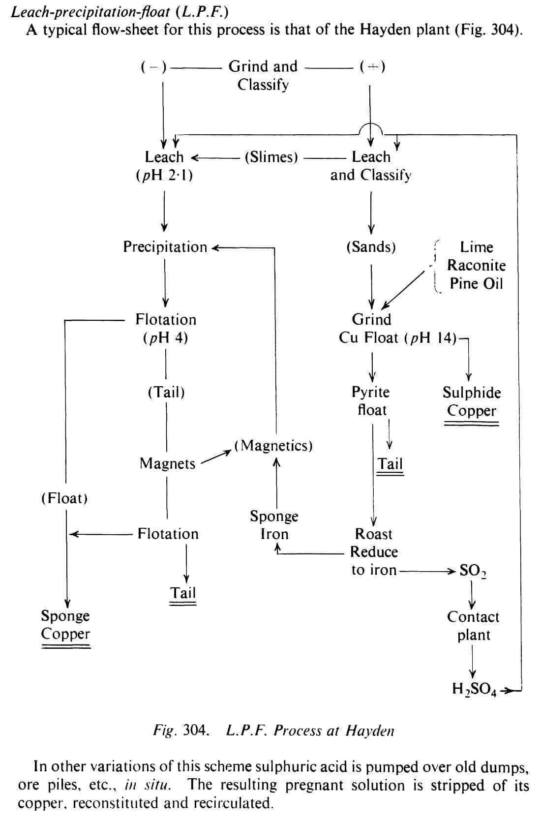
In other variations of this scheme sulphuric acid is pumped over old dumps, ore piles, etc., in situ. The resulting pregnant solution is stripped of its copper, reconstituted and recirculated.
The use of sulphuric acid in the L.P.F. process has the further effect of cleaning partially oxidised sulphide surfaces during treatment with sulphuric acid, following which flotation with xanthate may be improved.
At Inspiration, Arizona, the old process called for leaching followed by electrolysis. With impoverishment of the mine at depth together with an increase in the proportion of sulphidic copper the old acid ferric sulphate process which took nine days has been dropped. Instead, leach contact with straight acid for four days now deals with the oxidic copper, leaving clean sulphides to be recovered by flotation. Ray (Kennecott) has developed a LPF flow-sheet for recovering oxidic copper. The values include chrysocolla, cuprite, malachite, tenorite, and native copper. The carbonate, silicate, and sulphate are the main objects of attack. Copper is got into solution by standard leaching methods. The residue is reground, given froth flotation to recover the sulphide copper, and then refloated for its pyrite. This pyrite is calcined, producing SO2, which after reaction to H2SO4 is used for leaching. The ash is reduced with coal to yield finely divided iron. This iron is circulated through the precipitation plant and is then removed by flotation as a copper-iron froth, any iron not caught at that stage being picked up, if needed, by magnetic separation of the tailing.
LPF as a method of treating mixed sulphide-oxidic copper ores was developed from tests started in Arizona in 1929. “Oxidic” includes copper oxides, carbonates and silicate. The original full-scale operation (1934— 1943) and a revived form (1957-1959) have been reviewed by Bean34 35. In the finalised process the sulphide minerals were first floated and the tailings, in which chrysocolla was the dominant copper value, were thickened and leached with sulphuric acid in air-lift agitators. Copper was then precipitated during passage of the “pregs” over de-tinned and shredded cans agitated in wooden drums, and floated. At Hayden it was found that there should be an excess of minus 35 mesh powdered iron in the secondary (acid) stage of flotation. Any unconsumed iron was removed by magnetic separation applied to the scavenger tailings. At Rosita, Nicaragua, highly refractory ores are treated by LPF 36 The copper is precipitated on shredded iron, screened to pass 6 mesh and floated with Minerec A and Aerofloat 25. Three types of precipitate must be allowed for—a readily floated fluffy cement copper, a reluctant hard and granular cement, and copper-plated iron particles giving a low-grade but payable concentrate.
Source: This article is a reproduction of an excerpt of “In the Public Domain” documents held in 911Metallurgy Corp’s private library.