
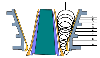
On left is a showing of the “standard gyratory with straight concaves” is a section through any vertical, radial plane in the crushing chamber of one of the intermediate sizes of the crusher. In order to understand the crushing action in such a chamber it is helpful to consider the process as though each step took place in an orderly, and “ideal” fashion. It is hardly necessary to add that the action never does take place in just that fashion; nevertheless the concept is fundamentally a correct one, and the average performance of the crusher follows the pattern so closely that it is possible to predict, within surprisingly close limits; what any particular design of crusher will do.
Lets start out by visualizing the crushing chamber filled with a tractable material which will act just the way we want it to, with a head of material (choke-feed) above the receiving opening so that no unsurge of load will occur during the closing stroke of the crusher head. Now, consider any horizontal plane through this body of material as, for example, the plane at the receiving opening, represented by line “O” in the diagram. The crusher head is at the moment in the close-side position.
As the head recedes on its opening stroke, the body of material moves downward; until, at the end of the stroke, the plane has moved to position “1.” Note that the length of line “1″ from concave to open-side head position, is the same as that of line “O” from concave to close-side head position.
On the next closing stroke line “1” is compressed by the amount of the bead movement at that level, and on the next opening stroke it moves down to position “2” and so on flown through the chamber, until it becomes short enough to pass through the open-side discharge setting.
We can just as readily visualize the process as being the movement of the trapezoidal areas enclosed by each adjacent pair of horizontal lines and the two crushing faces. Better still, we can consider it as the movement of annular volumes whose cross-sections are the areas just mentioned. This latter conception is essential in visualizing the action of non-choking concaves and crushing chambers.
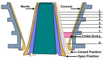
In the diagram, the broken line through the centre of the crushing chamber is the line-of-mean-diameters of the compacted areas. When the profiles of both crushing fact’s are straight lines, as in the case under consideration, this mean-diameter line is also straight, and its slope depends upon the relative tapers of the head and concaves. When the line approximately parallels the centre-line of the crusher, which is also the case for the diagram we are examining, the theoretical action closely approximates that of the jaw crusher of similar cross-sectional proportions. Practically, however, the gyratory will have some advantage over the jaw, as regards freedom from choking, because the spider arms of the gyratory pre-vent a complete filling of the crushing chamber at the top. When the line slopes away from the crusher centre-line at its lower end the characteristics change quite definitely in favour of the gyratory, as will be seen.
A variable effort is required between the top and bottom of the chamber to crush particles. This may be understood by comparing the mantle and concaves to a nutcracker. Imagine the spider as the nutcracker’s fulcrum point, and your hand as applying power similar to that applied by the eccentric at the base of the main-shaft. The closer to the fulcrum point that the nut is initially cracked, the less power you have to apply with your hand. In the same manner the crushing effort, and demand for power, becomes greater as the centre of gravity of the rock mass moves downward in the crusher.
Gyratory Crushers are heavy-duty machines run in open circuit (sometimes in conjunction with scalping screens or grizzlies). They handle dry run-of-mine feed material as large as 1 m. There are two main types of primary crushers-gyratory crushers and jaw crushers. Gyratory crushers are the most common for new operations.
Secondary crushers are lighter-duty and include cone crushers, roll crushers, and impact crushers. Generally, the feed to these machines will be less than 15 cm, and secondary crushing is usually done on dry feed. Cone crushers are similar to gyratory crushers, but differ in that the shorter spindle of the cone is not suspended but is supported from below by a universal bearing. Also, the bowl does not flare as in a gyratory crusher. Cone crushers are generally the preferred type of secondary crusher because of their high reduction ratios and low wear rates. However, impact crushers are used successfully for relatively nonabrasive materials such as coal and limestone. Frequently, size reduction with secondary crushers is accomplished in closed circuit with vibrating screens for size separation.
The gyratory crusher is used as a primary and secondary stage crusher. The cone crusher is used as a secondary, tertiary, and quaternary crusher. The action of a typical gyratory-type crusher is illustrated above. In gyratory crushers the crushing process comprises reduction by compression between two confining faces and a subsequent freeing movement during which the material settles by gravity until it is caught and subjected to further compression and again released. The particles are subjected to maximum breaking forces when they are on the side with the minimum gape.
Gyratory crushers work on a similar principle to jaw crushers but have a circular gap. Rock is compressed between a static conical bowl and a concave mantle which oscillates about the central axis. These are generally designed for primary crushing in large-scale rock crushing applications up to 6000 t/h. Typically a mining haul truck will empty its load into the gyratory crusher and reduce the feed with a top-size of up to a few meters down to below around 250 mm.