

A cyclosizer, in principle, is an “old sizing machine” allowing size analysis of sub-sieve size (-38 micron).
One of the most widely used methods of sub-sieve sizing in modern mineral-processing laboratories is the Warman Cyclosizer which is extensively used for routine testing and plant control in the size range 8 – 38 micron for minerals of specific gravity similar to quartz (s.g. 2.7) and down to 4 micron for particles of high specific gravity, such as galena (s.g. 7.5).
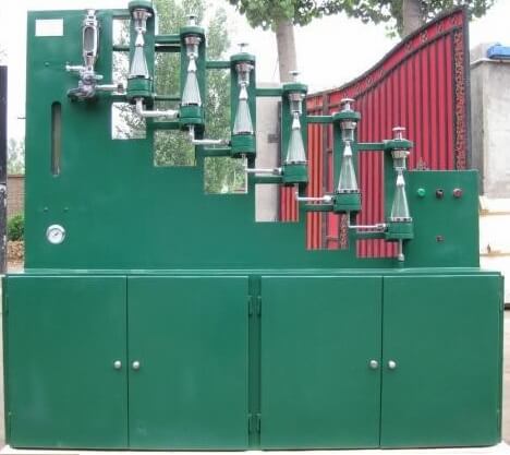
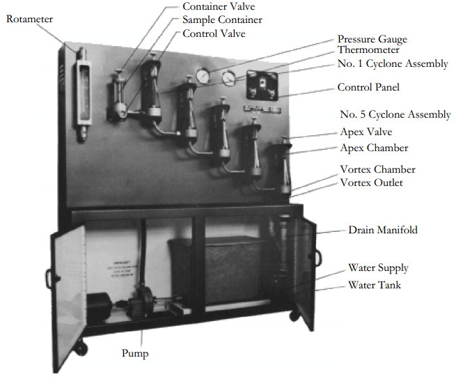
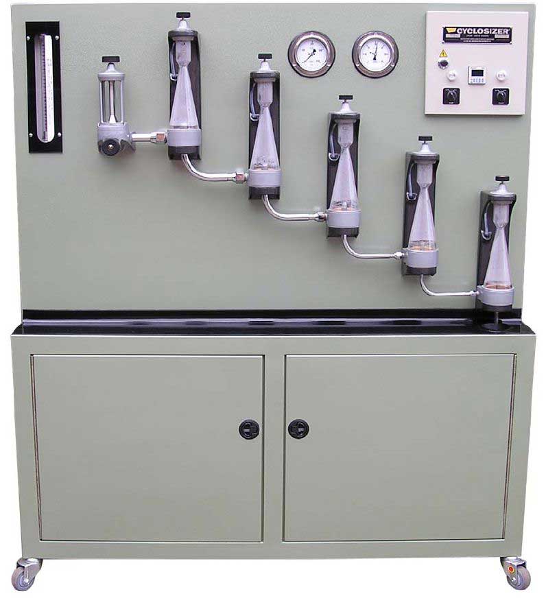
A Cyclosizer price varies upon where or who you buy it from or, the ‘Brand Manufacturer‘: One Cyclosizer, capable of effective size classification in the 8 to 50 micron range (for quartz), complete with 5 glass body cyclones, internal pumps, piping, valves, gauges, 0-60 minute timer, 230V/50-60 Hz operation, contained in a sheet metal cabinet finished inside with white enamel and outside with green enamel. Doors in the front of the cabinet allow access to the feed tank and pump.
Shipping Wt: 880 lbs. Shipping Volume: 75 Ft3 >> Cyclosizer price: $45000 to $73000
Transport cost is extra as always. Delivery time is 4 to 16 weeks depending on the Brand.
The cyclosizer, consists of five unit cyclones arranged in a series such that the overflow of one unit is the feed to the next unit. The individual units are inverted in relation to conventional cyclone arrangements, and at the apex of each, a chamber is situated so that the discharge is effectively closed. Water is pumped through the unites at a controlled rate, and a weighed sample of solids is introduced ahead of the cyclone. The cyclosizer is manufactured to have definite limiting separation sizes at standard values of the operating variables, water flow rate, water temperature, particle density and elutriation time.
The tangential entry into the cyclones induces the liquid to spin, resulting in a portion of the liquid, together with the faster-settling particles, reporting to the apex chamber, while the remainder of the liquid, together with the slower settling particles is discharged through the vortex outlet, and into the next cyclone in the series. 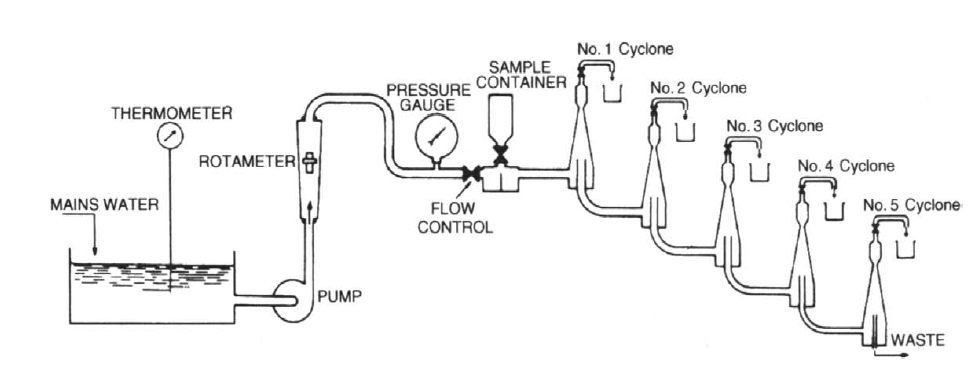 There is a successive decrease in the inlet area and vortex outlet diameter of each cyclone in the direction of the flow, resulting in a corresponding increase in inlet velocity and an increase in the centrifugal forces within the cyclone, resulting in a successive decrease in the limiting particle-separation size of the cyclones. If you can read Spanish, this is a pretty good cyclosizer principle and operation paper.
Manufacturer
Equipment
- Cyclosizer
- -38 micron sized material
- Beakers
Cyclosizing Procedure
- Switch on both power points at wall and check hot and cold water main valves open.
Also check hot water control valve open. Also check that automatic water temperature
(23° ± 2°C) is correctly set and operational. - Plug in sample chamber.
- Switch on pump.
- Open rotameter valve.
- Close pot discharge valves (after removing air).
- Check the room temperature.
- Set timer to five minutes (Feed Cycle) and open sample chamber slowly to feed particles within five minutes.
- After feed time (five minutes) buzzer sounds. Set timer to separation time (20 minutes) and adjust rotameter flow down to 185 (as for 5).
- After separation time (20 minutes) buzzer sounds; adjust rotameter flow up to 200.
- Discharge CS5 pot product in to 1 litre beaker and return plastic hose to drain.
- Repeat discharge of CS4, CS3, CS2 and CS1 in that order as for (10).
- Shut off rotameter valve.
- Open all valves.
- Switch off pump.
- Switch off power points at wall.
- Dry, weigh and pack each fraction.
- Collect –5 micron fraction and determine requirement for further separation (ie.beaker decantation).
- Send each fraction for assaying.
- Report the results in table form.
 If separation time, water temperature, flow rate or s.g. of solids (2.7) are different to above, correction factors will be required for cyclone cut sizes.For this machine cut sized on quartz are in Microns: C1=45 C2=34 C3=24 C5=16 C6=11.5
Precaution
Read the Warman Cyclosizer instruction manual or cyclosizer operating manual carefully and inspect the cyclosizer, noting all the component parts and how to operate them. Do not operate the machine until you are sure/trained with the correct procedure.
The article describes a general vision about the use of the Cyclosizer used mainly for the realization or experimental tests of metallic and non metallic minerals in the processing of minerals such as: gold bearing minerals and dolomite minerals, respectively. The cyclosizer is an elutriator that separates a specimen in specifically sized fractions using a technique that depends on the forces produced by the relative speed of the particles and the elutriation fluid. It is different from a conventional elutriation where the elutriation action takes place in a hydraulic cyclone where the fluid is spinning and the centrifugal forces are acting on the particles due to the gravity. The fluid models in the cyclone are stable and the changes in the condition of the atmosphere are not as critical as in the case of the conventional processing for elutriation. Also, the high cutting forces that are
developed in the cyclone exceed any natural tendency in order to floccule the fine material and assure an excellent disposition of the particles.
I found this great cyclosizer stuff.
Cyclosizing Procedure – How to use a Cyclosizer
APPARATUS
- Cyclosizer.
- 250 mL beaker
- 1 L beakers
- Stirrer and stirring bar
- Ultrasonic container
- Wash bottle
- 150 mm sharkskin filter paper
PROCEDURE
Samples for the cyclosizer should be finer than 270 mesh (53 μm). If the sample is coarser than 270 mesh, screen analysis should be employed. Samples’ specific gravity should have already been determined. (Refer to specific gravity determination procedure)
- Stir 30-50 g of sample with about 100 mL of tap water in a 250 mL beaker. If the solids are not dispersed, put the beaker in an ultrasonic container for 15 minutes.
- Ensure the pump is off and the control valve is closed.
- Remove the sample container from its holder by turning the container until one of the metal sides is facing outward and pull straight upward.
- Open fully the valve on the sample container and empty out any water. Stand it inverted on the hand wheel of the valve.
- Pour the test slurry into the sample container.
- Use a wash bottle to wash remaining solids from the beaker into the sample container.
- Continue to slowly fill the sample container with clean water until full.
- Turn the valve of the sample container until it is closed. At this stage the sample should be sealed within the container and all air eliminated.
- Return the sample container to the holder by a reversal of step 3. Ensure the glass side of the sample container is facing outward.
- Open the water valve to ensure at least ¾ of the water tank is filled with tap water. The pump cannot run dry.
- Ensure that the control valve is closed and switch the pump on at the control panel.
- Set the timer for 5 minutes.
- Open the control valve slowly until it is fully opened.
- Bleed the air from the cyclones starting from No. 1 cyclone by opening the apex valve one at a time. Ensure all air from cyclone No. 1 to cyclone No. 4 is removed. Since the vortex outlet of the No. 5 cyclone is open to the atmosphere, the air in this cyclone cannot be completely removed. Close each apex valve after bleeding.
- Adjust the control valve (flow rate) to the 200 set point.
Note that the correct reading position for this float is the upper step on the body of the float. - Open the sample container valve slowly to discharge the sample to the hydro-cyclones. Avoid sudden surges.
- Regulate the container valve so that by the time the alarm sounds (after 5 minutes), the sample has been completely discharged.
- Adjust the control valve (flow rate) to the 180 set point. Set the timer to 30 minutes. This is the standard elutriation time.
- Check the water tank often to ensure that water is always in the tank and avoid overflowing. Adjust the water valve to a correct flow if necessary.
- Check the flow rate frequently during the running of 30 minutes. Adjust it to the180 set point.
- Measure and record the temperature of the water in the tank.
- Cancel the alarm when it sounds indicating that the elutriation time is elapsed.
- Pull the plastic tube from the drain manifold, starting with No. 5 cyclone, open the apex valve and discharge the solids from the apex chamber into a 1L beaker. Close the apex valve after finished.
- Close No. 5 cyclone apex valve and proceed to No. 4 cyclone. Continue to discharge and collect solids in the same manner described in step 22 until all solids from all cyclones have been collected. Ensure all apex valves are closed.
- Close the control valve.
- Turn off the pump
- Close the water valve.
- Filter the solids from each beaker through 150 mm shark skin filter paper. Label carefully.
- Dry and weigh solid fractions.
- Obtain the size distribution of samples and the P80 from the Excel spreadsheet. Calculations include correction factors for specific gravity, elutriation time, flow rate, and water temperature.
- Before a correction factor can be done on the flow rate, the flow rate must be determined by running the cyclosizer at a stable 180 mm as measured on the flow gauge.
- Connect a hose to the discharge of the cyclosizer which is located in the cabinet underneath cyclone #5 and have it drain to the floor.
- Prepare an empty 20 L pail and a stop watch. Start the cyclosizer and make sure the fill tank is full or slightly overflowing. Ensure that the flow rate is stabilized at 180 mm with the discharge hose at the same level as the top of the pail.
- Start the stop watch at the same time as the hose is shifted over to fill the pail. At exactly 1 minute duration; remove the hose and shut off the cyclosizer and fill water.
- Measure the amount of water weight in the pail. 1 kg = 1 liter to get the volume per min.
- Look at the Flowrate Correction Factor f₃ graph and locate the volume measurement at the bottom of the graph. When this is located, extend the division mark underneath it as this where the 180 mm demarcation is set. 170 mm is marked 10 divisions to the left and 190 mm is marked 10 divisions to the right. Place the other demarcations in the same fashion.
- Now the correction factor can be determined along the curve of the graph.
SAFETY PRECAUTIONS
Safety glasses and appropriate PPE such as gloves, lab coat, and steel toe shoes should be worn.
Improved Cyclosizing Technique
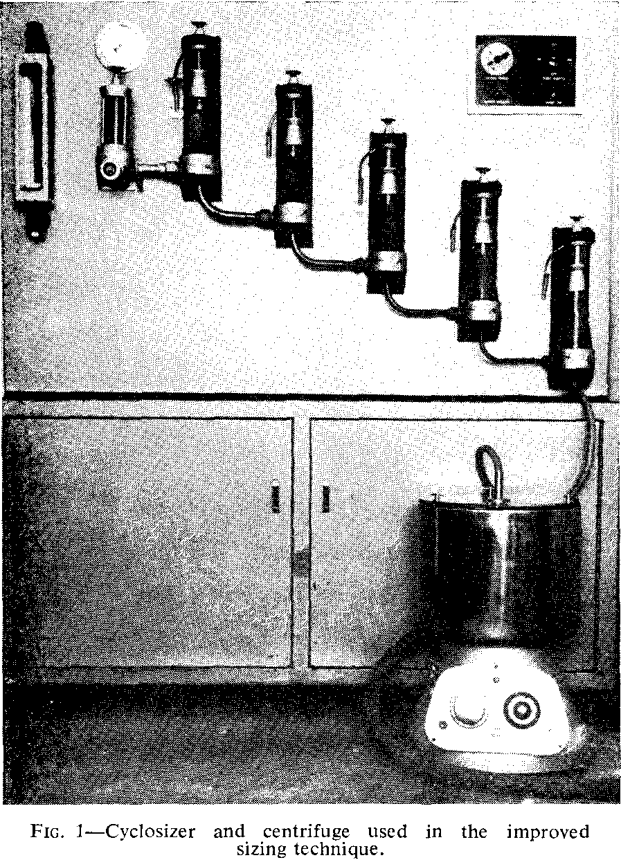
The design and operating characteristics of the hydraulic cyclone elutriator were described in detail by Kelsall and McAdam (1963), and the method of operation of the commercially available version, the Cyclosizer, is described in the manufacturer’s pamphlet (Anon). Complete details of the operating procedure are given in the relevant operating manual (Anon, 1964).
The cyclones which form the basis of the Cyclosizer (Fig. 1) under normal operating conditions produce typical cut sizes of 44, 33, 23, 15, and 10 µm for cyclones one to five respectively for material with a specific gravity of 2-7. At the end of the selected elutriation period each sized fraction is discharged and collected for subsequent assay or analysis but all material rejected by the fifth cyclone (e.g. minus 10 µm quartz) normally passes to waste.
When this material is needed for separate study, although its amount and average analyses can be calculated by difference, it may be necessary to collect more than 250 l. of very dilute suspension, flocculate the solids, allow to settle, and decant off the supernatant liquid.
This procedure is cumbersome and inconvenient and the simple technique to be described may offer some advantages. The temperature of the water fed to the Cyclosizer is maintained at a constant value for added reproducibility.
Procedure
The present overall treatment of the subsieve material (minus 37 µm) fed to the Cyclosizer incorporated several refinements compared with normal operation and these may be best illustrated by an actual example.
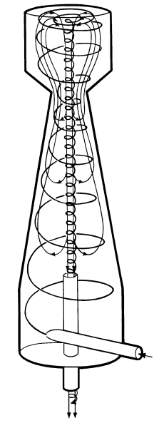
Material to be cyclosized (25 to 100 g depending on size distribution and specific gravity) is completely dispersed in water at 23 °C by vigorous stirring, using suitable dispersants if necessary, in a 2 1. beaker filled to a level marked 16 cm above the base. After a settlement period of 1 h, during which time a quartz sphere with a diameter of 6·5 µm would settle 14.5 cm, the upper 14.5 cm of suspension is removed using a special syphon (Fig. 2) designed to ensure minimum disturbance of the lower 1·5 cm of suspension.
The lower 1.5 cm is diluted with water at 23°C, to make up to the 16 cm level, the system redispersed and the 1 h decantation cycle repeated. The same procedure is repeated a further twice and the four decant suspensions combined for subsequent flocculation, settling, dewatering, drying, weighing, and assaying.
The coarse solids remaining in the beaker after the
container. The Cyclosizer is then operated as usual with water at 23°C but the water and material rejected by the fifth cyclone unit passes through a continuous centrifuge capable of retaining all solids with settling rates greater than that for a quartz sphere of 1·5 µm diameter.
Calculation, based on Stokes’ Law, shows that the feed to the Cyclosizer (after the four decantation steps) contains only 0.1 per cent of 2 µm equivalent quartz sphere material and 0.01 per cent of ultrafine material. Consequently practically all of the original material to be sized is recovered in seven fractions, i.e. in units 1 to 5 of the Cyclosizer, in the bowl of the centrifuge, and in the fines from the four decantation steps. In the absence of a centrifuge, particles leaving the Cyclosizer may be recovered after allowing the effluent to settle for a few hours, without the need for flocculation, since all very fine solids have been removed by decantation.
Equipment
Water temperature control
A water temperature of 23°C for decantation and cyclosizing was chosen as a typical summer cold water maximum. Cyclosizing at fixed water temperature ensures that cut points do not vary from one sizing run to the next. The pump box of the Cyclosizer is fitted with separate ball valves, and a manually operated valve fitted in the hot water supply line permits coarse temperature adjustment to approximately 21°C, measured in the region where hot and cold streams are mixed. A 2 kW immersion heater, fitted in the same region, is switched on and off by a mercury-wire contact thermometer, located at the exit of the pump box, or pump intake, and set to hold a temperature of 23 ± 0.25°C. If cooling (approximately 1 kW) is provided, the discharge from the centrifuge—virtually free of solids in this technique—may be recycled to the Cyclosizer making it practical to use liquids other than water as the sizing medium.
Centrifuge
The continuous centrifuge, shown in Fig. 1, is of the solid bowl type, capacity 3 L, 26 cm in diameter and 12 cm deep, rotating under load at approximately 3000 rev/min. The minimum separation diameter of the bowl, i.e. the diameter of the top opening where the liquid overflows, is 12.5 cm.
Decantation equipment
The apparatus used for settling and decantation is shown in Fig. 2. The syphon tube is fitted with a
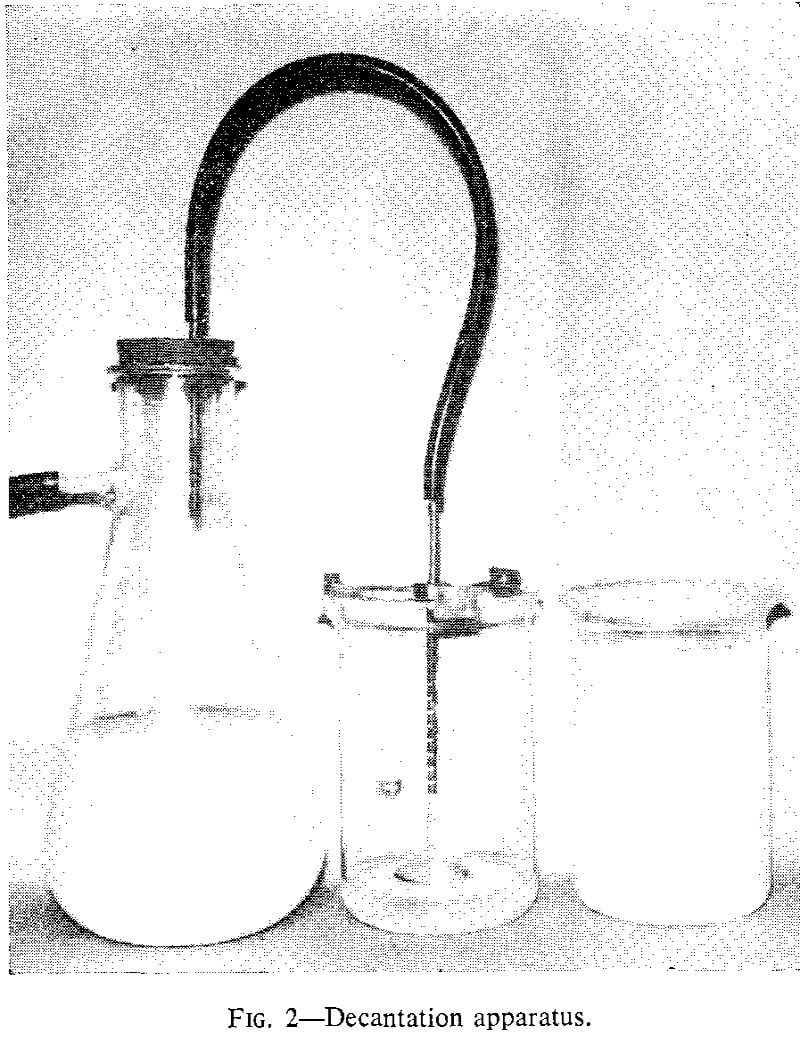
horizontal disc and the supernatant suspension is removed through three short vertical slits located at the base of the tube but above the disc to avoid disturbance of the settled solids.
General
Extrapolation to the finer sizes of the portion of the size distribution determined by the Cyclosizer, permits an estimate of the size corresponding to the weight fraction collected as decantation fines, i.e. of the effective decantation cut size. For a typical quartz size distribution this was found to be approximately 5·5 µm. Consequently the whole subsieve sizing operating produces seven separate fractions for assay. Thus for a typical quartz sample these are plus 44, minus 44 plus 33, minus 33 plus 23, minus 23 plus 15, minus 15 plus 10, minus 10 plus 5.5 and minus 5.5 µm respectively. Material balance is excellent.