
The flotation process is widely used for treating metallic and non-metallic ores and in addition, it is receiving an ever widening application in other industries. A greater tonnage of ore is treated by flotation than by any other single process. Practically all the metallic minerals are being recovered by the flotation process and the range of non-metallics successfully handled is steadily being enlarged. In recent years the art of flotation has been successfully applied in other than the mining industry, such as flotation of wheat, and other industrial applications. As flotation reagents are further developed, the application of flotation will be more widespread.
The “Sub-A” Flotation Machine has been applied to all types of flotation problems and these machines have continuously demonstrated their superiority. They have given very successful results through a wide range of problems, and their supremacy is fully proven by world-wide acceptance and application.
The feature of the “Sub-A” is the design. The “Sub-A” incorporates all of the basic principles and requirements of the flotation process and these, coupled with the special and exclusive wear features, make it the ideal flotation machine.
“Sub-A” Flotation Cells have been developed over the intervening years since 1927 until today there are over 35,000 cells in operation. Flotation cells are “standard equipment” for an ever widening range of metallurgical and industrial problems. They are being used in plants of all types and sizes and they are giving excellent results at minimum cost at tonnages of a few tons up to 35,000 tons per 24 hours.
To take care of the wide range of problems confronting the flotation process, the “Sub-A”s are built in a wide and flexible range of commercial sizes, from the No. 8 through the No. 12, No. 15, No. 18, No. 18 Special, No. 21, No. 21 Deep, No. 24 and the No. 30.
There is a particular size machine for every problem and tonnage, with each machine having incorporated into its design features to take care of any condition. This is the basis on which “Sub-A” Cells have been designed. Standard machines are as follows:
The construction of the “Sub-A” Standard Flotation Machine is with double welded steel tank, alloy iron cell side liners, rubber bonded to steel bottom liners, impellers and diffuser wearing plates of molded rubber or alloy iron, individual cell pulp level control, rubber protected shafts and rubber sand relief bushings. To the standard cells the supercharging principle can be quickly adapted as all recent cells are furnished with automatic air seal and air bonnet to which low pressure air is easily connected. Variations from the standard machine allow the pulp to bypass through convenient ports which can be opened or closed while the unit is operating. This feature makes the “Sub-A” either the exclusive positive circulation unit in an open type machine.
“Sub-A” in Corrosive Circuits
“Sub-A” Flotation Cells are built with special design for work in acid and corrosive circuits. The construction of this type machine is similar to the standard “Sub-A” except that the parts in contact with the pulp are of special materials and the tank itself is of wood construction. There is also a variation in design to take care of the special conditions usually associated with acid circuits and for convenience the acid-proof machines are built in 2-cell units.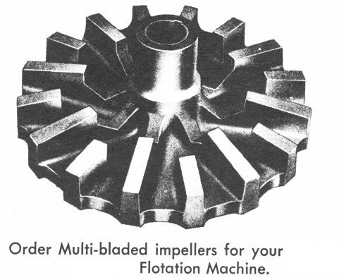
Principles of Operation of the “Sub-A”
The widespread success of the “Sub-A” Flotation Machine is attributed to the basic qualities of the design of this type flotation machine. Successful metallurgy results from the distinctive gravity flow feature, which assures positive circulation of all pulp fractions with reagents from cell to cell and hence results in high efficiency.
Pulp Flow and Circulation
The pulp flows by gravity into each cell through the feed pipe, from which it drops directly on top of the rotating impeller below the stationary hood. As the pulp cascades over the impeller blades it is thrown outward and upward from the impeller and diffuser wearing plate by the centrifugal action of the impeller. The pulp is kept in complete circulation by the impeller action and as the flotation reaction takes place, the pulp is passed from cell to cell. Pulp overflows to each succeeding cell over an adjustable weir gate in the partition. This gate gives accurate control of pulp level as the pulp passes through the machine. To take care of coarse oversize each cell has a rubber sand relief opening in the partition weir casting which feeds oversize direct to the impeller of the next cell without short circuiting. Circulation within each cell itself and return of middlings is by means of adjustable openings in the hood above each impeller, although for normal operation these are kept closed, except for middling return.
Circulation in “Sub-A” Flotation cells is highly efficient due to the distinctive gravity flow feature. This method of pulp circulation assures the positive circulation of all pulp fractions with resultant maximum treatment bf each and every particle. It is an established fact that the mechanical method of circulating material is the most positive and economical, particularly where the impeller is below the pulp. A flotation machine must not only be able to circulate coarse material (encountered in practically every mill circuit) but also must re-circulate and retreat the difficult middling products.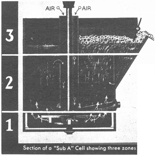
An alternate pulp flow is obtained from cell to cell by the side ports in the partitions. The ports are adjustable so that a portion of the pulp can pass from cell to cell through these ports and consequently bypass the impeller and weir overflow.
It is not essential to have each individual cell with separate weir gate control; however, for most installations this is recommended. An alternate arrangement is with gate control every two to four cells for pulp level control, and free pulp passage from cell to cell, by means of the ports, as well as cell to cell overflow. The arrangement is actually a “grouping” without sacrificing the positive circulation feature.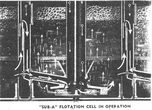
Aeration and Mixing
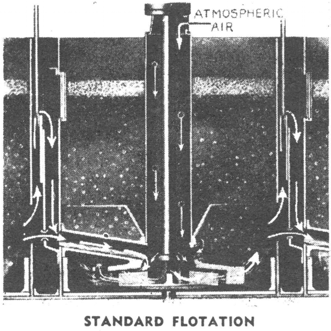
The passage of pulp through the cell and the action created in the impeller zone draws air down the stationary standpipe and from the partition along the feed pipe. This positive suction of air gives the ideal condition for average flotation and the action in the impeller zone thoroughly mixes the air with the pulp and reagents. As this action proceeds, a thoroughly aerated live pulp is produced and furthermore, as this mixture is “ground” together by the impeller action, the pulp is intimately diffused with exceedingly small air bubbles which support the largest number of mineral particles.
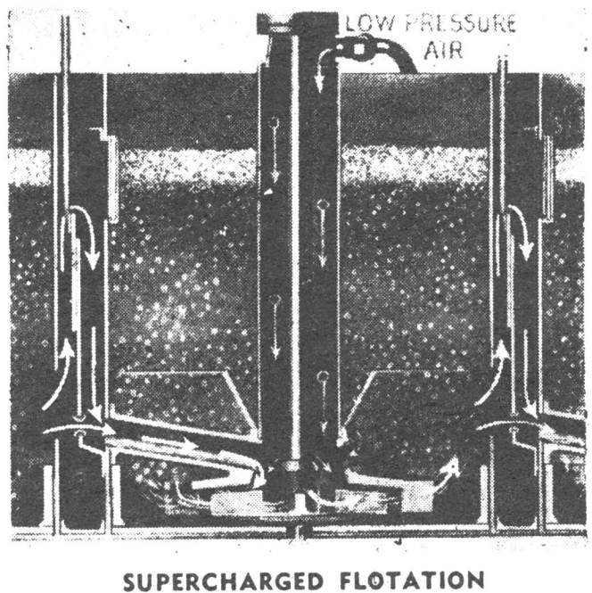
For particular problems the aeration in the “Sub-A” can be augmented by the application of “Supercharging,” whereby fully controlled air under low pressure is diffused into the pulp. This feature is accomplished by the introduction of air from a blower or turbo-compressor through the standpipe connection into the aerating zone where it is pre-mixed with the pulp by the impeller action. This supercharging of the pulp creates a highly aerated condition which is maintained by the automatic seal in the cell partition. Supercharging is of particular advantage for low ratio of concentration and slow-floating ores.
It is recommended for use with all No. 30 installations. Supercharging has been responsible for:
- better metallurgy;
- lower power consumption;
- increased capacity;
- reduced reagent consumption;
- improved operating conditions.
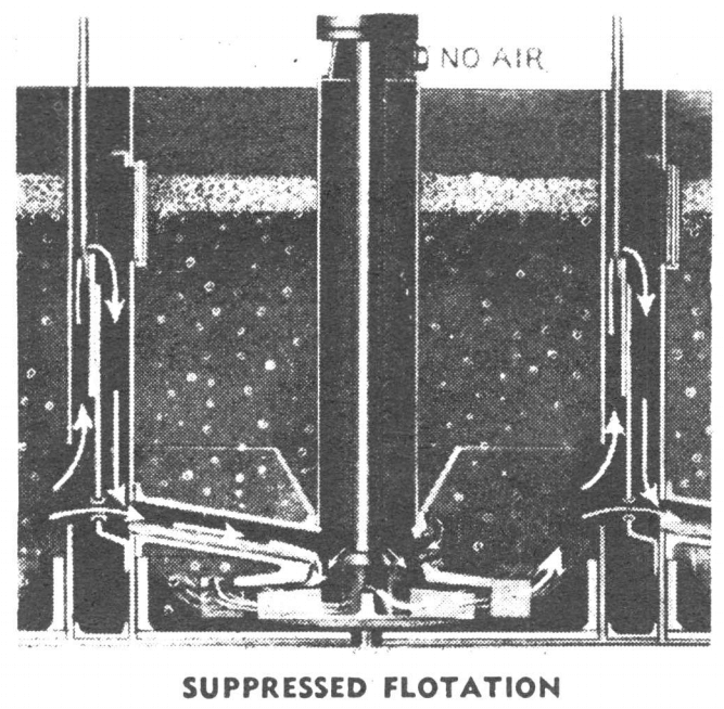
Throttling of air in the “Sub-A” Flotation’ Machine is of benefit when suppressed flotation is required. This is accomplished by cutting off or decreasing the size of air inlet on the standpipe. Suppressed flotation finds its chief use in grain flotation, certain non-metallics and occasionally in cleaner or recleaner operations.
The aeration and mixing of the pulp with reagents all takes place in the lower zone of the cell. This thorough mixing, which is below the stationary hood, is to a considerable degree responsible for the metallurgical efficiency of the cell.
Supercharging “Sub-A” Flotation Cells by increasing the sub-aeration is obtained with a small volume of air at low pressure. The air bonnet and automatic air seal are integral parts of all standard “Sub-A” Cells; hence, to increase the aeration all that is required is a connection from the air bonnet to a source of air supply.
Separation
The aerated pulp, after leaving the mixing zone, passes upward by displacement to the central section of the cell. This is a zone of quiet and is free from cross currents and agitation. In this zone, the mineral-laden air bubbles separate from the worthless gangue and pass upward to the froth column without dropping their load, due to the quiescent condition. The gangue material follows the pulp flow and is rejected at the discharge end of the machine.
It is in the separation zone that effective aeration is essential and this is assured in the “Sub-A” as the air is broken up into minute bubbles. These finely diffused bubbles are essential for carrying a maximum load of mineral.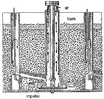
Concentration
The mineral-laden bubbles move from the separation zone to the pulp level and are carried forward to the overflow lip by the crowding action of succeeding bubbles. To facilitate the quick removal of mineral-laden froth, “Sub-A” Flotation Machines are equipped with froth paddles. Froth removal can be further facilitated by the use of crowding panels which create a positive movement of froth to the overflow.
Concentrates produced by “Sub-A”s are noted for their distinctive high grade and selfective-ness. The spitzkasten built into “Sub-A” cells is partially responsible as it allows a quiescent zone just before froth removal in order that middling fractions may fall back into the pulp flow. Machines are built with single overflow as standard, but double overflow can be supplied.
Operating Advantages with “Sub-A”:
- Coarse material handled
- No choke-ups or lost time
- Middling return without pumps
- Positive cell control
These are several of the distinctive advantages obtained with the use of “Sub-A” Flotation Cells which are found in no other flotation machine. The combination of these several advantages is necessary to obtain successful flotation results.
Coarse Material Handled
Positive circulation of all pulp fractions from cell to cell is assured by the distinctive gravity flow principle of the “Sub-A”. No short circuiting can occur through the machine; hence, every particle is subject to positive treatment. In instances where successful metallurgy demands the handling of a dense pulp containing an unusually large percentage of coarse material, the sand relief opening aids in the machine operation. This opening removes from the lower part of the cell the coarse fractions and passes them through the feed pipe to the impeller of each succeeding cell. The sand relief openings assure the passage of slow floating coarse mineral to each impeller and therefore it is subject to the intensive mixing, aeration and optimum flotation condition of each successive cell. The finer pulp fraction passes over the weir or through the intermediate ports. The passage of the coarse fractions through each impeller eliminates short circuiting and thus, both fine and coarse mineral are subject to positive flotation.
No Choke Ups or Lost Time
A “Sub-A” cell will not choke up, even when material as coarse as one quarter inch is circulated. Choking cannot occur as the feed to each cell is to the top of the impeller. After a shutdown, it is not necessary to drain the machine as the stationary hood with diffuser wearing plate protects the impeller and.feed pipe from sanding-up. Even though the flotation feed is finely ground, coarse material occasionally gets into the circuit and if the flotation machine does not have the gravity flow feature, sanding and choke-ups will occur. This gravity flow principle of pulp circulation has made possible the widespread phenomenal success of a flotation cell between the ball mill and classifier. The recovery of mineral, as coarse and as soon as possible, in a high grade concentrate is now considered a requisite to a maximum metallurgical efficiency and hence “Sub-A” operators value its “24-hour per day service” and freedom from shutdowns.
Middling Returns Without Pumps
Middling products from “Sub-A”s can be returned by gravity from any cell to any other cell in the average flotation circuit. The flexibility is possible without the aid of pumps or elevators. The middling pulp flows to the required cell and by means of a return feed pipe, falls directly on top of the impeller, assuring positive treatment and are-ation of the middling product without impairing the action of the cell. This feature, exclusive with “Sub-A”, is of particular advantage in circuits where several cleaning steps are required to bring middling products to final grade.
The initial feed can also enter into the front or back of any cell through the return feed pipe.
Positive Cell Control
“Sub-A” cells are under full control with normal operating conditions. The pulp level is maintained at the desired place with adjustable weirs. Aeration is controlled with flexible methods of air addition which allow variable aeration for different conditions. Any overloads or surges of coarse material from the grinding circuit are effectively taken care of with the sand relief openings, ports or quickly adjustable weirs. With these control features the operator has every opportunity to maintain his circuit in balance. Pulp fluctuations can be minimized and absorbed due to the control features.
Metallurgical Advantages of a “Sub-A” Flotation Cell
Selectivity
“Sub-A” Flotation Equipment is metallurgically unsurpassed for the production of concentrates most suitable for subsequent thickening, filtering and smelting.
The selectivity of “Sub-A” through all mesh sizes is one of the outstanding features of this flotation machine. Selectivity in Cells is not by chance, but results from the basic principle in design. The distinct gravity flow feature, coupled with the individual cell construction, controlled individually or in groups, and positive circulation through the machine, is to a large degree responsible for the recovery of coarse products by flotation. The advantage of positive circulation becomes obviously important with coarser grinds. A homogeneous and thoroughly mixed pulp is circulated at all times in each cell and there is no tendency towards classification and segregation. Thorough mixing and aeration of all pulp fractions by positive circulation is the only means of obtaining selective flotation and metallurgical efficiency through all mesh sizes. The absence of pulp stratification prevents slime recovery from surface pulp or “drift” of heavy granular fractions through the machine.
Selective flotation with “Sub-A” results in several major features, such as:
- Coarser grind possible
- High Ratio of Concentration
- Coarse products more acceptable for dewatering and smelting.
- Low volume of middling for re-circulation
- Selectivity allows machine to do mechanically that which is frequently attempted with reagents.
Recovery:
Recovery in flotation is of prime importance. In studying recoveries it is essential also to investigate thoroughly the intermediate products produced. It is a simple matter to make a high recovery or a low tailing if no thought is given to the nature of the concentrate produced or circulating load. “Sub-A” Flotation Cells will produce a high recovery, coupled with a high grade concentrate, low volume of middling, and a final concentrate most acceptable for subsequent treatment. The overall efficiency of this flotation machine will assure an equitable balance between recovery and nature of products produced.
Balanced Products Analysis
“Sub-A” Flotation Cells have demonstrated that they alone produce products most acceptable for economic efficiency. In competitive tests where all phases of the operation are studied in thorough detail, it has been proven time and again that “Sub-A”s show metallurgical advantages which contribute to the highest overall efficiency of an entire mining operation. “Sub-A” cells are:
- More selective through all mesh sizes.
- Produce a coarser concentrate.
- Produce a concentrate more acceptable to subsequent treatment.
- Produce equal or higher recovery in conjunction with a higher grade concentrate and higher ratio of concentration.
A comparison of product assays does not give true and complete information- with respect to the performance of a flotation machine. Product assays for two flotation machines operating in parallel could quite conceivably be identical, yet the physical characteristics of the products recovered and discarded would be entirely dissimilar. Wide differences which would be obvious in detailed investigation might not be indicated by a cursory examination. A detailed study of flotation concentrates shows that “Sub-A”s recover the coarser more granular sulphides which parallel machines lose in the tailing. The higher recovery of coarse concentrate has been the story in every instance where “Sub-A” cells have been on a comparative basis. The use of “Sub-A” cells is responsible for the trend in concentration by flotation of coarse granular concentrates with minimum slimes. Higher recoveries have been possible in many instances by changes in grinding and removal of coarse primary concentrates. Recovery at a coarser grind means a decreased amount of slime mineral in the pulp. Absence of slime in concentrates is reflected in the analysis of the insoluble fraction. “Sub-A” cells always show a lower percentage of slime in concentrate due to selectivity and this means minimum refractories in subsequent treatment.
Variations in tailing analysis show the same differences as those portrayed for concentrates. A detailed study will show where the “Sub-A” rejects slime to waste.
Screen analysis of products recovered and rejected clearly demonstrate the absence of sanding and segregation in “Sub-A” cells and the patented positive circulation principle assures balanced products.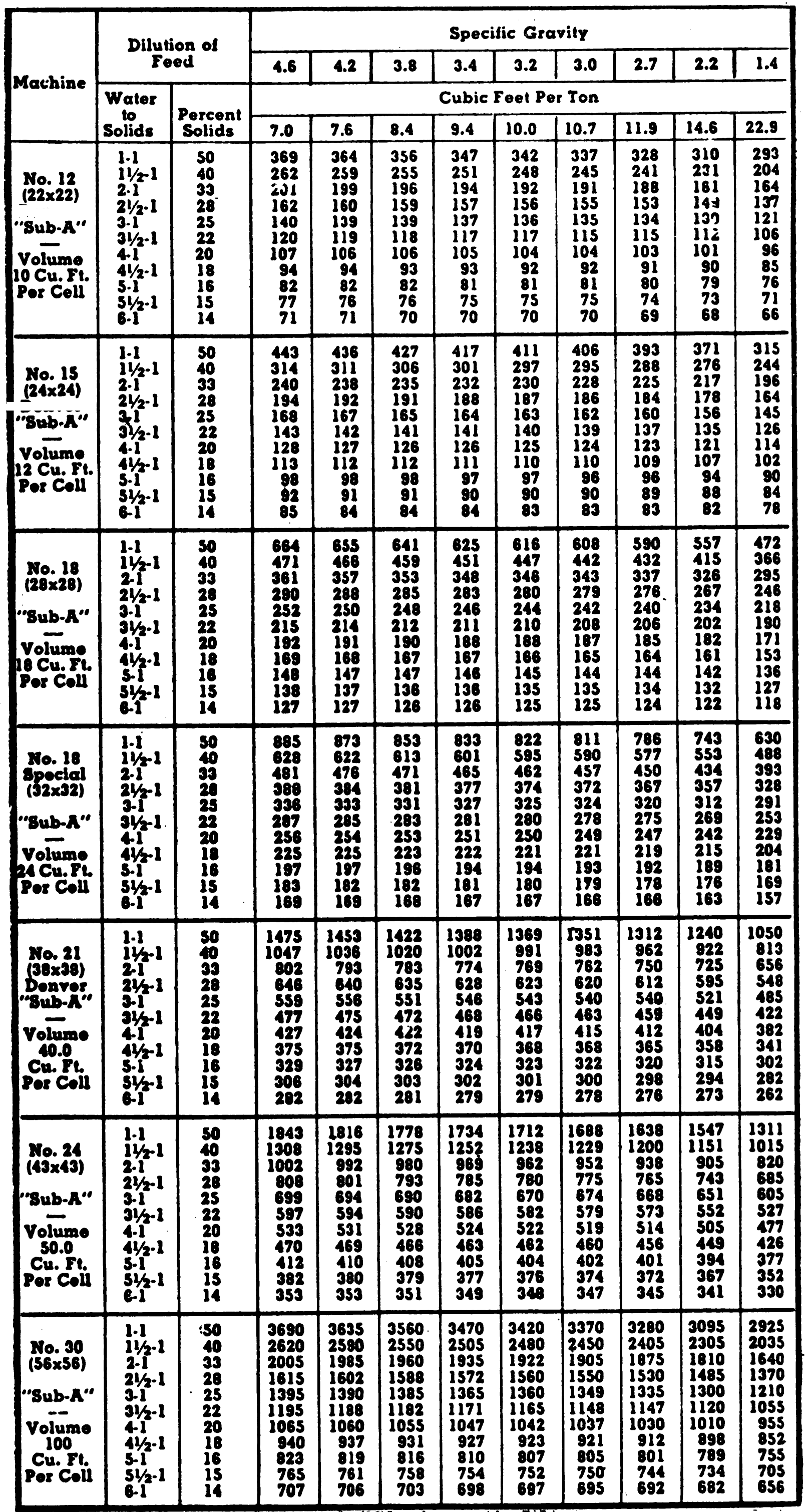
Capacities
The capacity of a flotation cell, treating any ore, depends upon facts and conditions which can best be determined by experience and test work. The pulp density and flotation contact period required materially affect the capacity of a flotation machine. With these factors known from previous work or test results, the size machine can be determined. Three conditions are factors in determining the proper size machine and number of cells.
-
Capacity:
Flotation contact time required for the ore is one of the determining factors in calculating flotation cell capacity. If an ore is slow floating and requires twelve minute treatment time, and another ore is fast floating and requires but six minute treatment, it is evident that a machine of only half the capacity is necessary in the last instance. Pulp density and specific gravity of dry solids control the cubic feet of pulp handled by the flotation machine, so are determining factors in calculating the flotation contact period. The “Sub-A” capacity recommendations are conservative figures which are based on years of actual field operation, treating many kinds of material.
-
Volume:
The volume of the flotation cell must be known, as the volume in the flotation machine determines the time available for flotation of the values to take place. Therefore, the capacity of any flotation machine is dependent on the volume. All flotation cells having the same volume will have approximately the same capacity, with allowance made for horsepower, the efficiency of the impeller and aeration. As the flotation contact period is very important in any flotation machine, the actual cubical content of any machine should be carefully checked as well as accurate determinations on average pulp specifications.
-
Results:
Metallurgical results required from the flotation machine will have considerable bearing on the installed capacity. Several stages of cleaning may be required to give a high grade concentrate and this can be accomplished by the “Sub-A”, usually in one machine without resort to pumps for middling return. Results with cells of equal volume will not necessarily be equal because they may not be equally efficient. It may be easy enough to pass pulp through a flotation machine but to have a machine give a high-grade concentrate, to retreat middlings, and to give a low tailing, is an advantage obtained by use of “Sub-A”s.
The maximum results are obtained by the “Sub-A” at minimum cost, as the “Sub-A” recovers the mineral at the critical size in a machine protected fully against wear.
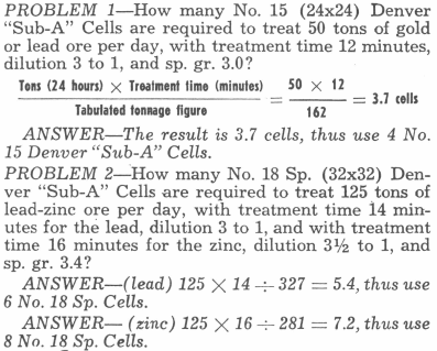
Under the table, problems are given to illustrate the methods of calculating the number of cells required. In order to secure the maximum positive treatment of the mineral, and to produce a high grade concentrate, it is best to have the necessary total volume divided into aft least four cells and preferably six cells, each a separate cell, so that they may be used for roughing, cleaning, or recleaning purposes.
To determine the number of “Sub-A” cells required—multiply* the proposed tonnage per day (24 hours) by the time (number of minutes necessary to float the mineral) then divide this product by the proper figure given in the table. This figure is secured by taking the size machine under consideration (find the horizontal line giving the dilution of mill pulp and the vertical line giving the specific gravity of your ore); the figure will be at the point of intersection.
Construction of “Sub-A” Flotation Cells
Continuous “24-hour per day service” depends upon the mechanical design and construction of a flotation machine. There is no unit so rugged, nor so well built to meet the demands of the process, as the “Sub-A” Flotation Machine. The ruggedness of each cell is necessary to give long life and to meet the requirements of the process. Numerous competitive tests all over the world have conclusively proved the real worth of these cells to many mining operators who demand “Maximum results at the lowest cost.”
The location of the feed pipe and the stationary hood over the rotating impeller account for the simplicity of the “Sub-A” cell construction. These parts eliminate swirling around the shaft and top of the impeller, reduce power load, and improve metallurgical results.
Improvements in construction of “Sub-A” cells during the last ten years have been gradually made as a result of plant scale testing and through suggestions from the mining fraternity. Today the “Sub-A” is mechanically unexcelled with rugged construction, pressure cured wearing parts, heavy duty, dependable drives. The abrasive cell zone is protected with rubber bottom liners and hard iron or Decolloy side liners. The heavy duty shafts are also rubber protected so the entire abrasive zone is sheathed for protection against wear.
The “Sub-A”, with its distinctive advantages, is moderately priced, due to standardization and quantity production. There is a definite mechanical or metallurgical reason behind the construction of every part of the “Sub-A” as explained in the following specifications.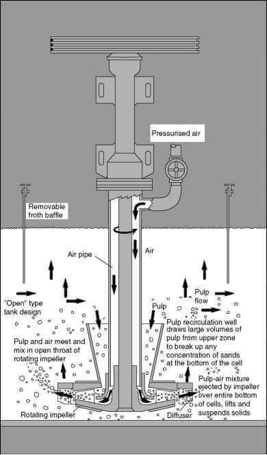
All Steel Construction
The tank for the “Sub-A” Flotation Machine is made of heavy steel . . . joints are electric welded both inside and out. Partition plates are furnished with gaskets and arranged for bolting to partition channels so that if necessary all of the plates can be changed at any time in the field to provide either a right or left hand machine. Right hand machine is standard and will be furnished unless otherwise noted.
“Sub-A” Flotation Machines are also available in wood tank construction especially suitable for corrosive circuits. These machines can be supplied with modifications so that they are ideal for use in special applications.
All cells are placed at a common floor level and due to the gravity flow principle of “Sub-A” Flotation Machines almost any number of cells can be used in any circuit at one elevation without the necessity of pumps or elevators to handle the fl’ow from one machine to the next. Operation and supervision is thus simplified.
For export shipments all of the items for the flotation machine are packed, braced, and blocked inside of the steel tank so that minimum volume is required. Safe delivery of parts without damage is thus assured.
Bearings and Housing
The shaft and bearings of the “Sub-A” are supported in an enclosed ball bearing housing designed to properly carry and maintain the rotating impeller. Both the upper and lower heavy duty, oversized, anti-friction bearings are seated in this housing, insuring perfect alignment and protection against dirt.
Bearings have grease seals to prevent grease or oil getting into the cells; lubrication is only*needed about once in six months. Many thousands of these standard bearings are in daily use on “Sub-A” cells, giving continuous service and low horsepower.
Stationary Hood
The hood, which is located near the bottom of the cell, is an important part of the assembly as it serves a number of purposes. The vanes-on this hood prevent swirling of the pulp in the cell, producing a quiet action in the central or separation zone. The hood also supports the stationary standpipe and the hood wearing plate. Aeration of the pulp takes place in the impeller zone just below the stationary hood. The wearing plate is bolted to the bottom of the hood and prevents the impeller from being buried by pulp when the machine is shut down.
Long Life Wearing Parts
The maintenance cost of wearing parts in many large plants has been reduced to a minimum due to the use of molded rubber parts, which are available for all sizes of “Sub-A” Flotation Machines.
Data from large operations have shown that the life of rubber parts is from six to fifteen times longer than the life of hard iron wearing parts. The slightly greater cost of these parts is therefore more than offset by the longer life. The advantages gained not only in lower maintenance but also in reduction in horsepower (because of the lower coefficient of friction when using molded rubber impellers) make them most economical. Both receded disk and conical disk wearing parts are also available in special hard alloy iron.
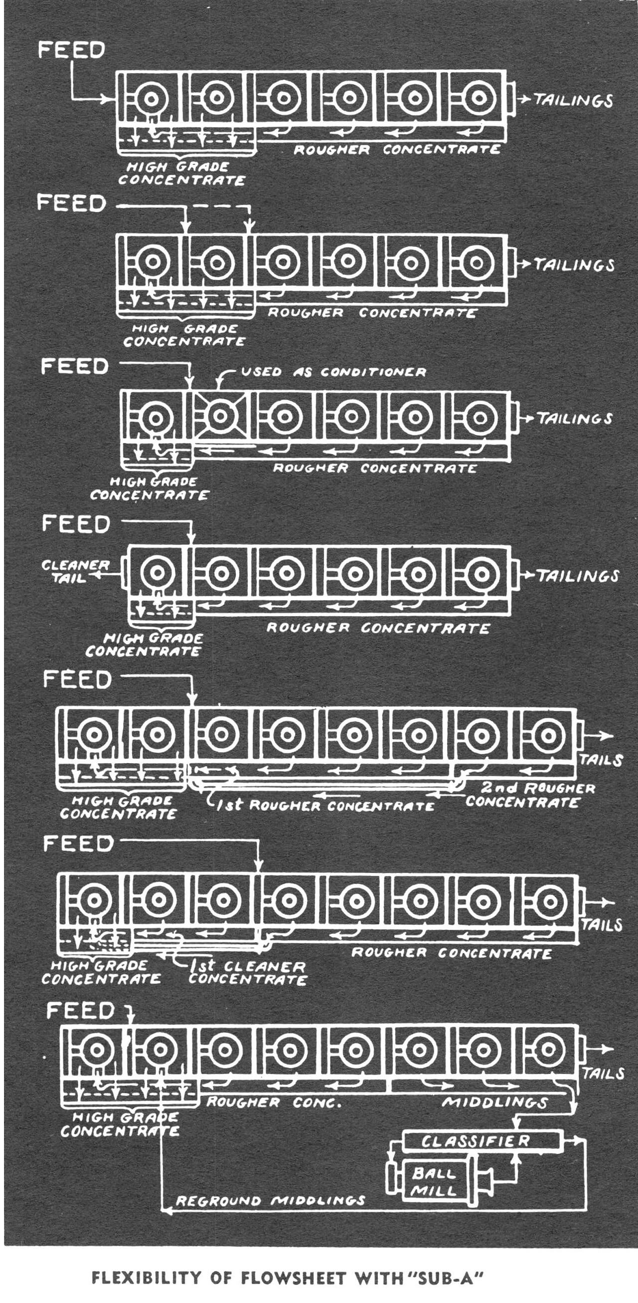
Circuit Flowsheet Flexibility
Source: This article is a reproduction of an excerpt of “In the Public Domain” documents held in 911Metallurgy Corp’s private library.