
The Gold Jig or Mineral Jigs are important of all types of alluvial gold concentrating device among all gravity separation methods; they are also the most complex and the practice of jigging in mineral processing is often viewed as an art rather than a science. Gold jigging has been referred to as being probably the most complex gravity operation because of its continuously varying hydrodynamics. The mineral bed is repeatedly moved up by the water, expands, and then re-settles, the resettlement occurring with the water flowing down at a lower rate (because of the addition of hutch water) than that which occurred on the upstroke. It follows that the waveform itself must be a significant parameter. The manner in which the bed expands is also important because of its marked effect on the particle dynamics. A number of experimental studies are reported in the literature but too often they fail to contribute to the understanding of gold jigging. This conflicting information appears to arise because many studies were carried out on a narrow set of ideal conditions that resulted in behaviour quite unlike that associated with practical gold jigs.
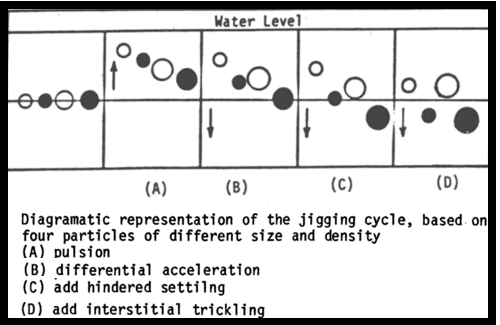
Theories of jigging also tend to describe the mechanism of separation in pulsating water in general terms but without any complete understanding of the processes involved. The most favoured explanation is that stratification occurs in the jig bed as a result of a combination of three mechanisms:
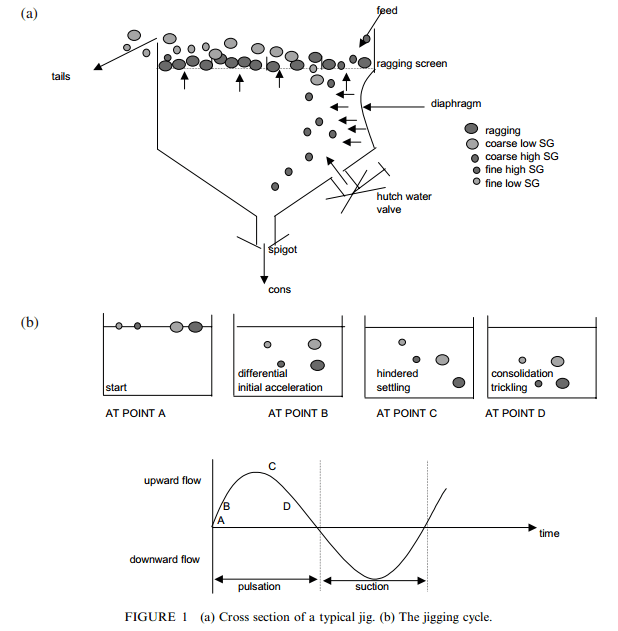
- The bed is lifted “en masse” in the upward flow but differential acceleration occurs at the end of the pulse when the water reverses its flow to a downward direction.
- The particles are subjected to hindered-settling conditions during most of the downward flow.
- Interstitial trickling takes place during the final part of the downward flow before the pulse changes direction for the next cycle.
The above mechanisms assume initial upward flow without stratification; the materials being lifted en masse. This is probably not so, and since there is no direct experimental confirmation of the actual behaviour of the particles concerned, a complete understanding of the separation process still remains to be achieved. Similarly, while repeated dilation and compaction of the bed takes place as a result of water pulsation, the separation mechanism has not yet been demonstrated theoretically in quantitative terms. Suggestions by workers in coal and other fields that interstitial trickling mechanisms should be looked at more closely. Investigations by researchers outside the field of mineral processing have indicated that the ‘interstitial trickling’ mechanism is likely to be a strongly geometrically dependent effect; large particles being displaced upwards by small particles when all particles are of the same density.
It is also likely that the deterministic approach implicit in the existing mechanisms, which effectively consider the motion of a single particle in isolation, will have to be abandoned in favour of a stochastic or probabilistic approach.
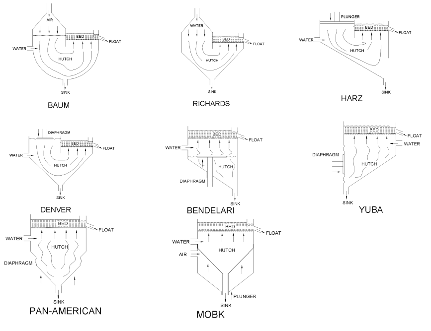
The practical importance of jigging is that stratification occurs with the denser minerals at the bottom of the bed and the lighter minerals at the top. Two main jig types, rectangular and circular, are linked through a trapezoidal jig form.
We can compare the flow pattern over a rectangular jig with the pattern of flow over a trapezoidal jig section of a circular jig.

Rectangular gold jigs are made of either a single 1 jig-cell as stand-alone, or a series of cells organized in modules of two (duplex jig), three (triplex) or four cells (quadruplex). In a multiple-cell jig design/setup, the rejected tailings from the front cell passes thru as feed to the following second cell compartment; tailing from the second cell vessel is feed to the 3rd-third cell and on down the bank. Ordinarily, roughing duty is done using three- or four-cell modules. The double or two-cell arrangement that is commonly called the duplex is ordinarily confined to secondary circuits and cleaning systems. Over mineral processing history, jig designs have not changed much and in today’s practice, rectangular jigs are mostly limited to roughing tasks in flowsheets where low starter initial cost is a important, or where the gold is preponderantly in grains > 200 um and therefore easy to recover.
Fans of the rectangular jig design, will admit and understand all jigs have the common disadvantage of lower recovery for gold finer than approximately 200 um. The lower finer gold recovery jigs have is principally caused by these factors:
- the increment in cross-flow velocity over the jig bed as a result of the adding of hutch water to each cell compartment in series,
- the fundamental nature of the jig motion and action.
The alliance of an uninterrupted hutch water provision and water displaced by the onward stroke of the diaphragm stimulates a speedy upwardly flow of water through the ragging and mineral bed, after which a lazy descending flow on the opposition stroke. The whole jig bed (ragging plus mineral bed) is expanded on the forward stroke and consolidates on the reverse stroke. The inclination is for fine and flaky gold to hold in suspension and report (be rejected) to tailings.
A circular gold jig system gives a single unit the possibility for a large throughput in common feed inlet. This has for outcome a feed system without splitters and a better pattern of cross-flow with less negative side effects. The improved control that results of the hutch water provides increased gold recovery of fine gold at even at high feed volumes. The factor restricting the jig is its ability to recover a maximum quantity of recoverable gold and gold rich minerals to the concentrate, and yield a tailing that can be rejected without the need of more treatment.
Circular jig types are typically constructed from 12 modules (30° segments of circles) which together complete a full circle. Because flow takes place radially over a steadily increasing jig bed area the flow velocity decreases outwardly thus providing improved conditions for fine particle settling. Mechanical skimmers, which even out the flow over dead spots developed in non-pulsating sectors, attack the problem of dead spots through a combination of improved distribution around the central feed point, closer control of backwater, and the use of non-clogging jig screens. Perforated retarding plates and a longer feed intake length have been found to provide better flow deceleration at the entrance to the jig bed than the early form of distribution through a spigot under pressure.
The modern circular jig is manufactured with diameters up to 7.6 m and capacities up to 250 m/hr. Their main disadvantage is batch-type operation, which lowers their overall efficiency and reduces overall production time. See a circular hand operated jig.
Regardless of type, the jig is a simple gravity separation metallurgy machine as it is essentially an open tank filled with water with a slightly inclined screen at the top and provided with a spigot on the underside for drawing off the concentrate. Screen compartments comprise shallow flat trays having perforated bottoms loaded with coarse heavy particles such as haematite pebbles, steel punchings or steel balls to a depth of 25–50 mm. This material, known as ‘ragging’, is coarser than the screen apertures and with density intermediate between that of the minerals to be separated. Its purpose is to provide a non-cohesive layer of pebbles above which the resulting dilation and compaction of the bed will cause the minerals to stratify with the densest at the bottom of the bed and the least dense at the top of the bed. A hutch, fitted with a concentrate discharge valve or spigot, hutch water inlet valves and a diaphragm of moulded, reinforced rubber is located below the perforated screen plate. The diaphragm is activated mechanically through an external eccentric drive mechanism or through a mechanical/hydraulic drive.
Gold Rush
Primary jig feed normally comprises de-slimed minus 10 mm screen undersize fraction, although the sizings may be coarser than 25 mm in exceptional circumstances (e.g., if the gold is very nuggetty). Secondary and tertiary jig feeds are classified according to the size of the screen plate apertures. Pulp density may range from about 10–30% solids by weight, but is optimal around 25%. Jigs operate most efficiently when deslimed feed is introduced evenly and at a controlled pulp density across the full width of the live section. The hutch water should not contain more than 1.4% solids. Too little water results in uneven solids distribution and a tendency for the development of ‘dead’ spots in the jig bed. Slime affects slurry rheology through changes in apparent viscosity and density and is detrimental to the recovery of fines. Allowable slime tolerances are probably much lower than 5%.
The term ‘bed’ in jigging practice refers to solids on top of the jig screen. It is formed during the first stage of separation when the heavies in the jig compartment work their way down into the ragging. The light materials overflow the hutch to be either further processed or discarded. Particles of gold larger than the screen plate apertures accumulate in the ragging and are recovered when the screen basket is cleaned. The smaller, heavy particles are further concentrated as they work their way down through the screen plate and into the hutch.
The components of the jig’s bed start with a bottom bed of ragging AKA steel shots, that is normally introduced artificially, or in some cases is built up naturally by heavy mineral that were present in the ore feed to the jig. Ragging variables affecting the separation character of the jig bed are density and size. The ragging should have a density between the gold and the jig’s tailings and sized so as to pulse and produce open spaces for the gold to move thru it. Ragging dimensions can range from 5 mm to 20 mm and need not be so small and cause blinding of screen apertures or too large for its functions negatively affected or prevented. As a general rule: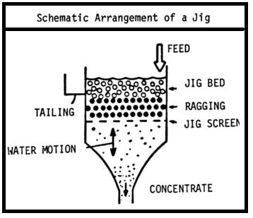
• The thicker the layer of ragging the less concentrate will pass through and gold losses will be higher.
• Very dense ragging reduces the amount of concentrate recovered because excessive velocity of up-flow is needed to dilate the bed; this throws some of the heavies up with the lights making it easier for them to be lost.
• A larger ragging size will increase the amount of concentrate but this will be of lower grade.
A disadvantage of all non-continuous jigging gravity processes is that gold recovery drop as the ragging becomes increasingly negatively modified by the heavy rock-forming minerals like pyroxene, tourmaline, magnetite and pyrite). The jig bed becomes a mixture of mainly lighter heavy minerals and heavy precious minerals (including gold) and ragging. The grade of the gold-bearing concentrate going through the hutch increases and sooner or later reaches a point of practical balance at where % recovery and the grade of the gold concentrate are optimum.
Simultaneously, the least heavy (lighter) of the heavy mineralized particles (yea really) carry-on in accumulating in the ragging. The production of gold concentrate decreases as less space remains for movement of the heavies and more small gold ore particles. Upward pulsations may be augmented to move the heavier jig bed but the operation will in the end turn uneconomic, as recovery drops and more gold is lost to the tailing. At this point, you need to replace the tray with a newly loaded tray of clean ragging. If not lost in the process, the contaminated jig bed steel shots (ragging) is cleaned, its gold recovered using a pan or amalgamation. In a multi-stage/duplex rectangular jig the first compartment will demand a higher frequency of cleaning.
The sand bed is a layer of coarse and unclassified sand formed by the feed less the material passing in the ragging and the top flow. Freedom of movement of the mineral particles in this layer is essential for good separation during dilation and fluidisation of the bed. Optimal dilation of the bed is given by a fast, short upward stroke to lift all of the mineral particles and a long, slow return slope allowing them to settle. Constraints to good separation are caused by compaction of the sand bed due to excessive spigot discharge or lowering of the tailing discharge height and
loosening of the sand bed as the result of excessive inflow carries with it the risk of lifting fine gold particles into the overflow fraction.
The jig screen/sieve is the final point of separation between light and heavy particles smaller than screen aperture size. Aperture size, which typically ranges between 4.5 mm and 6.4 mm, is so arranged as to provide open spaces over about 20% of the total screen area. In trashy flow conditions, blinding causes channeling of the flow and uneven dilation across the bed; losses mount rapidly and production time is lost in frequent shut down periods for changeover and maintenance. To minimise these problems the modern jig screen is fabricated as a rigid punched- hole screen backed by a soft rubber punched-hole screen. More recently, a full rubber screen with a two-layered was produced with hard rubber backing and soft rubber top. The rubber screen has holes smaller than the concentric holes of the stainless steel screens giving each hole a moveable rubber rim. The mineral bed thickness and slope of the cross-flow are regulated by upward and downward adjustments of the tailing weir. A shallow weir increases the top water flow rate, which should generally be less than 0.5 m/s. The average sand flow velocity across the jig is considered to be optimal at 0.076 m/s.
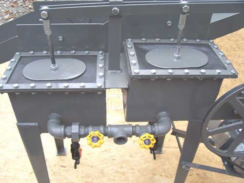
Spigot discharge: Collection and discharge of concentrates within the jig hutch are accompanied by the inflow of water to compensate for water passing out with the concentrates. Discharge of solids and water from the spigot alters the balance between upflow and downflow. Jig separating characteristics are held steady by increasing the intake of hutch water proportionally to the amount of water discharged. The balance between upflow and downflow is maintained by increasing the intake of hutch water to compensate for the lack of balance caused by removal of solids and water from the spigot. The concentrate discharge can be controlled in a number of different ways. A simple method is the use of a rubber plug with a cone-shaped orifice, generally tapering from around 12 mm to 10 mm at the outlet. Gooseneck arrangements with a simple wooden squeeze clamp are reasonably satisfactory for small operations. ‘Non-chokeable’ spigot cyclones use less water but the flow increases with wear.
Pulsation: Achieving a reasonable balance between stroke and frequency depends upon the nature of the particles, particularly the size-density relationships. The stroke length is largely determined by the upper size limit of the solids and since this is at its maximum level in the primary jigging circuit, the primary jigs will normally operate with longer strokes than in the secondary and tertiary circuits. Pulse frequency is adjusted inversely with the length of the stroke. Standard stroke lengths vary over the full range of Yuba Jigs from 3.175 mm up to 76.2 mm advancing in increments
of 3.175 mm. Frequencies range generally from 350 to 125 strokes/minute.
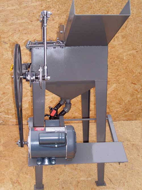
Jig Drive: The diaphragm is activated by drive systems ranging in type from simple eccentric drives to semi-hydraulic and hydraulic drives. The action of the diaphragm provides a continuous sequence of rapid pulses during which the direction of flow is reversed sharply, several times each second. Modern practice is moving away from the conventional harmonic waveform jigging cycle to an asymmetrical fast upstroke–slow downstroke pattern. You can illustrates the jigging characteristics using a special shaped cam drive system to produce a fast upstroke-slow downstroke (saw-tooth) pattern. The range of fine gold recovery usually extends from about 60% of 150 μm gold for conventional rectangular jigs to about 85% of 150 μm gold for jigs with mechanical and hydraulic and fully hydraulic drive systems, which include asymmetrical movement of the diaphragm. Current research is aimed at developing methods of monitoring bed dilation to achieve automatic control of the jigging process; this has not yet been achieved.
Jigs are the best all-round units for coarse gold separation in roughing service but good recovery is limited to gold grains larger than 100–150 μm in well-classified feed. In the science of mineral processing technique, beneficiation processes (with and without gravity separation) have been extended by investigative research to include compound water cyclones and rotating bowl separators in which centrifugal forces are used to enhance gravity differences, and combined gravity/froth flotation techniques and centrifugal jig separation. An important aim has been to accurately predict the stratification of typically equant heavy mineral particles in shear flow and under the pulsatory conditions of the jig bed.
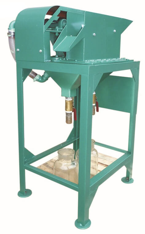
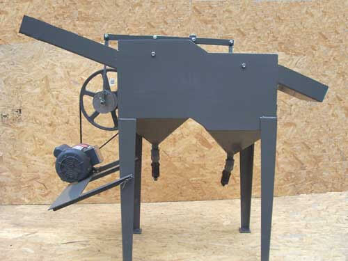
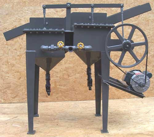
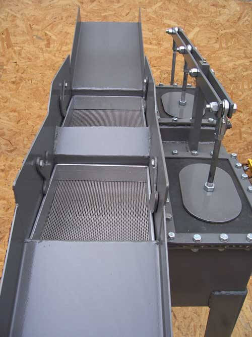
EXAMPLE OF 10″ X 12″ – 12″ X 16″ – 18″ X 22″ – 24″ X 28″ 42″ X 42″ Duplex Models
Jig Bedding Balls in various sizes.
All models are custom built for high volume input and efficient hutch recovery. The duplex feature (2 cells per jig unit) offers a second concentrating cell to further recover any heavy minerals that may have passed the initial cell. Design characteristics are built into each machine taking into consideration each property’s particular requirements for efficient mineral recovery. Only duplex models are offered as the two cells offer the most efficient and complete mineral recovery for the heavy metals/ores contained within the original material to be concentrated.
Estimated General Jig Capacities:
Each mineral location has its own set of ore variables.
Jig concentrators are custom built to accommodate each separate set of location concentration/recovery needs.
The following is a conservative estimate for each Mineral Concentrator.
- 10″ X 12″ Duplex Jig Mineral Concentrator
- .8333 Sq Ft. Per Cell times 22 Tons Per Hour Per Cell X 2
- 12″ X 16″ Duplex Jig Mineral Concentrator
- 1.33 Sq. Ft. Per Cell times 23.3 Tons Per Hour Per Cell X 2
- 18″ X 22″ Duplex Jig Mineral Concentrator
- 2.75 Sq. Ft. Per Cell times 27 Tons Per Hour Per Cell X 2
- 24″ X 28″ Duplex Jig Mineral Concentrator
- 4.3 Sq. Ft. Per Cell times 210 Tons Per Hour Per Cell X 2
- 42″ X 42″ Duplex Jig Mineral Concentrator
- 12.25 Sq. Ft. Per Cell times 225 Tons Per Hour/Cell X 2
GOLD JIG CAPACITY and Jig Sizing Method:
Material: Per Bed – Duplex = X 2
2 to 2.5 Tons per square foot of bed area.
Water Requirements:
2 to 10 Gallons of water per square foot of bed area.
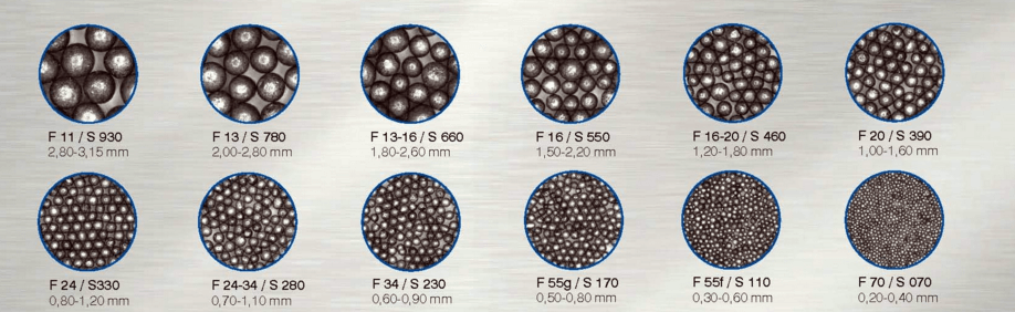
Bed Shot for the Mineral Jig
- Each individual ore property has its own set of circumstances that must be considered prior to determining the specific equipment requirements to successfully extract values from the ore. We offer the following as a suggested guide to consider when specifying / purchasing bedding for your Mineral Jig.Most jig shot normally consist of steel shot made from hardened steel balls, stainless or chrome alloy in sizes ranging from 1/16″ to 5/16″. We recommend when ordering balls from the manufacturer, you request their irregular product as precision, round shot is not absolutely necessary. Irregulars are usually much cheaper in price.
To determine the amount of shot needed for a particular jig, multiply bed length and width by the desired shot depth to obtain the cubic inches of the bed material needed. Use a bulk density of 0.167 lbs/cu in. as a guide to find total weight of shot for each bed of a duplex jig.
In general, the smaller the shot used, the finer the values that can be recovered. Smaller shot will also result in a reduced overall jig throughput capacity.
Example, a jig that normally uses 1/8″ shot could be modified to 1/16″ shot in order to recover values down to 100 mesh. The capacity of this same jig would then be reduced by at least 1/3 of its original throughput. The finer the shot (or bedding material) the finer and cleaner the hutch concentrate.
When jigging gold, silver and other metals, the feed should be preset so that the majority of anticipated gold particles reaching the screen will also pass through it. Balls should be nominally 0.030″ or larger than the bed screen opening. For larger nuggets anticipated in the overall recovery – a nugget trap should be introduced into the feed, prior to passing over the jig bed.
Shot having fractional, in-between sizes or made of stainless steel, lead or other compositions are also available. Ores that have a quantity of natural magnetite (iron ore composition) can be considered as a bed substitute. It does not rust and remains free working even if left idle for a time. It is economical since it naturally occurs in the ores being processed. Since magnetite particle sizes are not consistent, the throughput capacity of the jig could be compromised.
Recommended standard size balls for Jigs are: 1/16”, 1/8”, 3/16”, 1/4” and 5/16”. Corresponding screen sizes should be specified for each jig bed.
It is recommended that the throughput material size over the jig should be screened to 1/2” minus or as close to that size as possible. Anticipated nugget recovery above 1/2” should be arranged for prior to or during the screening process plus the above mentioned nugget recovery just prior to introduction to the jig.
- Mineral Processing Design by Baki Yarar, Z.M. Dogan
- Principles of Mineral Processing by Maurice C. Fuerstenau
- CONTRIBUTION TO THE MODELLING OF THE JIGGING PROCESS by Karantzavelos & Frangiscos
- Smart Dog Mining