
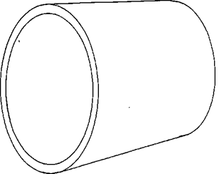
 The Mill Trunnion Liner fits inside the bearing to protect it from wear caused by the ore being washed over the liner and through the bearing as it is fed to or discharged from the mill.
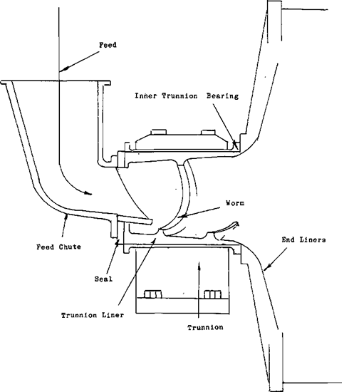
The difference in the trunnions at each end of the mill isn’t in the trunnions themselves. The trunnion liner on the feed end of the mill may have a WORM to assist the ore into the mill.
This worm acts like an auger or a screw. As the mill turns the spiral will pull the feed into the mill. Part of the feed chute will be a seal between itself and the mill. This seal is required to prevent spillage.
 |
 |
It is in the form of a plate with a circular hole cut in the centre of it. The seal is bolted over the end of the trunnion liner. This is to allow the feed chute to come down through this hole into the mill. The material that forms the seal will be attached around the hole. It may be made from rubber Teflon or maybe just plywood. The other half of the seal is connected to the feed chute. When the chute is in place the two halves of the seal come together holding the solids in the mill. This seal requires a fair amount of attention and up keep. With one half of the seal moving and the other half stationary, any grit and small rocks that get into the seal will cause a great deal of friction. This will wear the seal out rather quickly.
Trunnion Liner Schematics
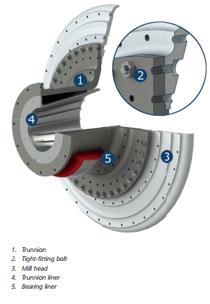
In most cases the trunnion liners are already mounted in the trunnions of the mills. If not, they should be assembled with attention being given to match marks or in some cases to dowel pins which are used to locate the trunnion liners in their proper relation to other parts.
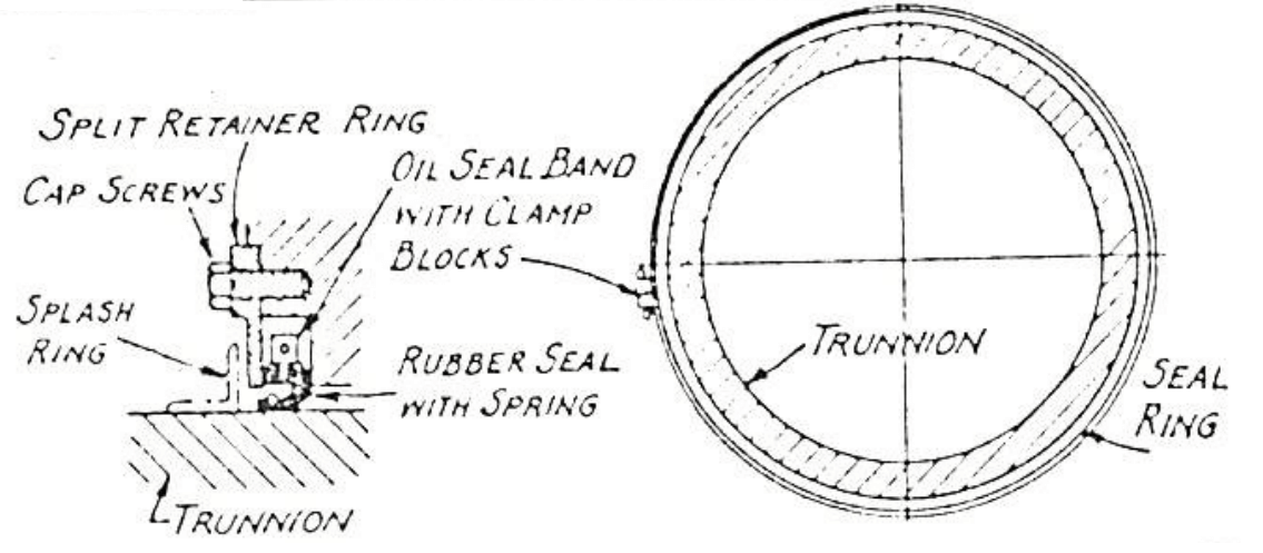
Assemble the oil seal with the spring in place, and with the split at the top. Encircle the oil seal with the band, keeping the blocks on the side of the bearing at or near the horizontal center line so that when in place they will fit between the two dowel pins on the bearing, which are used to prevent rotation of the seal.
Moderately tighten up the cap screws at the blocks, pulling them together to thus hold the seal with its spring in place. If the blocks cannot be pulled snuggly together, then the oil seal may be cut accordingly. Oil the trunnion surface and slide the entire seal assembly back into place against the shoulder of the bearing and finish tightening. Install the retainer ring and splash ring as shown.
BALL MILL FEEDER
If a scoop feeder, combination drum scoop feeder or drum feeder is supplied with the mill, it should be mounted on the extended flange of the feed trunnion liner, matching the dowel pin with its respective hole. The dowel pin arrangement is provided only where there is a spiral in the feed trunnion liner. This matching is important as it fixes the relationship between the discharge from the scoop and the internal spiral of the trunnion liner. Tighten the bolts attaching the feeder to the trunnion liner evenly, all around the circle, seating the feeder tightly and squarely on its beveled seat. Check the belts holding the tips and other bolts that may reduce tightening. The beveled seat design is used primarily where a feeder is provided for the trunnion to trunnion liner connection, and the trunnion liner to feeder connection. When a feeder is not used these connecting joints are usually provided by a simple cylindrical or male and female joints.
If a spout feeder is to be used, it is generally supplied by the user, and should be mounted independently of the mill. The spout should protect inside the feed trunnion liner, but must not touch the liner or spiral.
BALL MILL FEED BOX
Ordinarily the feed box for a scoop feeder is designed and supplied by the user. The feed box should be so constructed that it has at least 6” clearance on both sides and at the bottom of the scoop. The clearance is measured from the outside of the feed scope.
The feed box may be constructed of 2” wood, but more often is made of 3/16” or ¼” plate steel reinforced with angles. In the larger size mills, the lower portion is sometimes made of concrete. Necessary openings should be provided for the original feed and the sand returns from the classifiers when in closed circuit.
Horizontal and vertical joints should be provided for maintenance of the feeder. These joints should be designed with consideration for head room and accessibility.
BALL MILL GEAR GUARD
A plate steel gear guard is furnished with the mill for safety in operation and to protect the gear and pinion from dirt or grit. As soon as the gear and pinion have been cleaned and coated with the proper lubricant, the gear guard should be assembled and set on its foundation.
BALL MILL MANUFACTURING
We does not attempt to build a “cheap’ grinding mill. Engineering based on long experience with mill manufacture enters into the production of Ball Mills, with the result that in field operation this equipment yields the lowest possible operating costs, maximum operating time, and years of useful service. As such then it is not an expensive mill.
Every Mill is engineered and designed to meet the specific grinding conditions under which it will be used. The speed of the mill, type of liners, grate openings for ball mills, size and type of feeder, size and type of bearings, trunnion openings, mill diameter and length, as well as many other smaller factors are all given careful consideration in designing the Ball Mill.
Each mill is of proper design, constructed in a workmanlike manner, and guaranteed to be free from defects in material or workmanship. All Ball Mills are built to jigs and templates so any part may be duplicated whenever required. All parts are accurately machined for fits with close tolerances. Before shipment each mill is assembled in our shops, carefully checked and match marked to facilitate field erection. The mill is given a heavy coat of paint especially prepared for this type of machinery and all machined surfaces are thoroughly coated with protecting grease.
A complete set of detailed drawings is made for each mill and kept in a fireproof vault. This assures the future supply of perfectly fitting replacement parts for the life of the mill. Wearing parts embodying the latest developments are supplied on all orders.
Pages 14-19 are devoted to descriptions of many of the integral parts composing a Ball Mill. The discharge parts and the various feeders and drives are discussed on pages 20-23.
In these descriptions you will find the word “MEEHANITE”. This is a trade name for metal castings poured under a licensed agreement with The Meehanite Metal Corporation. A complete description of its characteristics and inherent nature is found on page 19.
The above heavy duty rolls developed for our own use provides a true circular shell having close tolerances. This assures perfect fit for shell liners and heads.
Ball Mill shells are fabricated from rolled plate steel. Under special conditions they can be cast of Meehanite, steel, or special alloys. The plate steel shells are rolled accurately to diameter and are welded according to ASME specifications, using a Union Melt Automatic Welding Machine. This equipment provides an even flow, uniform strength weld with full penetration.
On each end of the shell are steel flange rings bored to fit the shell, set in place and welded to the shell inside and out by the Union Melt machine. Large diameter shells are stress relieved under temperature and atmosphere control after welding is completed. Such heat treatment relieves any stresses or strains set up during rolling and welding operations.
The method of attaching the flange rings leaves the inside surface of the shell free from any pockets or depressions which would cause pulp racing and wear. The flanges are then machined true with the shell axis and with each other and counterbored to gauge for male and female fit with the separate mill heads. This construction eliminates any possibility of bolt shearing.
One or two manholes are provided in ball mill shells, designed so that all interior wearing parts can readily pass through such openings.
Ball Mill shells are generally 5″ to 7″ greater in diameter than the nominal mill diameter figure. In other words the diameter of a ball Mill is the measurement inside the average thickness of new liners—not inside the shell as designated by some manufacturers.
BALL MILL HEADS AND TRUNNIONS
Ball mill feed and discharge heads are detachable, cast of Meehanite metal of ample thickness, either of GA or GC, depending on the size of mill and with consideration to bending stresses. These heads are generally ribbed for extra strength and stiffness. Such ribs terminate near the center of the head in a trunnion seat. A male and female fit to the shell flange ring is provided and the back of the connecting flange is faced or spot faced to furnish a true seat for the joint connecting bolts.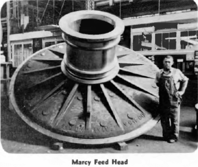
The head to which the gear will be attached has a seat or flange with a shoulder turned accurately to size providing a seat for the gear.
All turning and boring is done in one setting to assure perfect concentricity.
Smaller Ball Mills are constructed with separate trunnions; larger diameter mills have trunnions cast integral with the heads. Separate trunnions are attached to the heads with bolted flanges for male and female fit. Flanges are faced and counter bored. All trunnions are cast of Meehanite metal, turned and carefully polished. All trunnions have a large bearing surface capable of carrying the heavy mill load and to avoid heating during operation. The outer ends of the trunnions are faced and drilled to receive the trunnion liners, protecting the inside surface from wear.
Liner bolt holes are drilled to template and spot faced on the outside of the head.
MILL FEED HEAD
The feed head has ample depth to contain the feed head liners. The rod mill feed head is conical in shape to give the essential feature of a feed entry pocket in front of the rods.
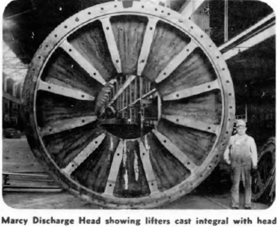
BALL MILL DISCHARGE HEAD
This head is of considerable depth providing a pulp lifting chamber, and is designed to contain the discharge grates, clamp bars, and the lifters which elevate the mill product through the trunnion. See pages 20 and 21.
ROD MILL DISCHARGE HEAD
For rod mill work the discharge head is conical in shape causing the rods to travel by rotation laterally and away from the exceptionally large discharge opening. The discharge opening is larger than the inlet opening, thus providing the ball mill Low Pulp Line principle of grinding.
TRUNNION LINERS
The discharge trunnion liner is cast of Meehanite metal and has a wide mouthed bell to conduct the mill product away f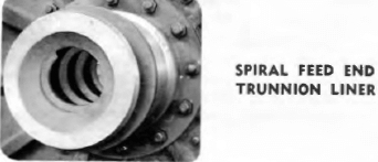 rom the mill, with no back drip.
The feed end trunnion liner is also constructed of Meehanite and can be furnished of several designs to meet each specific application. For normal closed circuit grinding work a spiral liner is furnished to screw new feed and return sands into the mill. For spout fed mills a plain tapered liner is generally furnished.
The mill trunnions are machined with a taper bored seat to receive the trunnion liner. Such arrangement permits the trunnion liner weight to be carried by the seat rather than by the connecting studs. This is of particular importance on the feed end since the shearing effect of the added feeder would cause breakage of the feeder connecting bolts.