
The testing of tonnage lots of ores and industrial materials by continuous Mineral Processing Pilot Plant operation is in many instances advisable before a full scale milling plant is installed. The treatment of complex ores by new processes or by the use of new or unusual reagents in flotation may involve problems the effect of which should be studied under small scale continuous operating conditions.
The milling of ores by fine grinding and flotation requires the establishment of closed circuits where middling or unfinished products are returned to various points in the flowsheet for additional treatment. Where unusual flotation reagents are used, or when an intricate flowsheet is required, the effect on the operation is not satisfactorily determined from batch laboratory tests.
Commercial operation of the cyanidation process for the treatment of gold and silver ores involves the continuous re-use of much of the cyanide solution after removal of the dissolved gold or silver by precipitation. This introduces the problem of the dissolution of undesirable base metal salts especially when complex or partially oxidized ores are treated. These salts may build up in the solution and act as cyanicides to affect the rate of dissolution of the gold or silver by cyanide and also affect the efficiency of prescription methods.
The milling of complex ores may require the use of combined methods of treatment such as gravity concentration and flotation, or coarse flotation followed by slime flotation, or gravity and amalgamation followed by cyanidation.
The continuous Metallurgical Processing Pilot Plant test offers ample opportunity for the study of all such problems under the same conditions as would exist in a large milling plant. The results thus secured will eliminate the need for costly experimentation with large tonnages of ore when the commercial plant is placed in operation, and assures selection of the proper size and type of equipment. It also affords an excellent opportunity for the operating personnel of the proposed milling plant to become familiar with the various problems which are presented by the ore treatment. The determination of the best method of feeding certain reagents, the effect of various pulp densities upon the mechanical handling of the pulps, and the solution of other unforeseeable problems, will greatly facilitate smooth operation of the proposed plant.
911metallurgist.com has maintained a complete continuous Pilot Plant Equipment for several years. The operation of this plant on numerous classes of ores, both metallic and non-metallic has provided much information on the various functions of pilot plant operation. Besides offering its facilities to many operators for continuous pilot plant tests, it has served as a practical demonstrator for those who desire to plan their own pilot plants.
On the basis of the experience obtained in our own testing plant, and in supplying equipment for hundreds of ore testing laboratories, the following information is submitted to aid in planning the installation of a pilot plant.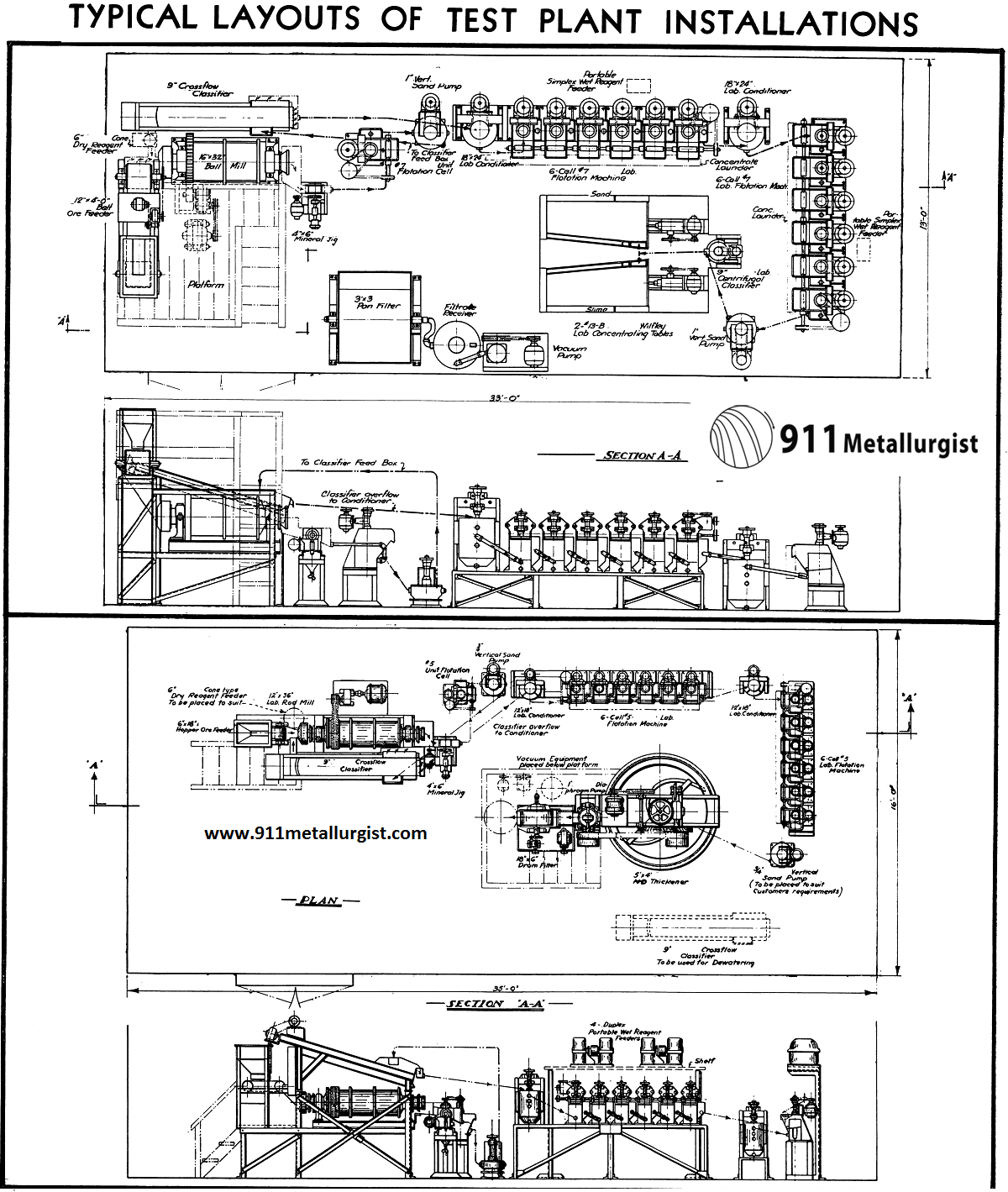
Types of Pilot Plant Installations
The establishment of pilot plants in the mineral industry falls into two general divisions.
- Pilot plants for the use of schools of mines, mining bureaus and private companies where extreme flexibility is required for testing numerous ores by different flowsheets.
- Larger tonnage pilot plants for mining and milling operations where extensive testing of ores of the same general character is to be conducted. Equipment of such pilot plants is available in several different size ranges, a general list of which is shown on the final page of this article.
Selection and Arrangement of Pilot Plant Equipment
The equipment for the proposed pilot plant should be selected to secure operating conditions which will be the same as in a regular milling plant. The arrangement of the equipment should allow maximum flexibility for changing the flowsheet.
Pilot Plant Crushing and Sampling Equipment
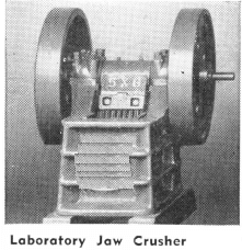
The crushing equipment should be in a separate room to eliminate dust in the main ore dressing section. The type and size of crushing equipment selected depends upon the type of product required for subsequent treatment. In general crushing to minus 1/8″ for the 12″ diameter ball mill and minus ¼” for the 16″ diameter ball mill are desirable. Larger size ball mills may take feed crushed to minus 3/8″ or minus ½”.
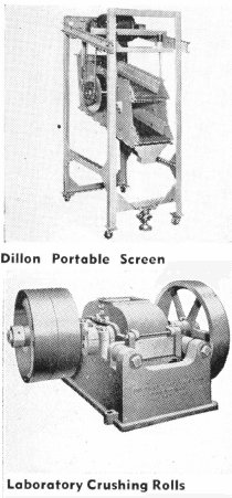
Secondary crushing by means of rolls is generally preferred in this type of plant because of the high capacity, less head room required, and simplicity of cleaning. The Vibrating Screen is highly recommended for the screening operation because of its portability, large capacity and efficiency. It can be furnished as a totally enclosed unit to minimize the dust nuisance.
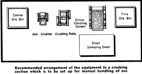
Manually Operated Equipment
In pilot plants designed to treat small quantities of different ores it is usually considered best to leave the crushing section arranged for manual handling of ore, with all of the equipment on one level. This arrangement has the advantage of being easier to clean up after each lot of ore, requires less equipment, and can be installed without expensive supporting framework.
The disadvantage is that of requiring considerable hand labor shovelling the crude ore into the crusher, the crushed ore onto the vibrating screen, the screen oversize into the rolls and the rolls product back onto the screen. In addition, the sampling must be done by hand, the finished product carried to the ore feeder in the grinding section. The floor should be made of cement into which anchor bolts for the machines may be grouted.
The finished product is most conveniently sampled by placing every 5th or 10th shovel of product onto a coned pile on a steel sampling plate as the material is being transferred to the fine ore bins. The sample thus produced is thoroughly mixed and again fifth shovelled, and the final sample further reduced by means of the Jones Sample Splitter.
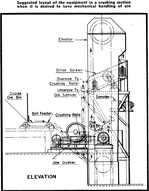
Mechanically Operated Equipment
In cases where a considerable quantity of ore is to be tested and if it is desired to reduce hand labor to a minimum, the crushing section can be equipped with ore bins, elevators and samplers, the same as in a large milling plant.
Pilot Plant Grinding Circuit
Elevation of Grinding Section
The ore feeder should be placed high enough to permit feeding by gravity to the ball mill or to any machines which may be used for pretreatment ahead of the grinding circuit.
The ball mill and classifier are installed on an elevated platform to obtain gravity flow of the ball mill discharge to the Jig or Unit Cell, which is placed on the main floor level.
Closed Circuit Piloting
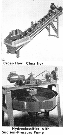
In order to obtain maximum flexibility for test plant purposes the ball mill classifier circuit should be closed by using a Vertical Sand Pump. The ball mill discharge is pumped to the classifier, which permits placing the classifier high enough to give gravity flow of the classifier sands to the ball mill. An important advantage of this arrangement is that the classifier slope can be changed as desired without interfering with the flow of return sands to the ball mill. A drum type feeder is recommended for the ball mill to eliminate the splash and waste which usually occur when using a scoop feeder and feed box.
Pilot Ball Mill Capacity
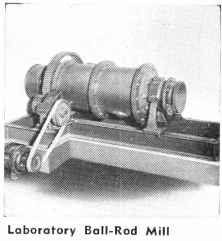
In pilot plants which test various types of ores it is frequently necessary to obtain an extremely fine grind. The added capacity of the grinding circuit necessary to produce a finely ground ore pulp is most conveniently secured by mounting the grinding mill on an adjustable steel frame to allow for an increase in the length of the mill. Extra shell sections can be added to most Ball Mills, so that when a fine grinding problem is encountered the mill can be doubled in length without expensive changes in foundations and, within the limits of the power of the driving motor, without change of drive.
Ore Feeders
In most pilot plants, particularly those treating just one type of ore, the Hopper Type Ore Feeder is considered very satisfactory. This unit has an adjustable gate to regulate the amount of ore fed onto the belt which travels under the hopper.
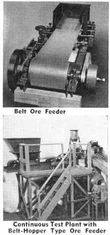
However, a uniform rate of feed on small tonnage can best be obtained with a belt feeder. The belt feeder is particularly desirable if damp, sticky ore is to be handled or if the plant is to be used for testing a wide variety of ores.
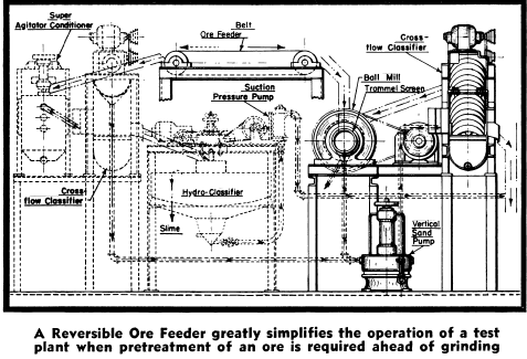
The first step in ore treatment generally consists of grinding and classification of the ore preparatory to various concentration or chemical treatment processes. However, it is sometimes desired to subject the crushed ore to gravity concentration, blunging, log washing or desliming before grinding. In these cases the operation is greatly simplified if the travel of the feeder belt can be reversed, to permit feeding the ore direct to any desired pretreatment equipment. The Belt Ore Feeder for pilot plants can be equipped with a reversible drive. The Hopper Ore Feeder is a small unit which can be easily turned around to reverse the direction of feed.
Controlling the Rate of Feed
Mechanical feeders are easily installed for delivering a large tonnage of ore to a belt feeder from the fine ore bin of a mechanically operated crushing and sampling plant.
Where a manually operated crushing and sampling plant is installed, the feeding of the ore must be by hand. If a hopper type feeder is used the rate of feed is regulated by the adjustable hopper gate. The desired feed rate can easily be obtained by feeding weighed amounts of ore at various openings of the gate until the correct setting is secured.
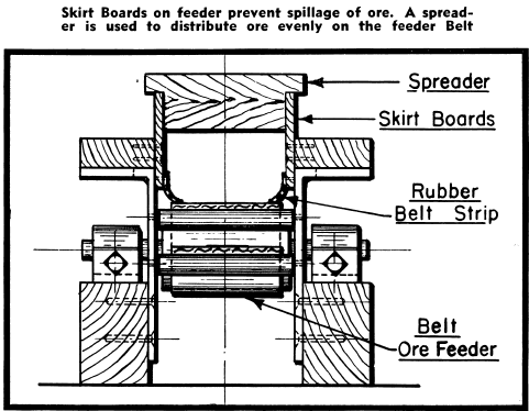
Where a belt type feeder is used a constant and accurate rate of feed may be secured by the following method. The speed of the belt, which should be adjustable, is set at a slow speed of about 18 lineal feet per hour. Two adjustable skirt boards made of 1″ x 4″ or 1″ x 6″ lumber are placed over the belt and fastened to supports, allowing just a small clearance between the belt and the lower edge of the board. These prevent ore spillage and provide guides for a spreader.
Assume it is desired to treat 200 pounds of ore per hour. Make a spreader out of wood to fit between the skirt boards and with protruding guides to slide along the top edges of the skirt boards. Make the spreader of proper depth to distribute 66 2/3 pounds of the crushed ore over six feet of the belt. This will give an accurate feed rate of 200 pounds per hour.
A flagged marker riding on the ore can be used to show the position of the ore on the belt without close inspection.
Recovery of Minerals in the Grinding Circuit
One of the basic principles followed in any milling plant is to “Remove the mineral as soon as it is free.” For this reason almost all pilot plants are equipped with a Mineral Jig and a Unit Flotation Cell to investigate the possibility of making a high grade concentrate from the partially ground ore in the grinding circuit.
Pilot Mineral Jig
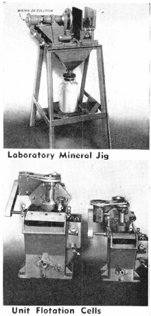
The Mineral Jig was developed to recover a high grade gravity concentrate from a partially ground and unclassified ball mill discharge before the mineral had been ground to a slime. Heavy gravity minerals and metals such as galena, wolframite, scheelite, cassiterite, cerussite, and metallic gold or silver will circulate through the classifier and ball mill until ground to very fine particles unless removed from this circuit. The Jig accomplishes this removal and the importance of this method of concentration cannot be over-emphasized.
Any ore containing high gravity mineral should be tested by a Mineral Jig. Gold ores being treated by flotation or cyanidation generally contain gold particles which are easily removed from the grinding circuit by the Mineral Jig with a high ratio of concentration. This concentrate may be subjected to barrel amalgamation and the recovered gold produced in bullion form.
Mineral Jigs suitable for treating ball mill discharge in pilot plants are available in the 1-M laboratory size for treating 50 to 150 pounds per hour, the 4″ x 6″ for treating 200 to 500 pounds per hour, and the 8″ x 12″ for semi-commercial size plants.
The Mineral Jig may also be used as a cleaner jig where it is desired to produce a small amount of final concentrate with unusually high ratio of concentration. For instance, it may be used to retreat rough concentrates produced by the 4″ x 6″ Mineral Jig with the cleaner tailing product being returned to the rougher circuit for retreatment.
Pilot Flash Flotation Cell
Unit Cell Flotation is an operation which has been developed by Equipment Company to secure a yield of rich concentrate from ores as they are being ground for final treatment. The Unit Cell is constructed to withstand the abrasive action of the partially ground pulp in the ball mill discharge.
Operation of the Unit Cell is one of the easiest and most productive processes in flotation. The necessary flotation reagents are generally fed with the ore to the ball mill. The ball mill discharge, with some dilution water added, passes through the Unit Cell. A scalping screen through which the ball mill discharge passes is recommended to prevent tramp oversize from collecting in the cell. Special sand relief openings are provided in the cell to allow the discharge of the ordinary coarse sand in the pulp.
The size of Unit Cell recommended for pilot plants is generally the same as that of one of the cells of the flotation machine in the regular flotation section.
Mineral Jig and Flash Flotation Cell
There are some cases where both the Jig and Unit Cell may be used to good advantage in the grinding circuit. For example, the Jig and Unit Cell have been used for treating complex lead-zinc ores, producing lead concentrates with a lower zinc content than was obtainable by flotation alone. Many gold ores contain a fraction of the gold present as a free mineral and the balance associated with oxide minerals or partially oxidized or tarnished sulphides. In such cases the Jig can be used to remove the free gold, and the Unit Cell to recover the sulphides at a coarse mesh.
Pilot Flotation Circuit
The flotation section of the pilot plant comprises the conditioners, rougher flotation machines, cleaner flotation machines, reagent feeders, sand pumps, concentrate thickeners, and filters.
Gravity flow of the ground ore pulp from the grinding section through the flotation section is possible when the ball mill and classifier are elevated as described under Grinding Section, Elevation.
Flotation Conditioners
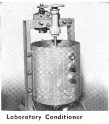
Conditioning of the pulp before flotation is an important operation as it provides an even feed to the flotation circuit and premixes the various reagents. The more nearly even the feed to flotation, the better the results obtained. The Conditioner is provided with outlet pipes at different levels so that the capacity can be varied to secure different conditioning times. Conditioners may be selected from a variety of sizes to best fill the requirements of the flotation section. A conditioner should be provided for each bank of flotation cells. The conditioner, being a self-contained motor driven unit, is portable and can be used in any place in the plant as a mixer or repulper.
Flotation Machines
The number of banks of rougher cells needed will depend upon the nature of problems to be encountered. Two banks of cells with six or eight cells to each bank can be used to produce separate concentrate in differential flotation work. A third bank of cells, to be used as standby cells for extra cleaning or for occasional need to produce a third concentrate, will be found very useful.
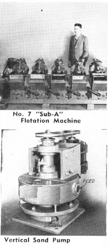
“Sub-A” Flotation Machines for test plants are available in three cell sizes. The No. 5 machine contains a pulp volume of 0.29 cu. ft. per cell when filled to operating pulp level without the machine running. The No. 7 cell measured under the same conditions has a volume of 1.11 cu. ft. and the No. 8 a volume of 2.75 cu. ft. The actual pulp volume in the machines where the pulp is agitated with frother is considerably less because of the displacement by air bubbles. Capacity varies with the flotation time required for different ores.
Reagent Feeders
Flotation reagent feeders for pilot plants have been developed by Equipment Company which are capable of accurately feeding small quantities of reagents. Wherever possible in the pilot plant it is desirable to feed all reagents in liquid form which allows closer control than feeding solids.
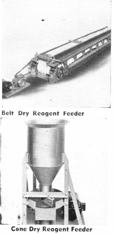
The feeding of most reagents which are required in quantities more than a few drops per minute is accurately performed by the Portable Wet Reagent Feeder with micrometer control. Reagents required in quantities as low as one drop per minute are most accurately fed by the bent tube attachment which has been perfected in the Equipment Company Test Plant. This attachment can be operated by any of the Equipment Company disc type feeder mechanisms by removal of the cup disc and attaching the dipper tube to the shaft.

Insoluble dry reagents may be fed by either the cone type or belt type dry reagent feeder. Dry reagents used in very small quantities are usually most conveniently and accurately fed by the belt type feeder. This arrangement is similar to that described for the ore feeder in the grinding section.
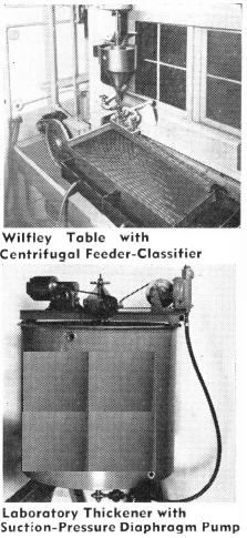
Pilot Plant Thickeners
Thickeners and Filters for pilot plants are built in small units that embody the same principles as those in the commercial size units. Thickeners having various diameters from 3 feet up to those of commercial size units are available. Two convenient sizes for small pilot plants are the 3 ft. diameter by 3 ft. depth and the 6 ft. diameter by 3 ft. depth. These units have the regular Equipment Company spiral rakes and ¾” Suction-Pressure Pump for removal of the thickened pulp. They are motor driven self-contained units which are easily portable and can be set up at any desired point in the plant. Special shallow tray thickeners for handling extremely frothy materials can also be supplied.
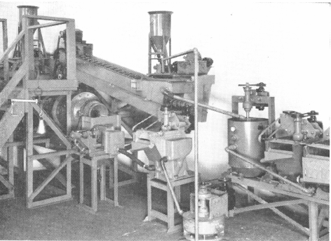
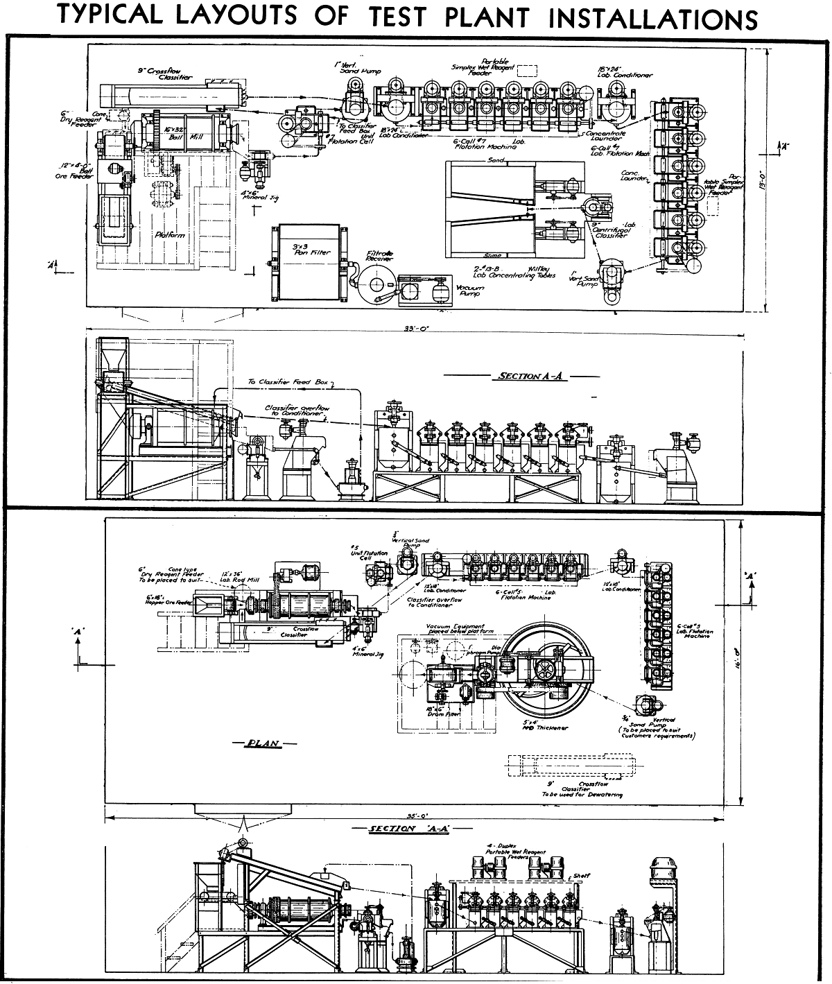
Typical Continuous Test Plant installation showing closed grinding circuit with jig and unit cell and gravity flow from classifier to flotation circuit
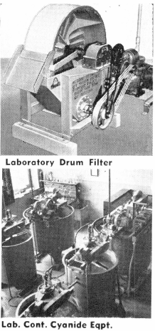
Pilot Test Filters
Filtration for pilot plants is generally handled by the Rotary Drum Filter. This filter is available in sizes ranging from 18″ diameter x 6″ face up to commercial size units. For pilot plants having a capacity up to 500 pounds per hour the 18″ x 6″, 18″ x 12″, or 36″ x 12″ are ordinarily used. The size to be used is of course dependent upon filtration rate of concentrate and quantity to be filtered.
In addition to the drum type filter, there is also available the Pan Filter which is a very desirable unit for filtering large samples of pulp or for filtering tailing product when desired. A duplex unit, with two pans which can be alternately filled and discharged, can be made to serve as a continuous filter for the smaller pilot plant installations.
Vacuum pumps, receiver tanks, filtrate removal pump, and pressure pump for cake discharge from the continuous filters are necessary auxiliary equipment for filtration section.
Gravity Concentration Pilot Circuit
The equipment for gravity concentration in the present day pilot plant is generally confined to those units which are used in conjunction with flotation or cyanidation. The two units which may be considered indispensable for the up-to-date pilot plant are the Mineral Jig and the Wilfley concentration table.
Mineral Jig
The Mineral Jig is generally used in closed circuit with the ball mill and classifier as discussed under Grinding Section. However, the Jig may be used in open circuit when grinding is done in open circuit, or when fine crushing, without grinding, is employed.
Wilfley Concentrating Tables
Gravity table concentration is often used in pilot plants to recover non-floatable mineral from flotation tailing. Tables may also be used as primary concentrators in which case they are generally used in conjunction with the hydraulic sizing classifier. The equipment available for gravity table concentration in pilot plants includes the No. 13A table having deck dimensions 40″ x 18″, the No. 13B Table having deck dimensions of 50″ x 24″ and the No. 12 table which has a deck dimension of 7’8″ x 3’11”.
Table feed may be hydraulically sized in the Laboratory Hydraulic Classifier which has classifying chambers 4″ x 4″.
Cyanide Leaching Pilot Testing
The operation of the continuous pilot testing plants for treatment of ores by the cyanidation process is not so commonly practiced as is that of testing by flotation. However, the pilot plant built for flotation testing can readily be converted into a cyanide treatment plant since equipment for crushing and grinding the ore would be the same. Laboratory agitators and thickeners similar in design and operation to standard machines are available. The agitators are built in various sizes to fit the capacity requirements of pilot plants.
Another satisfactory method of pilot plant testing by cyanidation is by use of the Batch Cyanide Plant which is built for cyanidation of small lots of ore or concentrate. This plant which consists of a combined agitator and thickener tank and storage tanks for solutions and precipitation apparatus is necessarily intermittent in operation but the results secured from re-use of the solutions is comparable with those from a continuously operated plant.
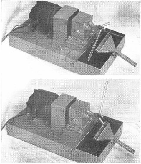
Special bent tube dip attachment developed in Lab. for accurately feeding a very small quantity of reagent. The end of the tube fills with reagent through a small hole made in the glass. The quantify of reagent fed depends upon the distance between the hole and the bottom of the tube.
Auxiliary Pilot Plant Equipment
One of the most important pieces of auxiliary equipment is the Vertical Sand Pump. This pump is a motor driven self-contained unit which is easily portable and requires no floor foundation. It pumps frothy concentrate as well as coarse sand products and will operate upon fluctuating flows of pulp. This pump is available in size ranges from three-fourths-inch to large commercial plant size units.
A tank for constant head water supply is advisable since the small flows of pulp require accurate control of the water supply. The Bolted Steel Tank has proven to be very satisfactory for this purpose. It can be easily assembled in any location and is free from leakage.
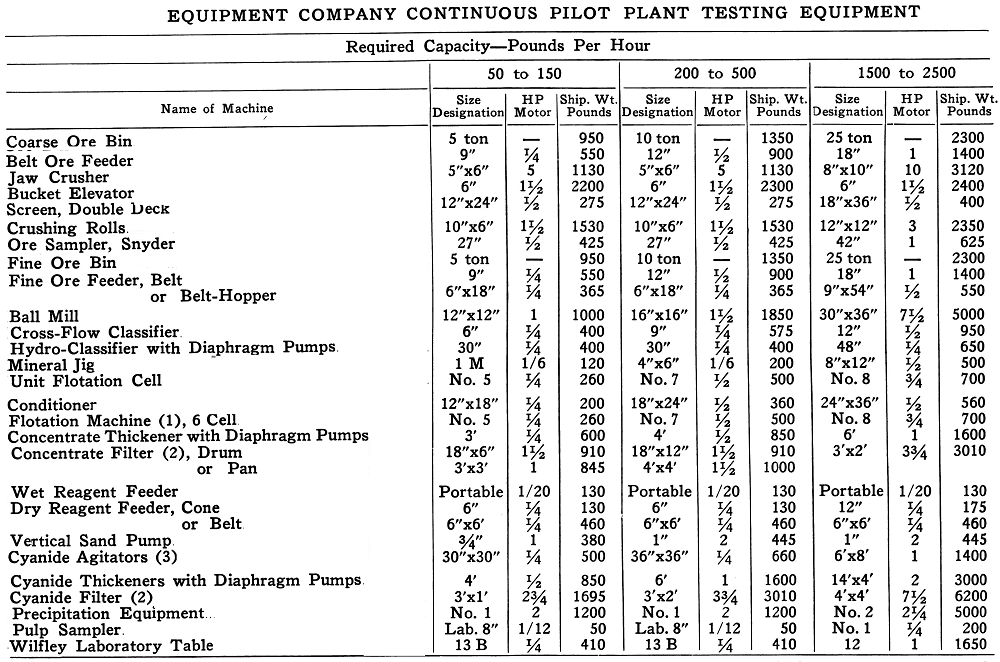
- Multiple banks to be used depending on problem
- Includes necessary vacuum equipment
- At least two preferably three. Includes steel tank. Sizes shown in this table are for estimating only. Exact requirements will depend on many factors including grindability of ore, fineness required, flotation time and densities, ,settling and filtering characteristics.
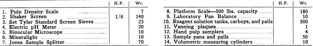
Following is a list of instruments and small equipment necessary in producing the desired data from the testing operation:
Source: This article is a reproduction of an excerpt of “In the Public Domain” documents held in 911Metallurgy Corp’s private library.