
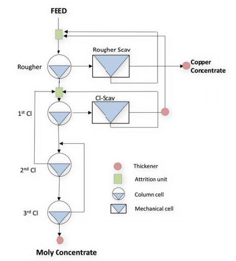
The copper-moly separation circuit was modelled using the test kinetics. The circuit was configured to include columns in every stage in order to minimize the amount of entrainment and to maximize the washing effect of the molybdenum concentrate.
The circuit was designed with long retention times so that it could be operated with a slow pulling rate to allow the copper to drain back into the pulp inn order to attain high moly concentrate grades. The circuity was configured with 33 cleaning stages. However, with the kinetics obtained during the tests, it appears that two cleaning stages will be sufficient, provided the 1st cleaner tails is re-circulated back to the roughers. Due to the high fluctuations in the moly feed grade, it is considered prudent to have the third cleaner built into the circuit from the start of the operation.
In addition, testwork suggests that the rougher feed and 1st cleaner feed slurry undergo good agitation conditioning. It is also recommended that the 1st cleaner scavenger tail, a bearer of large amount of water, bee thickened to say 40% solids to dewatered the circuit for re-use within the circuit or too send it too the internal reclaim water system. It is envisioned that all columns will operated with desalinated water as washwater for the concentrate. The system will operate with nitrogen in all cells and columns and use CO2 gas for pH adjustment.