
The size of mechanical classifier required for a particular job depends on the following factors:
- Tons of dry solids to be overflowed per 24 hours. This is simply a predetermined tonnage.
- Mesh size at which separation is to be made. The mesh size is determined by laboratory tests or is already known from previous experience.
- Density desired in the overflow. This is dependent upon subsequent treatment.
- Settling rate of solids, of the size at which separation is desired, in pulp of the particular density of the proposed installation. This is determined by laboratory settling tests.
Overflow Capacity of the Mechanical Classifier
If the settling rate has been determined by laboratory tests the classifier pool area required is obtained from the following formula:
Effective pool area, sq. ft. = Vol. overflowing, cu. ft. per min/Settling rate, ft. per min.
This is the best method of determining the required pool area. However, if settling tests have not been made and it is inconvenient to make tests, the following procedure, which has been proved to be entirely satisfactory, may be used.
Table I gives the overflow capacity, per sq. ft. of classifier pool, in tons of dry solids and in cu. ft. of pulp per 24 hours, for various pulp densities and different mesh separations.
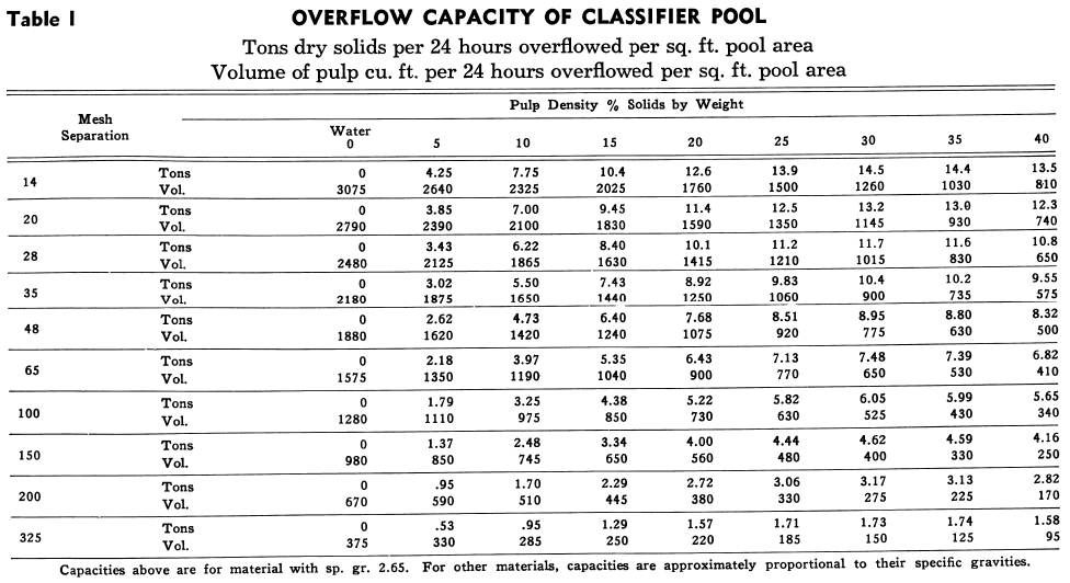
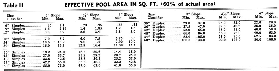
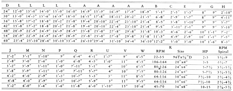
Table II gives the minimum and maximum effective pool area in sq. ft. of Cross-Flow Classifiers, at various slopes of the classifier.
Example: Assume it is desired to overflow 100 tons of dry solids per 24 hours at 65 mesh in a pulp of 20 % solids. Table I shows that 6.43 tons will overflow per sq. ft. of effective pool area. Therefore, to overflow 100 tons in 24 hours, a classifier with 15.5 sq. ft. (100 divided by 6.43) effective pool area would be required.
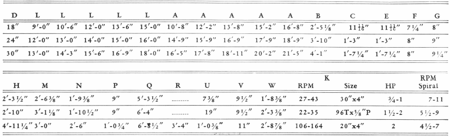
For a 65 mesh separation it is preferable to set the classifier at 3½” slope. Table II shows that at 3½” slope the 30″ Cross-Flow Classifier has an effective pool area from 12.9 to 16.4 sq. ft. depending on the height at which the weir is set. Therefore the 30″ classifier would be the proper size for the overflow capacity desired.
Sand Conveying Capacity
The sand conveying capacity must next be considered.
Table III gives the sand raking capacity and recommended conveyor speeds for various mesh separations.
Assume there is to be a circulating load of 250%. Then the conveyor must handle 2½X100 tons, or a total of 250 tons per 24 hours.
Table III shows that at 65 mesh a peripheral speed of 44 ft. per min. is recommended, which on the 30″ classifier corresponds to 5.6 R.P.M. At this speed the 30″ classifier will convey 275 tons of solids per 24 hours, which then is ample for this job. Therefore, this size Cross-Flow Classifier will satisfy all the requirements of this problem.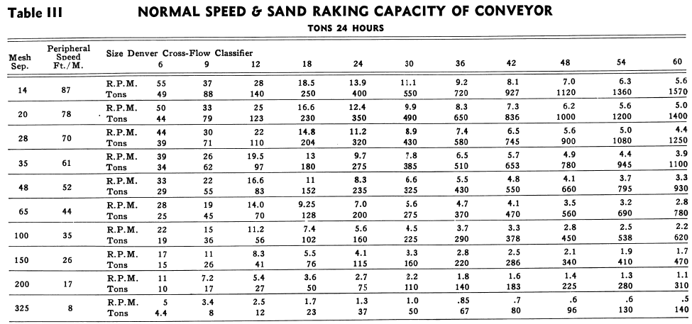
But, suppose the circulating load required was 300% instead of 250% specified above. The amount of sand to be raked would be 300 tons per 24 hours. In this case it would be necessary to speed up the conveyor of the 30″ classifier above the normal speed of 5.6 R.P.M. in order to handle the 300 tons of sand. In speeding up the conveyor more agitation is produced in the tank and settling is interfered with, resulting in a slightly coarser overflow. In this case it might be necessary to provide a 36″ classifier.
Length of Classifier Tank
If the classifier is to be used in open circuit it may be the shortest standard length made in that particular size.
For installation in a closed grinding circuit the classifier length must be pre-determined to assure that it will close circuit with the ball mill. This is entirely a mechanical problem and the correct length is determined by making a ball mill-classifier layout to scale.
The pool area varies with the slope and since capacity at a required mesh depends on pool area, the slope cannot arbitrarily be changed to accomplish a closed circuit. With the classifier size and slope established it is necessary to make the classifier of sufficient length to close the circuit.
Mechanical Classifier Installation & Operations
Classifier Slope
In general the classifier should be installed with a slope of from 3″ to 4″ in 1 ft.
The steeper the slope the less the pool area of a given size classifier. The less the pool area the less the capacity. The maximum capacity for any mesh separation is obtained at a slope of about 3″ in 1 ft. But, for very coarse separations it may be necessary to increase the slope and thus decrease the pool area so as not to cause overloading.
Recommended Slopes:
65 to 150 mesh………………………………………………3″ per ft.
48 to 100 mesh………………………………………………3¼” per ft.
35 to 65 mesh………………………………………………..3½” per ft.
28 to 48 mesh………………………………………………..3¾” per ft.
14 to 35 mesh…………………………………………………4″ per ft.
Install a Classifier in Closed Circuit Grinding
In selecting equipment for closed circuit grinding, a ball mill-classifier layout should be made and classifier size and ball mill scoop radius made to conform to this layout.
The launder from ball mill discharge to the classifier should have a slope of about 1″ per ft. depending on fineness of grind and pulp density. The launder from sand discharge of the classifier to the ball mill scoop box should have a slope of from 4″ to 6″ per ft.
Spiral/Screw Classifier Speed
The speed of the conveyor should be just sufficient to handle the sands to be removed. The slower the speed the less the agitation in the pool and the finer the overflow. The lower the speed the longer the life of the classifier and all wearing parts.
When and Where to use a Screw-Spiral Classifier
Closed Circuit Ball Mill or Rod Mill Grinding
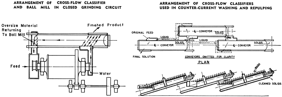
Most efficient grinding is effected by removal of material from the ball mill as soon as it has been reduced to the required size. This eliminates over-grinding and permits utilizing all of the power applied to the ball mill in actually grinding the oversize material. This may be accomplished by using the Cross-Flow Classifier in closed circuit. The entire ball mill discharge goes to the classifier which separates the material ground to the desired size; returning the oversize material to the ball mill.
The Cross-Flow Classifier is ideal for this closed-circuit work. Its exclusive “Cross-Flow” principle of operation results in an extremely accurate separation. Various lengths of this classifier and variation in slope make it possible to fit the classifier to the circuit without use of expensive, troublesome equipment such as elevators, pumps, etc.
In closed grinding circuit separations are easily and efficiently made at from 20 to 100 mesh sizes. Normally, it is considered best practice to use a Hydroclassifier for separations at 100 mesh and finer. Efficiency of separation in fine mesh range requires a very large pool area. Thus, the Hydroclassifier, with its large surface area gives more efficient classification, more economically, than is possible with a “spiral” classifier.
Sand-Slime Separations
Separating slimes from sands, prior to subsequent treatment of either or both the sands and slimes, is often required preliminary to leaching, tabling, cyanidation, etc.
Usually such separations are made on dilute pulps with a relatively small amount of slimes. Under these conditions a mechanical classifier can make efficient separations at a much finer mesh than in a closed grinding circuit where there is a higher density pulp and larger percentage of fines. The Cross-Flow Classifier will efficiently handle sand- slime separations in the range from 150 to 325 mesh, with a minimum amount of dilution water.
Dewatering
The Cross-Flow Classifier provides an efficient means of dewatering sands and concentrates or other granular material. A common application in this work is when the granular material is difficult to handle in a thickener. Also in many cases, where tonnage is not large, classifiers are considerably more economical than a thickener-filter installation lower in first cost lower in operating and maintenance costs require practically no attention.
Continuous Counter-Current Washing
A very common application of classifiers is in washing granular material to remove reagents, liquors, etc. Classifiers have the same advantage on small tonnage as in the case of dewatering lower initial and operating costs and less attention required. The particles to be washed pass successively up the inclined tanks of several classifiers, while the wash passes through the classifiers in the opposite direction. In each classifier the pulp is diluted, mixed and rabbled, the particles washed, and the liquid removed resulting in a thoroughly washed and cleaned final product.
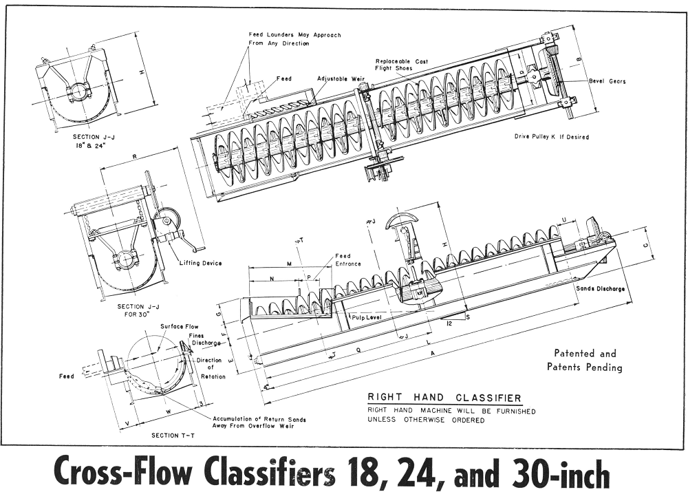
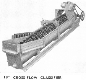
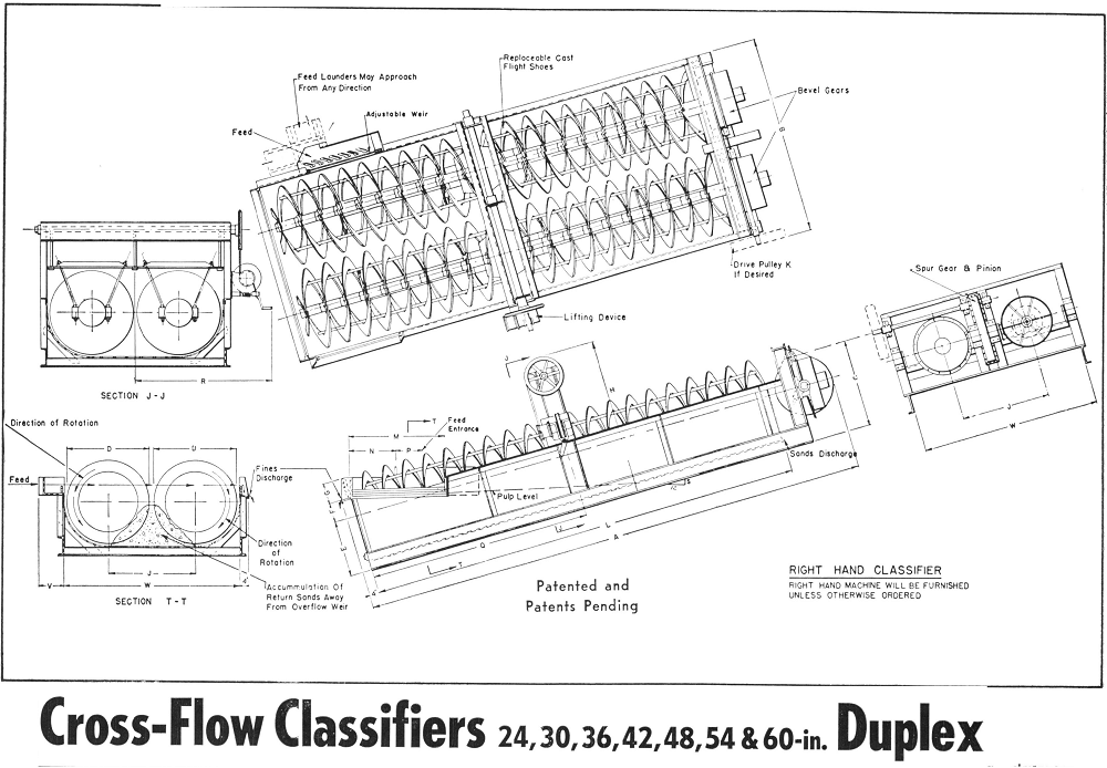
Cross-Flow Classifier Design
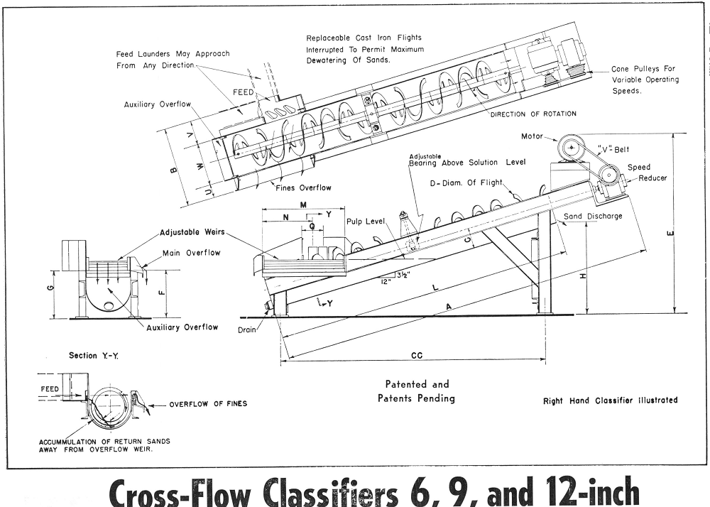
STAND: For convenience in installing, these smaller sizes are provided with steel legs. The stand is made to give the most commonly used slope of 3½ inches per foot.
SHAFT: Solid, square steel.
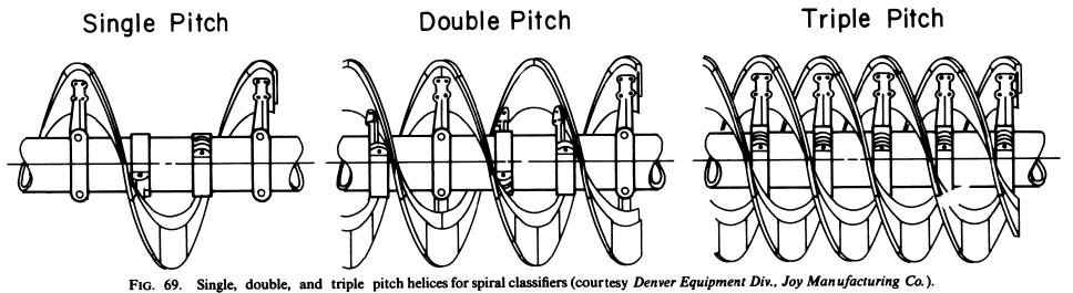
FLIGHTS: Hard, cast iron; made in short segments which fit over the square shaft. Flights may be placed on shaft so that blades form a continuous “spiral,” or may be staggered to obtain an interrupted “spiral.”
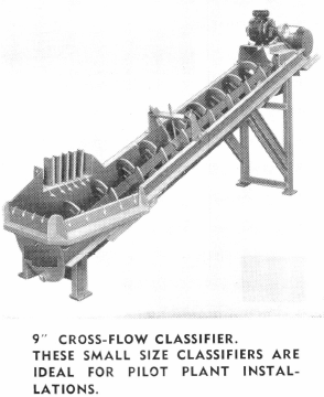
DRIVE: Enclosed worm-gear speed reducer driven by motor through V-belts; cone pulleys are used to permit speed variations desirable in experimental laboratory or pilot plant work.
SHAFT: Heavy steel pipe.
FLIGHTS: Hard, cast iron; made in short sections; bolted to cast iron arms which are carried on the shaft. Easily replaceable without draining tank.
DRIVE: Bevel gear driven by gearmotor through sprocket and chain. Speed of drive is determined by the requirements of each installation. A variable speed drive may be furnished, at extra cost, if desired.
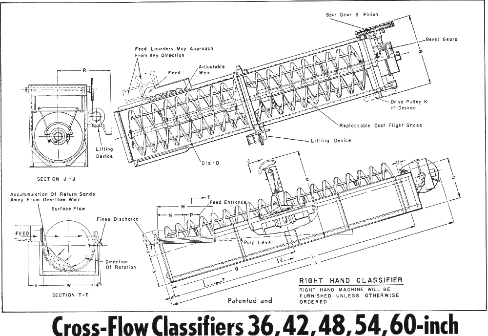
SHAFT: Heavy steel pipe with steel reinforcing sleeve at the lower bearing.
FLIGHTS: Steel plate; bolted to cage which is carried by steel pipe shaft. Hard, cast iron wearing shoes, made in short sections, are bolted to the steel flights and are easily replaceable without draining the tank.
DRIVE: Cast steel bevel gear and bevel pinion driven from a countershaft through spur gears; gearmotor and V-belts to countershaft. Speed of drive is determined by requirements of each installation. Variable speed drive may be furnished, at extra cost, if desired.
SHAFTS: Same as for corresponding sizes of simplex classifiers.
FLIGHTS: Same as for corresponding sizes of simplex classifiers.
DRIVE: Heavy cast steel bevel gears and bevel pinions, driven from countershaft through heavy spur gears; gearmotor and V-belt or chain drive.
LIFTING DEVICE: Same as for corresponding sizes of simplex classifiers.
CONVEYOR ROTATION: The two helical conveyor flights rotate in opposite directions, thus conveying the sands up the center of the tank giving free drainage back along both sides of tank.
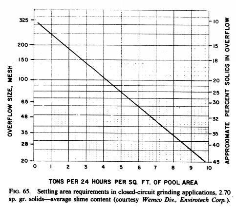
Classifier Settling Area Requirements
Source: This article is a reproduction of an excerpt of “In the Public Domain” documents held in 911Metallurgy Corp’s private library.