
Table of Contents
As part of its effort to reduce the need for strategic minerals through conservation and to reduce the capital and energy requirements of mineral processing, the Bureau of Mines has investigated a method for preparing ferrochromium alloys containing less than 2 percent carbon. This method will conserve chromium and should reduce the capital and energy requirements for chromite reduction.
Reduced products containing less than 2 wt-pct C and as low as 0.01 wt-pct C were obtained by reacting pellets of chromite and carbonaceous reductant mixtures at pressures of 0.1 to 1 torr and temperatures of 1,230° to 1,320° C. The extent of reduction increased with increased temperature and decreased pressure; however, operating conditions were limited due to the onset of significant chromium vaporization at higher temperatures and lower pressures. Foundry coke, anthracite, and carbon black were found to be superior to graphite as reductants. The reduction of chromite to metallics was found to proceed via the carbide intermediates (Fe,Cr)7C3 and (Fe,Cr)23C6. No evidence of carbide intermediates Fe3C or Cr3C2 was found. Buttons of ferrochrome alloys were made by melting a mixture of reduced products with CaO and SiO2 at 1,700° C for 20 minutes in an induction furnace.
Stainless steel is important to the economic growth of the United States since it is used for many industrial applications where severe process environments are encountered. Because chromium is required in the manufacture of stainless steel, and the United States is dependent upon foreign resources for ore, chromium is considered a critical material. Domestic chromite resources are small in size, low in grade, and high in iron. Consequently, they are neither competitive with foreign ore nor able to satisfy U.S. chromium demand. To help reduce chromite imports, conservation of chromium in metallurgical processing of the chromite ore is required.
As part of its effort to develop technology, which could both minimize the requirements for mineral commodities through conservation and reduce the capital and energy requirements of mineral processing, the Bureau of Mines has investigated a more efficient chromite reduction method. In this method, the reduction of chromite ore with carbon is carried out at reduced pressures. The reduced product is then melted to produce a ferrochromium alloy containing less than 2 percent carbon.
The prevalent method of processing chromite for use in the stainless steel industry involves submerged arc smelting of chromite with carbonaceous reductants to produce high-carbon ferrochrome (HCFeCr) with 4 to 10 percent carbon. To produce low-carbon stainless steels, an iron charge together with HCFeCr and sometimes charge chrome or blocking chrome are processed in the Argon-Oxygen Decarburizer (AOD). Chromium recovery in the production of HCFeCr by submerged arc smelting ranges from 85 to 90 percent, but in the AOD it is greater than 98 percent. Refractory consumption is high in the AOD with a typical lining lasting around 100 hours or for 50 to 60 heats.
The high refractory cost is the major disadvantage of the AOD. Decarburization of the melt in the AOD also requires large quantities of argon. By using a ferrochrome alloy with less than 2 percent carbon as feed to the AOD, the decarburization can be carried out in a shorter time with a lower argon consumption. Thus, argon is conserved, and the shorter blowing time in the AOD will result in less refractory attack per heat, thereby allowing more heats to be conducted before relining the AOD. Also, by preparing a ferrochrome alloy with less than 2 percent carbon by the vacuum reduction and simple melting process for feed to the AOD, the overall chromium utilization in the production of low-carbon stainless steels is increased from the current levels of 85 to 90 percent to greater than 98 percent.
Before the advent of the AOD, low-carbon ferrochrome (LCFeCr) was used directly in the stainless steel furnace as a major source of chromium. The current trend is to use LCFeCr only for final adjustment of the chromium level in the stainless steel bath after AOD processing. Low-carbon ferrochrome is produced by the Perrin Duplex (modified Perrin), or Simplex process.
In the Perrin process, chrome ore and lime are melted in a slag furnace to form a chrome-rich slag containing about 30 percent Cr2O3. In addition, chrome ore, silica, and coke or another carbonaceous reductant are smelted in an alloy furnace to produce a chrome- and silicon-rich alloy containing about 45 percent silicon and about 38 percent chromium. In a stepwise process, the chrome- and silicon-rich alloy is first reacted with an intermediate slag (14 percent Cr2O3) to produce a final waste slag (<1 percent Cr2O3) and an intermediate alloy 25 percent Si). The intermediate slag (14 percent Cr2O3) in the first step is produced along with a final alloy (70.7 percent Cr; <0.05 percent C) by reacting the intermediate alloy (25 percent Si) of the first step with the chrome-rich slag.
The Duplex process is similar to the Perrin process except that in the Duplex process the two stages of mixing are carried out in the same ladle. The waste slag also has a higher Cr2O3 content of 3 percent as compared to <1 percent in the Perrin process.
In the Simplex process, finely divided HCFeCr is reacted with finely divided oxidants such as Cr2O3, iron oxide, chrome ore, SiO2 or oxidized HCFeCr under 2 torr pressure for 25 hours to produce LCFeCr.
Use of chrome ore as the oxidant introduces gangue from the ore into the process; use of iron oxide as the oxidant reduces the chromium content of the alloy; while use of SiO2 results in a final alloy with about 6.5 percent silicon. Complex programed heating rates are used in the process to avoid blockage of the solid state reaction caused by the formation of the eutectic phase of chromium and carbon at 1,265° C.
Reduction studies at reduced pressures for Cr2O3 with carbon have been reported in the literature. Boericke found the reduction of Cr2O3 by carbon to involve four distinct, reversible reaction steps:
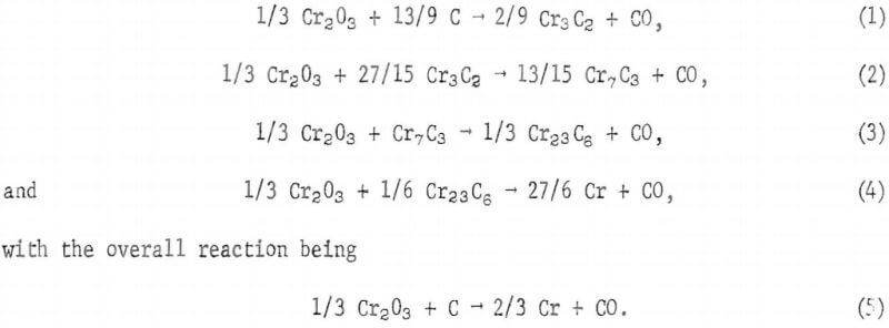
Boericke’s Cr4C compound has been more recently identified by Downing as Cr23C6.
He measured the equilibria in these reaction steps and derived thermo dynamic values for each reaction from equilibrium and requisite auxiliary thermal data.
Reactions 1 and 2 begin just below 1,300° C at atmospheric pressure; reactions 3 and 4 occur at much higher temperatures or require the removal of CO by either evacuation or dilution with inert gas flushing to proceed at 1,300° C.
Samarin and Vertman found the reduction rate of chromia to increase with increasing temperature in the range of 870° to 1,370° C. Soot was found to be a more effective reducing agent than graphite, and the rate of reduction at 1,300° C was found to increase with decreased pressure. Also, they found the rate of reduction to increase with decreasing grain size of the chromia.
The objective of the present investigation was to determine (1) the factors that influence the carbothermal reduction of chromite, (2) whether reduced products containing less than 2 weight-percent carbon could be obtained by this method, (3) what carbides are intermediate products in the reduction process, and (4) whether a ferrochromium alloy could be produced by simple melting of the reduced product.
Energy Considerations for Ferrochrome Alloy Production
Simplex Process
Production of LCFeCr by a vacuum reduction-melting process should have an advantage over production of LCFeCr by a submerged arc smelting-vacuum oxidation process (Simplex process). Private communications from industrial sources indicated that the energy expenditure for production of 1 long ton of high-carbon ferrochrome by three-phase submerged arc smelting in the Simplex process ranges from 4,500 to 6,400 kilowatt-hours, and an additional 4,000 to 6,000 kilowatt-hours is required in the process for the oxidation of a part of the HCFeCr and vacuum decarburization of the remaining HCFeCr with the oxidized HCFeCr to produce 1 long ton of LCFeCr. Thus according to these industrial sources, energy expenditure for production of 1 long ton of LCFeCr by the Simplex process ranges from 8,500 to 12,400 kilowatt-hours.
Although 2 tons of material must be heated in the vacuum furnace for each ton of ferrochrome alloy produced in the vacuum reduction-melting process, the energy expenditure with respect to the vacuum decarburization step in the Simplex process should be about the same; that is, 4,000 to 6,000 kilowatt-hours per long ton of LCFeCr produced since the furnacing time for the vacuum reduction is less than 50 percent of the furnacing time for the vacuum decarburization step in the Simplex process. Melting of the vacuum-reduced products of this investigation was estimated by the same industrial sources to require 900 to 1,200 kilowatt-hours per long ton of ferrochrome alloy produced. Thus, the total energy expenditure for production of 1 long ton of LCFeCr by the vacuum reduction-melting process is estimated to range from 4,900 to 7,200 kilowatt-hours. Comparison of these values with those for the Simplex process (8,500 to 12,400 kilowatt- hours) indicates a potential energy saving of 3,600 to 5,200 kilowatt-hours should be realized in the production of 1 long ton of LCFeCr by the vacuum-reduction melting process instead of by the Simplex process.
Alternatively, it appears that an additional energy savings of about 450 to 900 kilowatt-hours could be realized by adding the low-carbon-reduced products with the iron charge in the furnace to make stainless steel.
The iron charge would consist of a high scrap iron to pellet ratio in order to maintain a reasonable slag burden in the furnace. In this case, the furnace for melting the reduced products would not be required, and the gangue material in the reduced products would constitute much of the necessary slag burden in the furnace, and replace the part of the slag burden usually caused by the gangue in the pellets of the normal iron charge. The energy saved would be that necessary to heat and melt the gangue material in the reduced product melting furnace.
Perrin Process
Energy consumption for LCFeCr by the Perrin process is about 8,950 kilowatt-hours per long ton of LCFeCr. Comparison of this energy consumption with the estimated energy consumption of 4,900 to 7,200 kilowatt-hours per long ton of LCFeCr produced by the vacuum reduction-melting process indicates an energy saving of 1,750 to 4,050 kilowatt-hours should be realized in the production of 1 long ton of LCFeCr by the vacuum reduction-melting process instead of by the Perrin process.
Submerged-Arc Smelting and AOD Processes
Production of low-carbon stainless steels by addition of LCFeCr produced in the vacuum reduction-melting process should have an advantage over a process in which HCFeCr is produced in a submerged arc furnace, decarburized together with the iron charge in the AOD, and then added to the stainless steel bath to produce low-carbon stainless steels.
The estimated energy consumption of 4,900 to 7,200 kilowatt-hours for production of 1 long ton of LCFeCr by the vacuum reduction-melting process is comparable to the 5,400 to 6,300 kilowatt-hours required for production of 1 long ton of HCFeCr. (These estimates were obtained from industrial sources in a privated communication.) Thus, the energy savings between these two processes is the energy expenditure for decarburizing the high-carbon ferrochrome-scrap melt in the AOD. Production of low-carbon stainless steels by first producing a ferrochrome alloy with less than 2 percent carbon by vacuum reduction and simple melting, and then processing this alloy with scrap in the AOD should result in an energy savings equal to that required for decarburization of high-carbon ferrochrome to the carbon content of the vacuum reduction-melting process ferrochrome product.
Thermodynamic Analysis of Chromia-Carbon Reactions
Carbothermal reduction of the chromium in chromite (Fe3Mg)O·(Cr,Al)2O3 is complex, but guidelines for its reduction behavior can be obtained by investigating the carbothermal reduction of the constituent oxides, FeO, and Cr2O3. The free energy for the reduction of FeO by carbon to either iron or Fe3C is negative above 800° C, while the free energy for the reduction of Cr2O3 by carbon to carbide or metal is negative above 1,100° C. This means that the iron in the chromite should be reduced first, and the limiting reduction reactions should be those for the chromium in the chromite. Figure 1 gives the standard free energy change, AF°, for several reduction reactions of Cr2O3 as a function of temperature (lines A, B, and C). Superimposed on this diagram is a grid of dashed lines representing the quantity, RT Pco, as a function of temperature for CO partial pressures of 1, 0.1, 0.01, 0.001, and 0.0001 atmospheres. At equilibrium, AF° = -RT 2n PCo, thus the intersection of a solid line with a dashed line gives the equilibrium temperature for that reaction at the pressure represented by the dashed line.
It can be seen in figure 1 why reduction of Cr2O3 to Cr7C3 (line C), is more likely to occur than the reduction of Cr2O3 to chromium metal (line B). At any temperature, the reaction
1/3 Cr2O3 + 9/7 C → 2/21 Cr7C3 + CO…………………………(6)
is favored over the reaction
1/3 Cr2O3 + C → 2/3 Cr + CO………………………….(5)
by about 5 kilocalories per mole of CO formed, thus carbide formation is more likely than direct reduction to chromium metal.
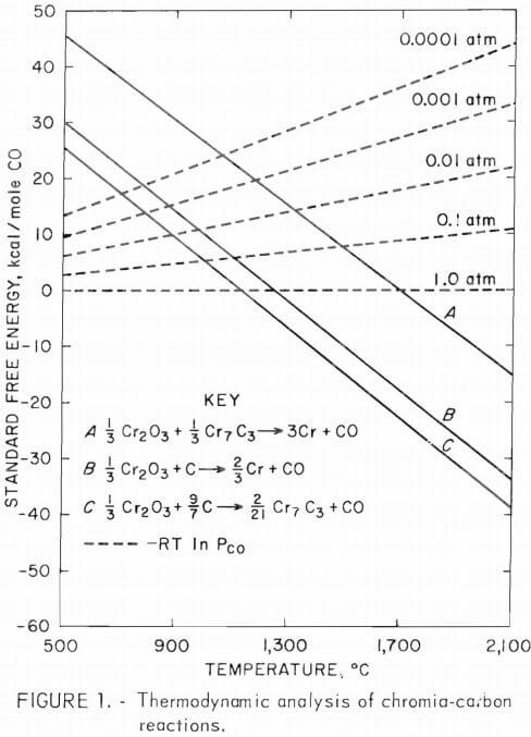 Line A represents the standard free energy change for the reaction
1/3 Cr2O3 + 1/3 Cr7C3 → 3Cr + CO…………………………(7)
and shows why the reduction will have to be carried out at reduced CO pressure in order to obtain chromium metal at a temperature below 1,700° C. Reduced CO pressure can be attained by flushing with inert gas or by evacuation as in the present investigation.
Materials
A minus 20-, plus 40-mesh table concentrate containing, in weight-percent, 9.6 Fe, 41.4 Cr, 2.7 SiO2, 15 6 MgO, 7.3 Al2O3 and 1.2 CaO was employed in this investigation. The Cr/Fe ratio for this concentrate is 4.31. The chromium-bearing mineral in the concentrate was chromite (Fe ,Mg)O·(Cr,Al)2O3, the principal gangue mineral was serpentine with some carbonate present. Reductants employed in this investigation were graphite, carbon black, foundry coke, and anthracite. The foundry coke and anthracite contained about 92.5 and 77.0 percent fixed carbon, respectively; the graphite and carbon black were essentially pure carbon.
Experimental Method And Apparatus
Carbothermal Reduction Studies
Concentrate and reductant materials were comminuted to the desired mesh sizes. Two-hundred-gram lots of concentrate were blended with 2 grams of chromium trioxide (CrO3) as a binder and the amount of carbonaceous reductant required for the reduction of Fe and Cr3+ in the concentrate and Cr6+ in the binder to metallics. The blended mixture was moistened to make a paste, pushed through a 14-mesh (Tyler) screen, and dried at 105° C. The spaghetti-like, dried product was broken and screened to give a porous minus 10- plus 20-mesh product. The undersize was repelletized.
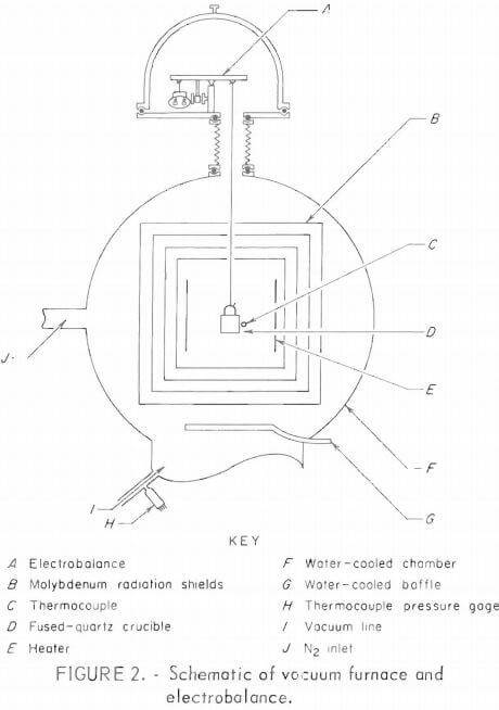 Figure 2 shows a schematic of the vacuum furnace and electrobalance. Samples of the pellets were put into the quartz crucible suspended from the electrobalance. The chamber was evacuated to less than 0.02 torr and backfilled with high-purity nitrogen to the desired pressure. The nitrogen was passed over hot copper turnings (480°C) to remove oxygen before entering the chamber. The sample was slowly heated with the tungsten heaters to the desired operating temperature, and the weight loss was continuously recorded on a strip-chart recorder. The temperature of the sample was monitored and controlled by a calibrated tungsten-rhenium thermocouple positioned near and behind the quartz crucible. This temperature was recorded on a second strip-chart recorder. Periodic checks of the temperature of the sample made with an optical pyrometer gave good agreement with the temperature determined by the thermocouple. The chamber pressure was monitored with the thermocouple pressure gage and controlled by adjusting a vacuum throttle valve.
The percent total reduction R(t) to iron and chromium metals at time t was calculated from the weight loss data by using the following relationship :
Rt = ∆W(t) – δ/∆W(∞) x 100………………………..(8)
where ∆W(t) is the observed weight loss of sample at time t
δ is weight loss due to volatile material,
and ∆W(∞) is the theoretical weight loss for total reduction of Fe2 +
and Cr3+ in the concentrate and Cr6+ in the binder to metallics.
A weight loss δ due to volatile material was obtained by heating the sample to 800° C; this weight loss was subtracted from ∆W(t). Except for the volatiles the sample did not lose any more weight until the temperature of the sample was between 1,080° C and 1,100° C, Zero time was taken at that time.
Polished sections of the reduced products were examined microscopically and analyzed on a microprobe. X-ray diffraction patterns and chemical analyses were made of reduced products in powdered form.
Melting of Reduced Products
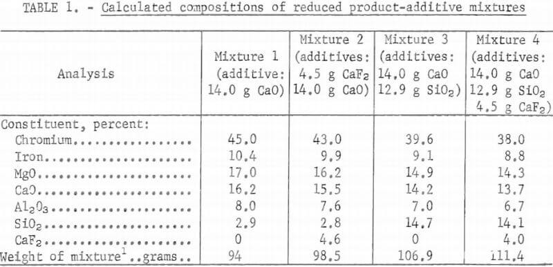
Twenty 25-gram samples of pellets of minus 400-mesh concentrate and minus 400-mesh graphite were heated to 1,300° C under 1 torr pressure. The reduction was allowed to proceed to near completion in each case. The reduced products from these tests were blended and split into four 80-gram samples, which were mixed with additives such as CaO, SiO2 and/or CaF2 and put in fused-alumina crucibles (3.5 centimeters ID by 9 centimeters long). The crucibles were placed in a second fused-alumina crucible (5.5 centimeters ID by 10 centimeters long) situated in the center of an induction furnace on a graphite pedestal and surrounded by graphite susceptors. The double-crucible configuration was heated to 1,700° C and soaked for 20 minutes. An optical pyrometer monitored the temperature of the melt. The sample was cooled to room temperature in the crucible, which was then cut in half to show the melted products. The quantity of major constituents in the mixtures were calculated from chemical analysis and weight loss data. These calculated percentages are listed in table 1.
Results and Discussion
Effect of Temperature on the Reduction
of Chromite Concentrate
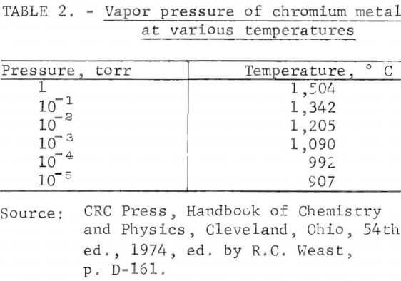
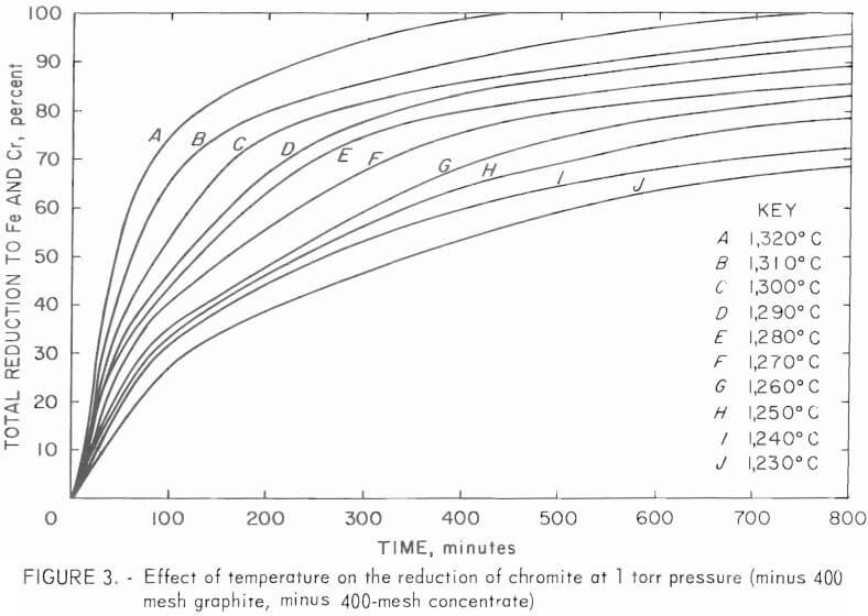
Twenty-five grams of pellets made from minus 400-mesh graphite and minus 400-mesh concentrate were heated to varying temperatures under 1 torr pressure. The carbothermal reduction of chromite at various temperatures in the range 1,230° to 1,320° C are shown in figure 3. Maximum temperature in each test was attained within 20 minutes. Figure 3 shows that the rate of reduction increases with temperature. It should be noted that there is a maximum temperature for reduction under a given pressure before the incipient vaporization of chromium. Table 2 shows vapor pressures of chromium metal at various temperatures. To prevent measurable chromium vaporization at a given temperature, the reduction should be carried out at a pressure that is at least 10 times greater than the vapor pressure of chromium at that temperature.
Effect of Pressure on the Reduction
of Chromite Concentrate
The carbothermal reduction of chromite, under pressures ranging from 0.1 to 1 torr are shown in figure 4. Twenty-five grams of pellets made from minus 400-mesh graphite and minus 400-mesh concentrate were heated to 1,300° C under pressures of 0.1, 0.4, 0.6, 0.8, and 1 torr. Figure 4 shows that larger degrees of reduction are achieved by decreasing the pressure. For any given temperature of operation there is a minimum pressure below which the metallic chromium begins to vaporize. This is illustrated by curve A surpassing 100-percent reduction because of additional weight loss due to chromium vaporization. Chemical analysis of the reduced product corraborated this observation. A material balance showed a loss of chromium in the reduced product. The different shape of curve A after 93-percent reduction is also probably a result cf chromium vaporization.
Effect of Reactivity of Carbonaceous Reductants
on the Reduction of Chromite Concentrate
Tests with four carbonaceous materials determined the effect of the reactivity of these reductants on the reduction of chromite. Twenty-five grams of pellets made from minus 400-mesh concentrate and a minus 400-mesh reductant were heated to 1,270° C under 1 torr pressure. Figure 5 shows
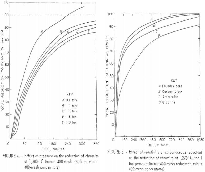
that in decreasing order of effectiveness, foundry coke, carbon black, and anthracite were all superior to graphite as reductants in the carbothermal reduction of chromite.
Effect of Particle Size of Reactants
on the Reduction of Chromite Concentrate
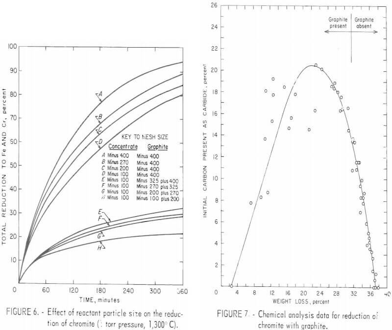
A series of 6-hour tests determined the effect of reductant and concentrate particle size on the reduction of chromite. Ten grams of pellets made of minus 100-mesh concentrate with minus 100 plus 200-, minus 200 plus 270-, minus 270 plus 325-, and minus 325 plus 400-mesh graphite, and minus 400-mesh graphite with minus 100-, minus 200-, minus 270-, and minus 400-mesh concentrate were heated to 1,300° C under 1 torr pressure. The results of these tests plotted in figure 6, indicate that for a minus 100-mesh concentrate particle size the rate of reduction increases with decreasing graphite particle size. A further increase in the rate of reduction is obtained by decreasing the concentrate particle size to minus 400 mesh while keeping the graphite particle size at minus 400 mesh. The fastest reaction was obtained with pellets of minus 400-mesh concentrate and minus 400-mesh graphite. The large gap between curves D and E indicates that the rate of chromite reduction is greatly accelerated with very fine graphite particles. In the latter case, only graphite particles between minus 325 and plus 400 mesh were available as reductants; whereas, in the former case, only graphite particles smaller than minus 400 mesh were available as reductants.
Evidence of Carbide Intermediaries
in the Reduction of Chromite
Tests were conducted to determine whether the reduction of chromite, like the reduction of chromia, proceeds via the carbide intermediates Cr3C2, Cr7C3 and Cr23C6 (reactions 1 through 4). Ten grams of pellets from minus 400-mesh graphite and minus 400-mesh concentrate were heated to 1,300° C under 1 torr pressure. The reduction was allowed to proceed to various stages of completion.
These partially reduced products were chemically analyzed for chromium, graphitic carbon, and total carbon. Total carbon was determined by a standard combustion technique using an automatic, carbon-combustion analyzer. Determination of graphitic carbon involved reacting the reduced product with a mixture of acids overnight to dissolve everything but the graphitic carbon. The resulting solution was filtered, and the residue analyzed for carbon by the standard combustion technique. The amount of carbidic carbon in the reduced products was determined from the difference between total carbon and graphitic carbon analyses.
Figure 7 shows the percentage of the carbon in the initial (unreduced) sample present as carbide in the partially reduced products versus percent weight loss for these partially reduced products. This curve shows the presence of carbides in all the reduced products, and thus supports the reduction of chromium in chromite via carbide intermediates.
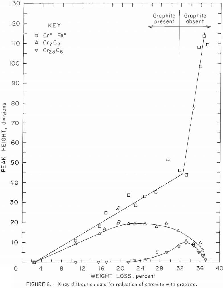
X-ray diffraction patterns were also made for partially reduced products. Peak height data from these X-ray diffraction patterns for Cr7C3. Cr23C6, and iron and chromium metallics are graphically shown in curves A, B, and C, respectively, of figure 8 as functions of percent weight loss of the sample. Peak heights for graphite and chromite peaks decreased with increased weight loss. Diffraction peaks for Fe3C and Cr3C2 were not observed in any of the diffraction patterns. Although peak height data are not quantitative, they do support the following reactions occurring consecutively as the chromite is reduced:
1/3 Cr2O3 + 9/7 C → 2/21 Cr7C3 + CO,………………………………….(9)
1/3 Cr2O3 + Cr7C3 → 1/3 Cr23C6 + CO,…………………………………(3)
and 1/3 Cr2O3 + 1/6 Cr23C6 → 9/2 Cr + CO…………………………..(4)
The reaction shown in equation 9 is supported by the decrease in peak heights for graphite and chromite and the increase in peak height for Cr7C3 up to about 23 percent weight loss (curve B). The decrease in Cr7C3 peak height (curve B) with the appearance of Cr23C6 peaks (curve C) at about 23 percent weight loss and the subsequent increase in Cr23C6 peak height (curve C) and continued decrease in Cr7C3 peak heights (curve B) with increased weight loss supports reaction 3. The initial decrease in Cr23C6 peak height (curve C) and drastic change in peak height for iron and chromium metallics (curve A) at about 33 percent weight loss and subsequent increase in the peak height for iron and chromium metallics with continued decrease Cr23C6 peak height supports reaction 4. The absence of graphite after about 31.5 percent weight loss indicates additional weight loss is due to reactions 3 and 4.
The reduction of iron from chromite would be expected to occur first and proceed simultaneously as follows since the free energies for these reactions are more negative than the chromium reduction reactions and are almost identical in value.
FeO + C → Fe + CO,……………………………………………(10)
and 3FeO + 2C → Fe3C + CO………………………………(11)
As the temperature is raised above 1,152° C, the reduced iron would most likely be in the liquid state since there is an eutectic composition of iron-carbon alloys containing 4.3 percent carbon, which is liquid above 1,152° C.
Thus, as Urquhart suggests in his review article on production of HCFeCr in a submerged-arc furnace, the reduction of chromium from chromite may proceed by the following reaction:
Cr2O3 (s) + 3C (s) → 2[Cr]Fe-o(l) + 3 CO (g)………………………………..(12)
where [Cr]Fe-o(l) represents chromium dissolved in the liquid iron-carbon alloy. Furthermore, since it is known that the presence of chromium reduces the activity of carbon in liquid iron melts, mixed carbides may precipitate from the melt [Cr]Fe-o(l) either at the temperatures of the experiments or upon cooling down to room temperature.
Microprobe analysis of a metallic-like phase of a reduced product (19.7 percent weight loss) showed that this phase contained Cr and Fe in a ration of 2.5:1 with about 9 percent of the phase composition not accounted for and presumably carbon. Al, Mg, Si, and Ca were absent from this metallic-like phase. It is concluded that a mixed carbide of the type (Cr,Fe)7C3 containing about 9 weight-percent carbon is one of the intermediates in the reduction of chromite. Microprobe analysis of the metallic-like phase of another reduced product (36.7 percent weight loss) showed that this phase contained Cr and Fe in a ratio of 2.8:1 with about 5.4 percent of the phase composition not accounted for and presumably carbon. Here again, Al, Mg, Si, and Ca were absent from this metallic-like phase. It is concluded that a mixed carbide of the type (Cr,Fe)23C6 containing about 5 to 6 weight-percent carbon is another of the intermediates in the reduction of the chromite.
The presence of the mixed carbides (Fe,Cr)7C3 and (Fe,Cr)23C6 and absence of a mixed carbide (Fe,Cr)3C2 analogous to Cr3C2 in chromia reduction may be explained on the basis of miscibility of the carbides. Chromium carbide (Cr7C3) can dissolve iron to replace up to 55 percent of the chromium. The cubic carbide (Cr23C6) can accommodate substitution of up to 25 percent of the chromium by iron, whereas Cr3C2 can accommodate very little iron. If Cr3C2 is formed in the reduction of the Cr2O3 in chromite, it would probably immediately dissolve in the liquid iron-carbon alloy. Since the structure accommodates very little iron the subsequent precipitation of (Fe,Cr)3C2 is not possible.
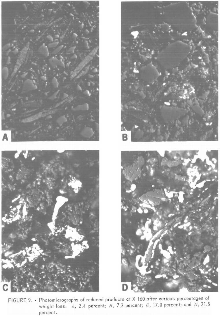
Figures 9 and 10 each show photomicrographs (X 160) of four partially reduced products. Figure 9A depicts a sample after the initial weight loss of 2.4 percent (below 800° C) but before any reduction has taken place.
The irregularly shaped grains are chromite and the cigar-shaped or elongated particles are graphite. No carbide or metallic phases are present. Figure 9B shows a sample after 7.3 percent weight loss. The reduction has begun, as evidenced by the appearance of fine particles of carbide phase (white). As the reduction continues (panels C and D), more carbide phase is present, and carbide particles are coalescing into larger rounded grains. Graphite and chromite grains are still present; however, a metallic-like phase is present in the cracks and holes that have appeared in the chromite grains. As the reduction proceeds further (fig. 10, panels A, B, and C), graphite is disappearing and is finally absent in the reduced product shown in 10C. The chromite grains have become more and more porous owing to loss of Fe and Cr. A metallic-like phase continues to be present in these defects. Carbide phases have coalesced into larger and larger particles. Some carbide particles contain both a high-relief and low-relief phase, which are differentiated because of dissimilar polishing hardness.
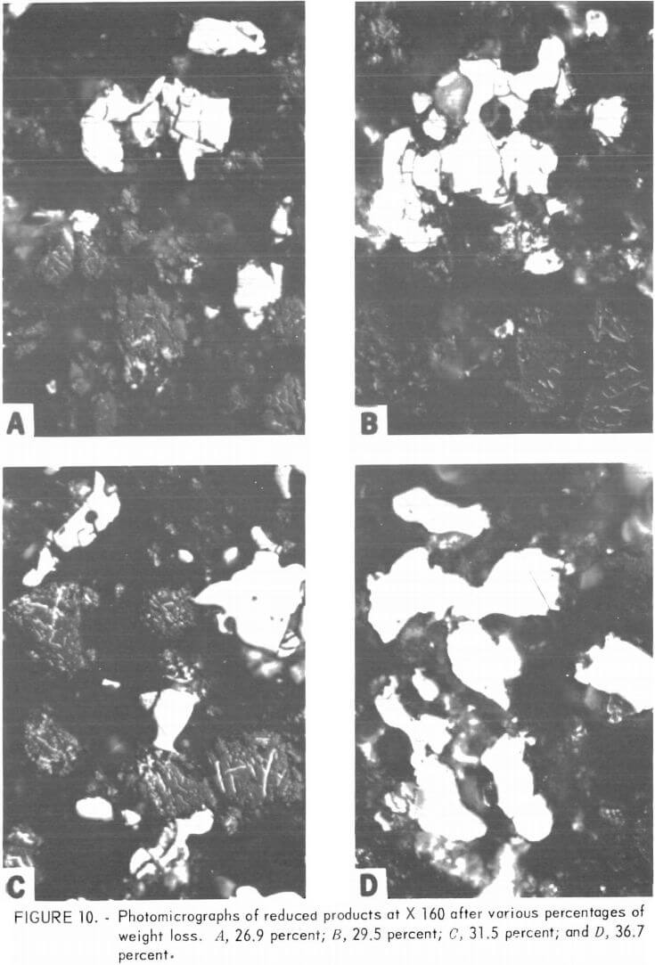
Explanation for this difference in hardness may be found in (1) differences in orientation of the same carbide phase, (2) difference in the iron and chromium ratio of adjacent grains of the same carbide phase, or (3) intergrowths of two different carbide phases As the reduction nears completion (fig. 10 D), the small carbide grains have coalesced into large particles that are lower in relief than the surrounding residual chromite particles or the carbide phases of reduced products that have undergone less reduction.
The coalescing of carbide particles into larger, well-rounded grains suggests that the carbide phase was at one time in the liquid state. This would tend to support the hypothesis that the reduction Cr2O3 in the chromite is done by carbon in the liquid iron-carbon alloy.
The low-relief metallic phase of the almost completely reduced products and several high-relief carbide phases of other partially reduced products were microscopically examined in more detail. Under polarized light, the carbide phases of the partially reduced phases were observed to be anisotropic (not cubic) in structure. Since iron-chromium alloys and (Fe,Cr)23C6 are cubic in structure and are isotropic in reflection under polarized light, it is probable that the carbide phase present in the partially reduced products is the tetragonal structure (Fe,Cr)7C3. The metallic phase in almost completely reduced products was much softer than the carbide phases of partially reduced products as evidenced by the low relief and fine scratch marks on the metallic phase in figure 10D. Also, this phase was isotropic under polarized light. It is believed that the metallic-like phase in almost completely reduced products is either the cubic carbide (Fe,Cr)23C6 or an iron-chromium alloy.
X-ray diffraction patterns for the partially reduced products showed that the major chromite peak broke into three distinct, closely related peaks for reduced products with about 20 or more percent weight loss. One of these peaks corresponded to the d-value of the main chromite peak, one corresponded to the MgAl2O4 spinel peak, and the third one could not be positively indentfied. For almost completely reduced products, the X-ray patterns showed the presence of MgO and the MgAl2O4 peak was the highest of the triplet peaks.
Total carbon analyses of graphite-reduced products indicated that a weight loss of about 33.8 percent was necessary to achieve reduced products containing 2 weight-percent carbon. A weight loss of about 35.8 percent was necessary to achieve reduced products containing 1 weight-percent carbon. Weight loss of about 36.8 percent was necessary to achieve reduced products containing less than 0.25 weight-percent carbon. Sixty reduced products containing less than 2 weight-percent carbon were obtained during this investigation; of these, 40 contained less than 1 weight-percent carbon, 20 contained less than 0.25 weight-percent carbon, 14 contained less than 0.1 weight-percent carbon, and 1 contained 0.01 weight-percent carbon.
Melting
Figure 11, panel A shows the cross section of mixture 1 (CaO addition) after soaking at 1,700° C for 20 minutes. A button of iron-chromium alloy had formed at the lower left of the crucible. However, many droplets of metallic phase were trapped in the slag phase, and thus indicating that complete segregation of the metallic and slag phases did not occur in the 20 minutes of soaking. It may be that complete segregation of the metallic and slag phases is possible if the soaking time at 1,700° C is in excess of 20 minutes. For the ore tested in this investigation, a weight of CaO equal to 17.5 percent of the weight of the reduced product to be melted was added. The quantity of CaO added to reduced products of other ores may vary depending upon their composition.
Figure 11B shows the cross section of mixture 3 (CaO and SiO2 addition) after soaking at 1,700° C for 20 minutes. The button of iron-chromium alloy formed at the bottom of the crucible shows that metallic and slag phases can be segregated by soaking a mixture of reduced products, CaO and SiO2 at 1,700° C for 20 minutes. For the ore tested in this investigation, weights of CaO and SiO2 equal to 17.5 and 16.1 percent, respectively, of the weight of reduced product to be melted were added to the reduced product. The quantity of CaO and SiO2 added to reduced products of other ores will vary depending upon their composition. In fact, it may be necessary to add CaO, SiO2 , MgO, and/or Al2O3 to attain a slag composition
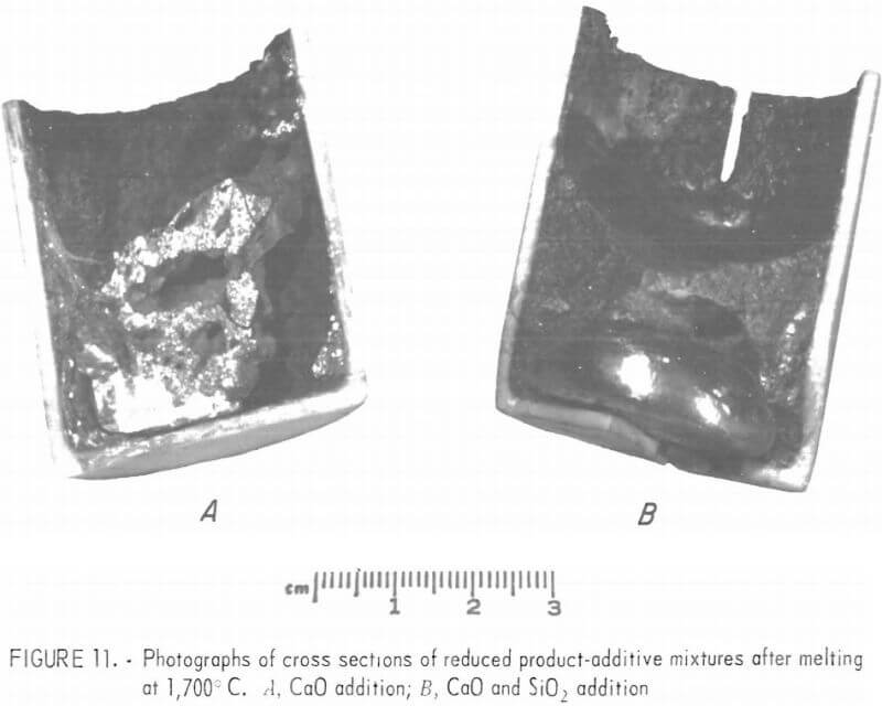
of 28 to 30 percent CaO, 28 to 30 percent MgO, 28 to 30 percent SiO2 , and 10 to 16 percent Al2O3,. As can be seen in figure 11B, a slag of this composition is fluid enough at 1,700° C to allow fast and complete segregation of the metallic and slag phases.
Soaking mixture 2 (CaO + CaF2 addition) at 1,700° C for 20 minutes resulted in only a few pinhead-size droplets of metallics in the slag phase. Soaking mixture 4 (CaO + SiO2 + CaF2 addition) at 1,700° C for 20 minutes yielded a button of metallics about one-sixth the size of that shown in 11B. It is concluded that addition of CaF2 to the reduced product does not improve the melting and segregation of the metallic and slag phases. Chemical analyses of the metallic buttons averaged 80.6 percent chromium, 18.6 percent iron, and about 0.8 percent carbon.
Summary and Conclusions
The reduction of chromite was found to proceed via the carbide intermediaries (Fe,Cr)7C3 and (Fe,Cr)23C6. Evidence of carbide intermediates analogous to Cr3C2 or Fe3C was not found. Reduced products containing less than 2 weight-percent carbon and as low as 0.01 weight-percent carbon were obtained by allowing the reduction to proceed to various stages of completion The extent of reduction increased with increased temperature and decreased pressure; however, operating conditions were limited due to the onset of appreciable chromium vaporization. The fastest reaction was obtained with pellets made with minus 400-mesh concentrate and minus 400-mesh reductant at 1,300° C under 1 torr pressure. Foundry coke, carbon black, and anthracite were found to be superior to graphite in the carbothermal reduction of chromite and are ranked in that order with respect to the speed of reduction. Buttons of ferrochrome alloys were made by melting a mixture of reduced products and appropriate amounts of CaO and SiO2 at 1,700° C for 20 minutes. Production of ferrochromium alloys by vacuum reduction and simple melting is technologically feasible. Whether it is feasible from an energy or economic standpoint requires a larger scale demonstration of the process.
Production of low-carbon stainless steels by first producing a ferrochrome alloy with less than 2 percent carbon by low-pressure reduction and melting, and then decarburizing this alloy with the iron charge in an AOD should result in an energy savings equal to that required for decarburization of the iron charge and HCFeCr to the carbon content of the iron charge and ferrochrome alloy produced by the low pressure reduction-melting method. Conservation of argon, chromium, ferrosilicon, and refractories are obvious advantages.
LCFeCr produced by the low-pressure reduction-melting method would eliminate the need for a submerged arc smelter and AOD since LCFeCr can be added with the iron charge directly to a melting furnace to make stainless steel. Capital savings would then be the difference in capital expenditure for a submerged arc furnace versus a vacuum furnace and melting furnace. The disadvantages of the AOD are eliminated and chromium is conserved.