Table of Contents
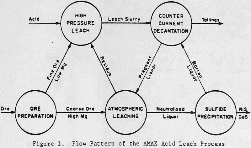
The AMAX sulfuric acid leaching process involves countercurrent digestion of nickeliferous laterite ore at high pressure and at atmospheric conditions. After solid/liquid separation, the nickel and cobalt values are precipitated by hydrogen-sulfide and refined into nickel and cobalt metal. Research at AMAX began in the early 1970’s at AMAX’s Extractive Research and Development Laboratory in Golden, Colorado, using as a model Cuba’s Moa Bay laterite acid pressure leaching operation. Substantial improvements were made over the Moa Bay process, particularly in the areas of metal recovery, energy consumption, and feed versatility.
One of the operating problems that must be addressed in design of the pressure leaching system is scaling of reactor surfaces. The formation of alunite and hematite deposits on the autoclave walls has been well documented by Russian authors describing the Moa Bay operation. Less recognized is the potential for formation of MgSO4·H2O and silica scale. These latter compounds can become troublesome when higher grade nickeliferous laterites containing greater amounts of magnesium silicate are treated.
Autoclaving of Laterite Ores High in Magnesium Silicates
The first commercial operation to utilize sulfuric acid pressure leaching to process nickeliferous laterite ore was Freeport Sulfur’s Moa Bay plant in Cuba. The Cuban government expropriated this plant in 1960 shortly after startup. The ore contained about 48% Fe, 5% Al, 4% SiO2, 1.4% Ni, and less than 1% Mg. It was wet screened at 20 mesh, thickened to 45% solids, and pressure leached in pachucas at 240 to 250°C with sulfuric acid. To attain 95% nickel extraction in 60 to 90 minutes, 0.22 pound of concentrated sulfuric acid per pound of ore was pumped into the first autoclave of a four autoclave train.
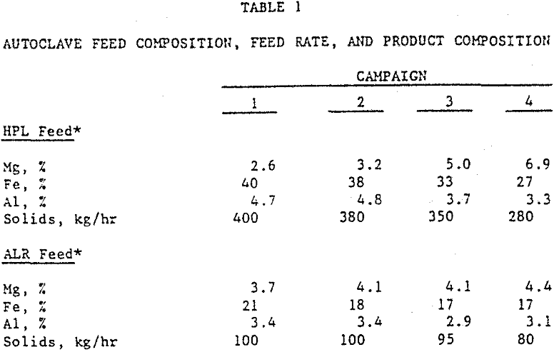
Prototype-plant demonstration runs were completed in 1980. Table 1 summarizes typical feed compositions, feed rates, and product compositions during four campaigns using various blends of New Caledonian limonite and garnierite ores. The duration of these campaigns ranged from 12 to 26 days. The HPL (high pressure leach) feed was pumped at 25 to 30 percent solids into the first autoclave compartment. This limonite fraction was over 90 percent minus 325 mesh, and consisted primarily of goethite (i.e., α-FeOOH). There was also 3 to 5 percent aluminum, mainly as gibbsite (i.e., α-Al(OH)3. Magnesium was present primarily as magnesium-iron silicates, although there was also some chromium spinel.
Characterization of the Magnesium Sulfate Scale
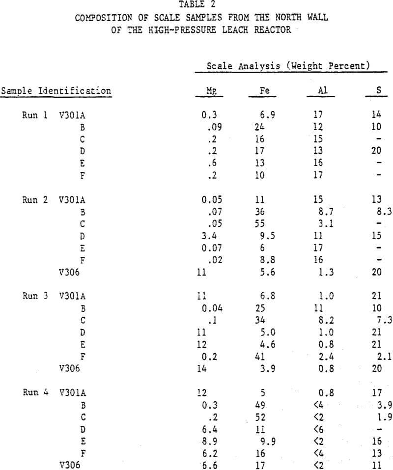
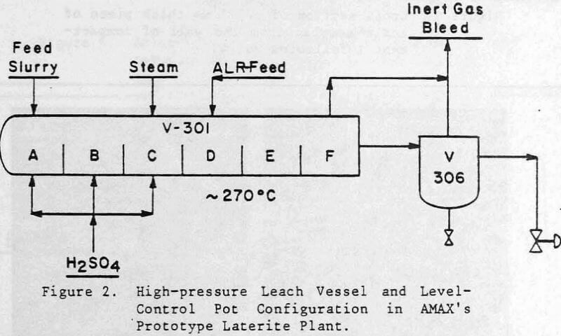
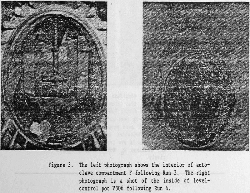
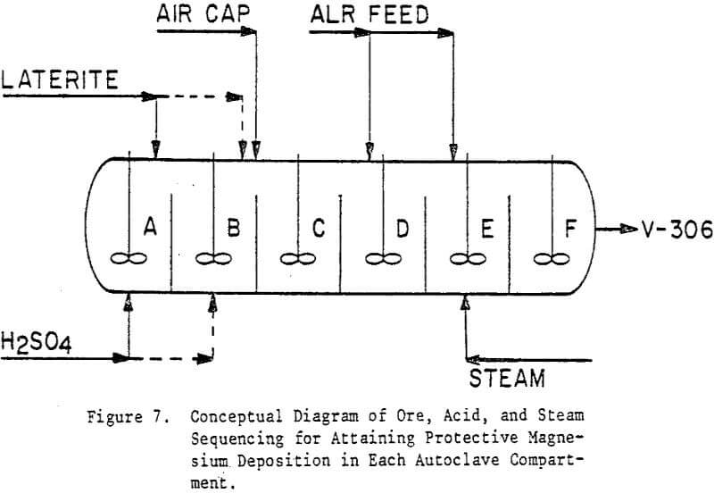
Magnesium sulfate deposits were found in autoclave compartments A through F, and in the level-control pot V306 located immediately upstream from the first pressure letdown choke. (Refer to Figure 2.) The deposits were reddish brown (no change in color on drying) and fine grained. X-ray diffraction showed that the magnesium compounds were Mg(Ni)SO4·6H2O and Mg(Ni)SO4·H2O. The Mg:Ni ratio ranged from about 1:1 to 3:1, roughly corresponding to the ratio of the Mg to Ni concentration in the aqueous solution from which the scale deposited. The distribution of concentrated H2SO4 fed into the first three compartments of the autoclave was 60%, 25%, and 15%. The addition point for the atmospheric leach residue (ALR) was into compartment E for Run 1, and into compartment D for subsequent runs.
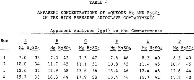
Table 4 summarizes magnesium and free acid concentrations as averaged during each campaign for each of the six autoclave compartments. Care must be exercised in utilizing these numbers, in that only the H2SO4 assays can be taken at face value, assuming one ignores the HSO4- shift reaction. The magnesium determinations represent not only the aqueous Mg soluble at temperature, but also the often large quantity of Mg that dissolved from the residue as magnesium sulfate when the sample was cooled below 200°C.
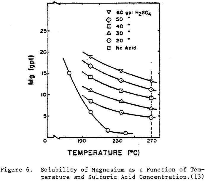
Magnesium Sulfate Solubility Relationships
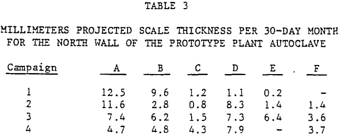
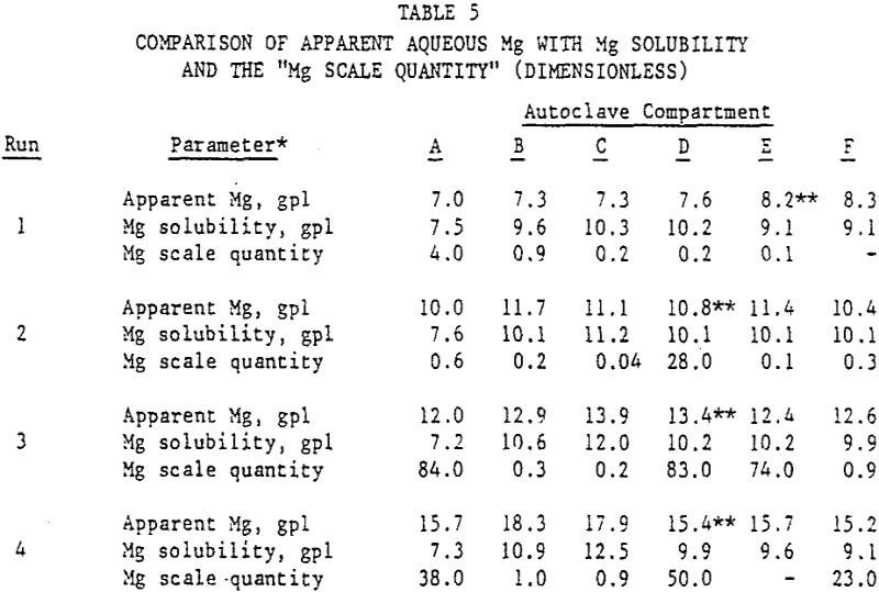
A comparison of the concentration of aqueous magnesium at room temperature (in slurry samples collected from the 270°C prototype autoclave) was made with W. Marshall solubility values. This comparison appears in Table 5. Also shown is the “Mg scale quantity number” obtained by multiplying the measured scale thickness in mm (Table 3) by the magnesium analysis of the scale (Table 2). For Run 1, the solution concentration in all six compartments never exceeded the solubility of magnesium. Refer to Table 5. Therefore, there was very little magnesium sulfate scaling in the prototype plant autoclave during this run.
One would have also expected to find more scale after Run 4 than 3, based on apparent leach liquor magnesium concentrations. The lower measured scale thickness following Run 4 probably was due to the autoclave being washed particularly thoroughly with water during the shutdown procedure that followed this high-magnesium campaign. Thus, residual magnesium scale was greater following Run 3 than following Run 4 due to the difference in flushout procedures.
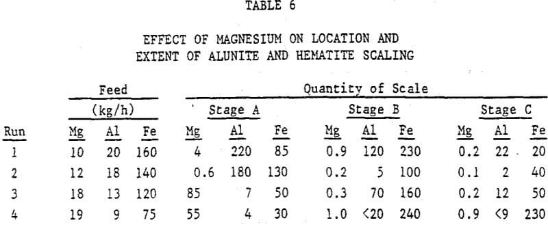
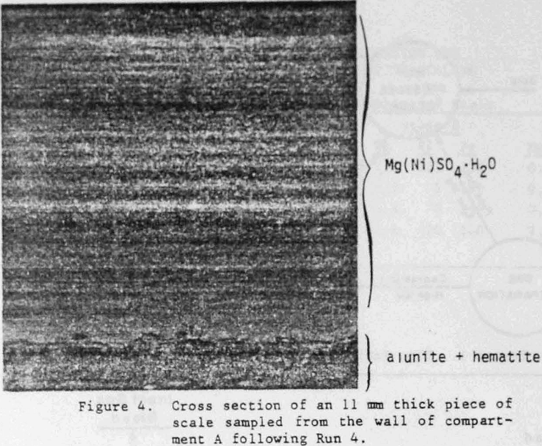
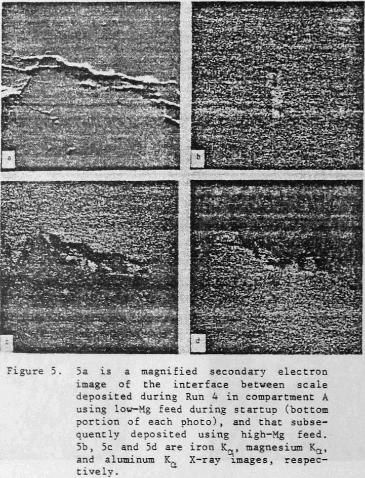
Effect of Magnesium Sulfate Deposition on Alunite and Hematite Scale Formation
The photographs shown in Figures 4 and 5 are striking evidence of the change in scale morphology that can result from the presence of MgSO4·H2O. During Run 1, the solubility of magnesium was not exceeded in autoclave compartment A. See Table 5. The scale deposited in compartment A was composed of refractory intergrown crystals of alunite and hematite (Figure 5 and Table 2). When the autoclave feed was changed over to high-magnesium material (Run 4; Table 1), deposition of alunite essentially ceased (Figure 5). The scale deposit became MgSO4·H2O containing a fine dispersion of iron plus traces of aluminum.