Plants which process materials in the form of bulk solids have not been able to use control to as great an extent, primarily due to the lack of measuring equipment capable of providing the same types of continuous automatic control available with liquid flow meters.
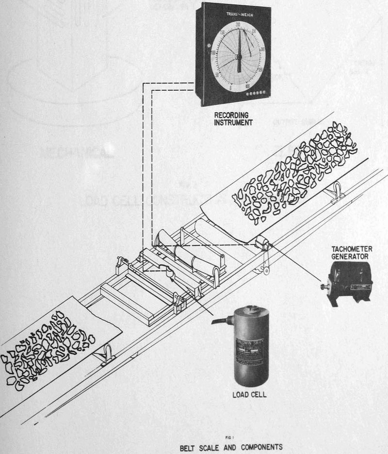
A conveyor belt idler is supported on a rigid carriage which in turn is mounted in two anti-friction bearings on the conveyor stringers. The pivoted carriage is prevented from rotating about the pivot shaft by an electric strain gauge load cell connected between the carriage and a cross support. Increasing load on the conveyor belt increases the moment of the carriage frame about the pivot shaft, and proportionally increases the tension in the load cell. The belt speed is measured by a conventional d. c. tachometer generator driven from a pulley, usually on the return belt.
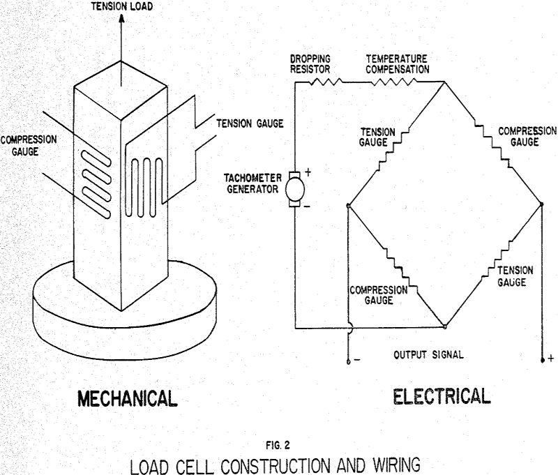
For measuring weight only, as in a conventional platform scale application, the load cell power supply would be a constant voltage. The output voltage from the strain gauge would then be proportional to the load on the cell only.
Most automatic control applications of conveyor scales simply provide for control of the feed rate at a desired value set by the operator. However, a growing number of processes require that several materials be controlled in proportion to each other, and the remainder of this paper will describe some systems of that type.
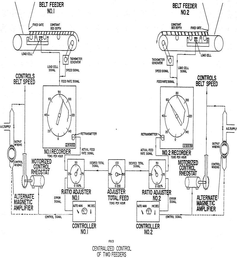
Instruments showing the feed rates are located at an operator’s station wherever most convenient. One total adjustment is provided, calibrated in tons per hour or pounds per minute, so the operator may set the sum of both feeders. Signals proportional to this desired total feed rate go to the ratio adjusters for each material. Each ratio adjuster has a calibrated dial reading in per cent of the particular material. The circuit of the ratio adjuster computes the desired value for the particular material by multiplying the desired total feed rate times the percentage setting.
Alternatively, most electric variable speed feeders and vibrating feeders can be controlled by magnetic amplifiers instead of motorized rheostats, in that case, the controller output signal would be a low-energy direct current to the control winding of a magnetic amplifier, and the output of the magnetic amplifier would supply a higher power a. c. or d. c. signal for operating the feeder.
The illustration shows belt feeders, where the material is drawn from a hopper through a gate so that a constant depth of bed occurs on the belt at all times, but the same control technique is applicable to other types of feeders.
The higher expanding secondary coal is brought in by barge and stored in ten bins having a total capacity of about 5, 000 tons. This capacity was chosen to allow two-shift operation of the preparation plant with one-shift unloading of the barges. Each bin has its own belt feeder with variable-speed control. The speeds of all the feeders are controlled together by one control rheostat, but up to five of the feeders may not be in use at any one time. A collection belt carries the secondary material from the belt feeders to an inclined conveyor at an average rate of about 600 tons per hour and the inclined conveyor carries the material up to join the primary stream. The mixture then goes to the preparation plant.
The primary flow is measured by a belt scale located part way across the bridge, and the secondary flow is measured by a belt scale located just after the loading point on the inclined conveyor. The location of the primary scale is chosen to make the time lags equal between each scale and the junction point. That is, when a change passes over the primary scale, the control immediately produces a proportional change in the secondary feed rate and the two changes meet at the junction point at about the same time.
This plant had no trained instrument maintenance people at the time of installation of this equipment, but one man with radio and T. V. experience was assigned to maintenance on this and other instrumentation in the plant.
Many other different types of automatic control applications could be described in a longer paper. One type of particular interest is “cascade” control, where the control point of a scale is set automatically by some other process variable. For example, in a closed circuit grinding system, a measurement of the recirculating load may be used to reset the control point of a scale feeding the mill, so that changes in grindability of the material will automatically cause changes in the input feed rate to keep the recirculating load at the value corresponding to best mill operation. Similarly, the feed of material to kilns may be set automatically by temperature measurements, etc.
The major potential advantages obtainable in the use of such automatic control equipment are uniformity of product through controlled feed rates, and increased production by being able to operate process equipment right up at capacity. Controlled conditions often allow adjustment of other process equipment and machinery at their most efficient points whereas it would be impossible to establish such adjustments with the feed rates continually varying. Often operating costs can be reduced by having centralized instrumentation but sometimes these savings are balanced out by increased maintenance costs. The maintenance problems are the same type as encountered in other common control problems such as temperature, pressure, liquid flow, etc.
It will be obvious from the foregoing that many plant design problems enter into the automatic control picture. It is no secret that a successful installation involves more than just buying a controller, and that the control problems should be considered in the plant design stage whenever possible. Without going into great detail, the following general comments are intended to cover some important design factors.
The physical spacing of feeders and scales affects questions involving time lags and may point toward more complicated controls such as the combination belt and feeder speed system described above, depending on the desired results. Control is always improved by decreasing the time lag between feeder and scale. Sometimes several feeders deliver material to one belt and in those cases it may be desirable to control only the closest feeder if the other feeders add considerable time delay.