
UNTIL THE THIRD THEORY OF COMMINUTION of “Work Index” method of determining crushing and grinding mill size was introduced, there was no way of accurately figuring the most applicable, most economical size of crushing and grinding mill.
Naturally, with little or no factual operating data correlated in useful form, it was easy enough, even for the most experienced, to arrive at an incorrect size of crusher or grinding mill, especially when a slightly smaller unit carried an advantage in initial investment.
The “Work Index” method, frequently referred to as the Bond* method, is based on extensive field operating data and equally extensive laboratory data covering wide varieties of materials, ranges of reduction sizes and types of equipment. The correlation of all this factual material enabled the establishment of a consistent common factor, known as the Work Index, for accurately determining crushing and grinding mill sizes.
The Work Index is actually the total work input in kwhr/short ton required to reduce from theoretically infinite particle size to 80% passing 100 microns, or to approximately 67% passing 200 mesh.
Knowing the Work Index, one has but to apply the proper given equation to determine the power input required. The calculated power input in turn enables you to select the proper crusher or grinding mill unit. Selection of various sizes of machines is made from the power requirements listed in equipment manufacturer’s published bulletins. The following example will help clarify the above procedure.
EXAMPLE CALCULATION:
Assume a capacity of 2000 short tons of average material per day. A Work Index of 13 over the entire size range. A feed 80% passing 3″ and a final desired product of 80% passing 100 mesh. These, then, work out as follows:
|
Operation Stage |
Crushing | Rod Milling |
Ball Milling |
| Circuit | Open-Dry | Open-Wet |
Closed-Wet |
|
Hours per Day………………………………………….. |
14 | 24 |
24 |
| Tons per Hour…………………………………………… |
143 |
83.4 |
83.4 |
| Feed: 80% size………………………………………….. |
3″ |
3/4″ |
14 mesh |
|
or Microns F……………………………………. |
76,200 |
19,050 |
1190 |
| Product: 80% size……………………………………… |
3/4″ |
14 mesh |
100 mesh |
|
or Microns P………………………………. |
19,050 |
1190 |
149 |
| Red. Ratio: Rr = F/P…………………………………… |
4.00 |
16.00 |
8.00 |
| Wi/W = 13.0/W………………………………………….. |
27.6 |
4.60 |
1.89 |
| Kwhr/Ton = W…………………………………………… |
0.471 |
2.83 |
6.88 |
| Hp or calculated power input =
W x TPH x 1.34……………………………………….. |
90.3 |
316 |
769 |
* Crushing provides for two 7-hour shifts, eighth and sixteenth hours are for cleanup. Rod and Ball Milling each provide for three 8-hour shifts of continuous operation.
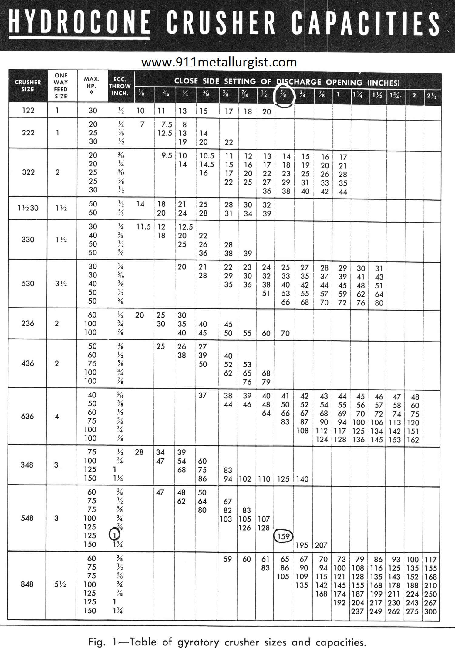
By referring to equipment manufacturer’s bulletin on crushers, Fig. 1, a crusher producing 80% passing 3/4″ requires a close side setting of approximately 5/8″. Since the selected crusher capacity must be in excess of 143 tons per hour, the next higher figure (159) is chosen. The 159 indicates a 548 crusher size with 1″ eccentric throw. With 1-in. eccentric throw, the motor hp allowed on the crusher is a maximum of 125. However, since only 90.3 hp is required for this average material, a 100-hp motor is sufficient.
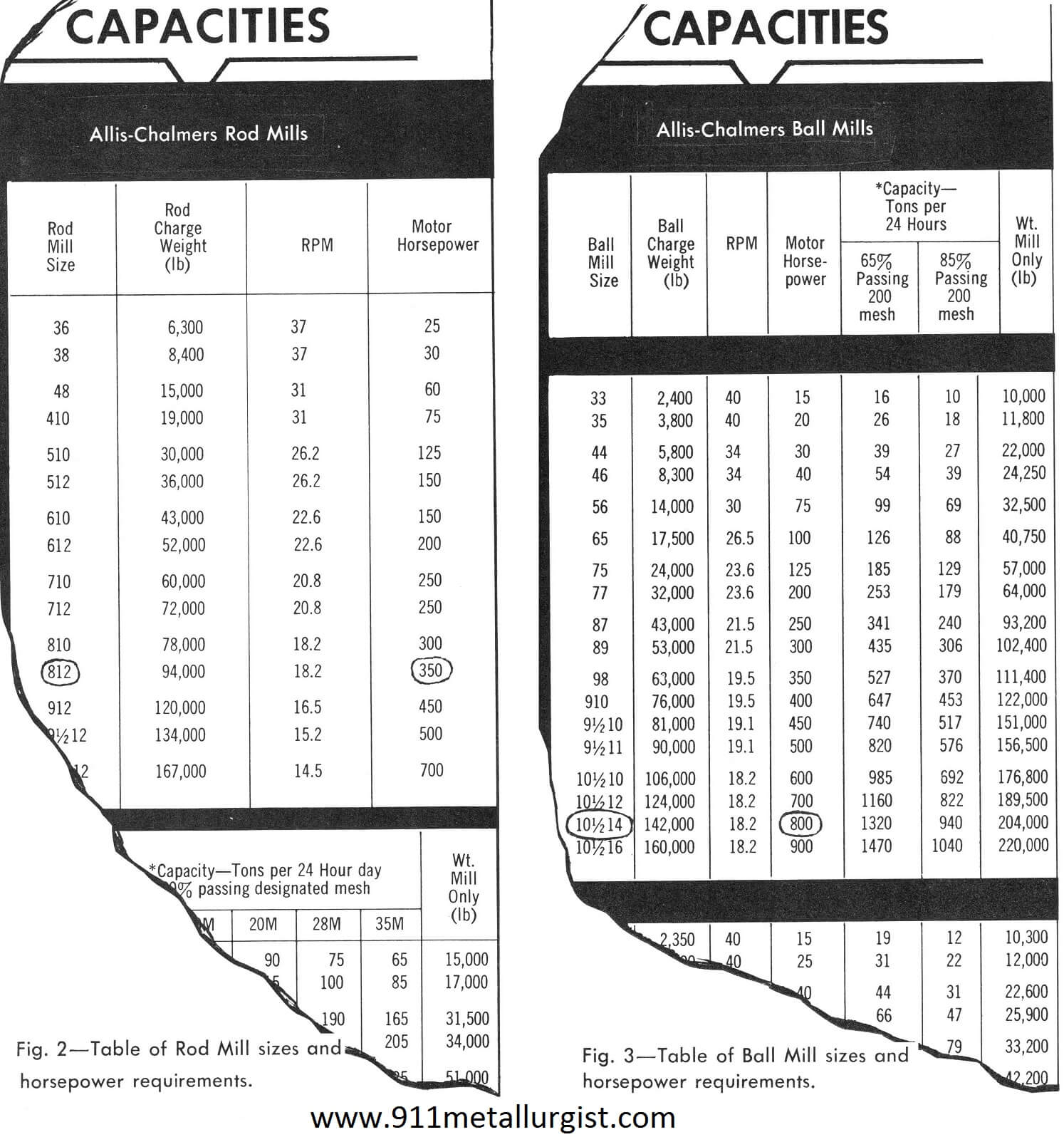
Fig. 2, taken from manufacturer’s bulletin, lists horsepower requirements and Rod Mill sizes. The calculated power input or horsepower in the above example is 316. Therefore, a 350-hp motor is required and this in turn indicates that an 812 (8′ x 12′) Rod Mill is required.
In the same way Fig. 3 indicates that an 800-hp motor and a 101/214 or 10.5′ by 14′ Ball Mill is required.
Following is a condensed tabulation of the above selections.
Sizing a Ball or Rod Mill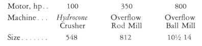
Sizing a Crusher using >1200 Wi of Ores from Database
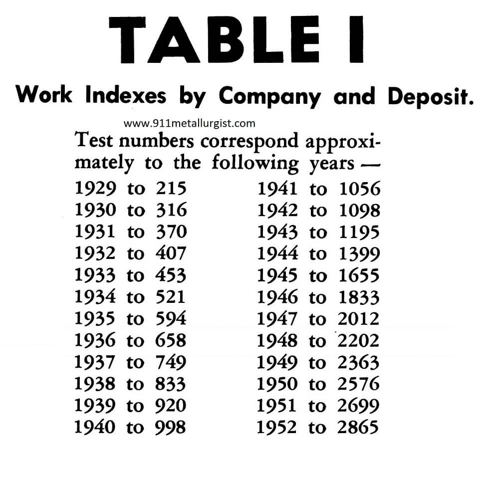
For your convenience, this manual lists over 1200 work indexes. Table I lists the Work Indexes alphabetically by company and deposit. Table II lists the Work Indexes alphabetically by materials. Table III lists the average Work Indexes alphabetically by different types of materials.
In the event these 1200 listings of Work Indexes do not include the particular one that applies to your particular material, you can readily determine it, since the Work Index expresses the resistance or a material to crushing and grinding and the relative efficiency of any machine.
How to Find the Work Index (Wi)
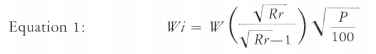
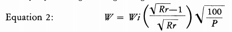
Let W represent the work input in Kwhr/T, F the feed size or diameter in microns of the square hole which 80% of the feed passes, P the product size or microns which 80% of the product passes, and Rr the reduction ratio F/P. To find the Work Index (IF/) use Equation 1.
How to Find the Work Input (W)
The following equation is used to find the work input (W) required to reduce from any feed size to any product size by dry crushing or wet grinding.
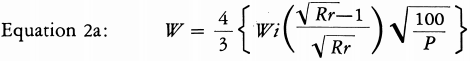
The work input (W) for dry grinding can be found by applying Equation 2a.
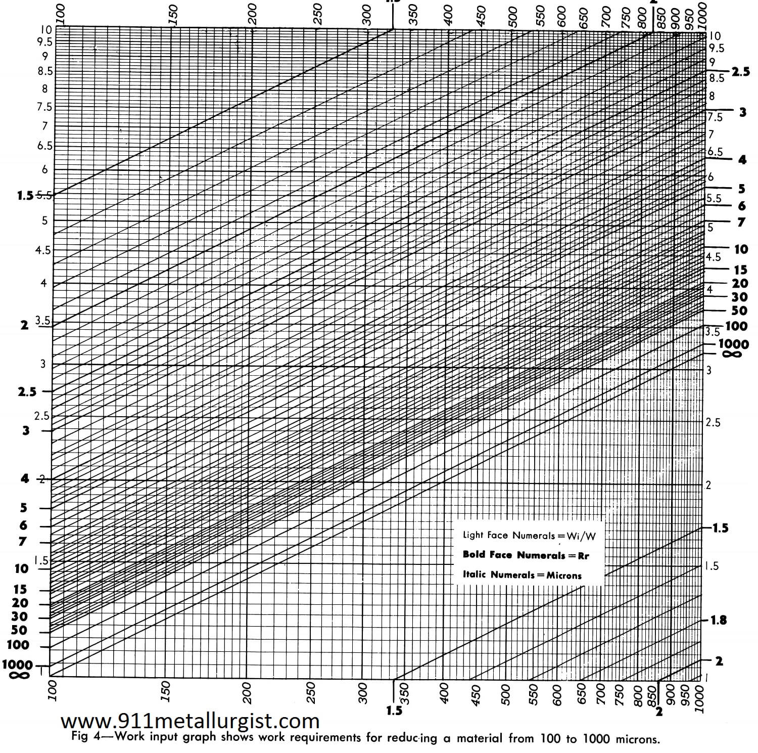
Equations 1, 2 and 2a may be solved graphically by plotting Wi/W against the product size (P) on log-log paper, as shown in Fig. 4.
Although the chart in Fig. 4 covers the range of product sizes from 100 to 1000 microns, it illustrates a practical method of developing charts to cover any product size range.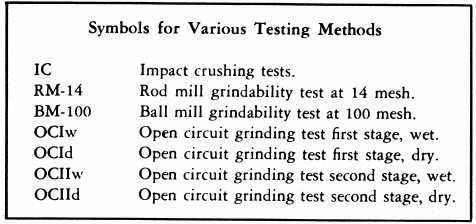
The 80% passing size in microns is a convenient term for expressing the fineness of a crushed or ground product. It is also a convenient base for calculating the reduction ratio and the work required for reduction. It is readily found by plotting the percent passing on log-log paper, as in Fig. 5, to determine the size distribution curve.
When the size distribution curves of the feed and product are parallel, the reduction ratio remains constant for all particle sizes, and the Work Index calculated from the 80% passing size is equivalent to that calculated on the basis of any other selected percent passing size.
Small differences between the slopes of the plotted feed and product lines have only a slight effect on the Work Index, proportional to the square root of the effect upon the surface areas. However, when the feed has had the fines removed the feed size is changed and the Work Index may be considerably in error. In cases where a crusher feed is scalped by passing over a grizzly screen, with openings equal to or smaller than the crusher openings, the tonnage and size distribution of the fines removed are rarely known. It is preferable, therefore, to consider the feed to the grizzly as being equivalent to the feed to the crusher and calculate the Work Index on this basis.
How to Correct Calculated Work Indexes for Unnatural Feeds
Several methods (2) have been used to correct the calculated Work Index for large differences between the product and feed slopes, when plotted as in Fig. 5. A newer method is the use of the average reduction ratio Rra. This can be obtained by averaging the reduction ratios at 90, 70, 50, 30 and 10% passing. The reduction ratio, at any percent passing, can be obtained quickly. Place a piece of the log- log paper (the same as used in plotting) along the percent passing line as indicated by the dotted lines A and B, Fig. 5. With point A coinciding with 100 on the micron scale and B coinciding with 773 on the same scale, 7.73 is the reduction ratio at that percent passing.
The Work Index values listed in Table I and II apply directly to a wet grinding overflow type rod mill 7.5 feet in diameter in open circuit; and to a wet grinding overflow type ball mill 7.5 feet in diameter in closed circuit with a rake classifier at 250% circulating load, and with 80% or more of the feed passing 4 mesh. Correction factors should be applied for over-size feed and other operating conditions which change the grinding efficiency. When Work Index values at several different product sizes are available (see Tables I and II), the value nearest the actual product size should be used. The Work Index represents the total work input necessary in installations of average efficiency.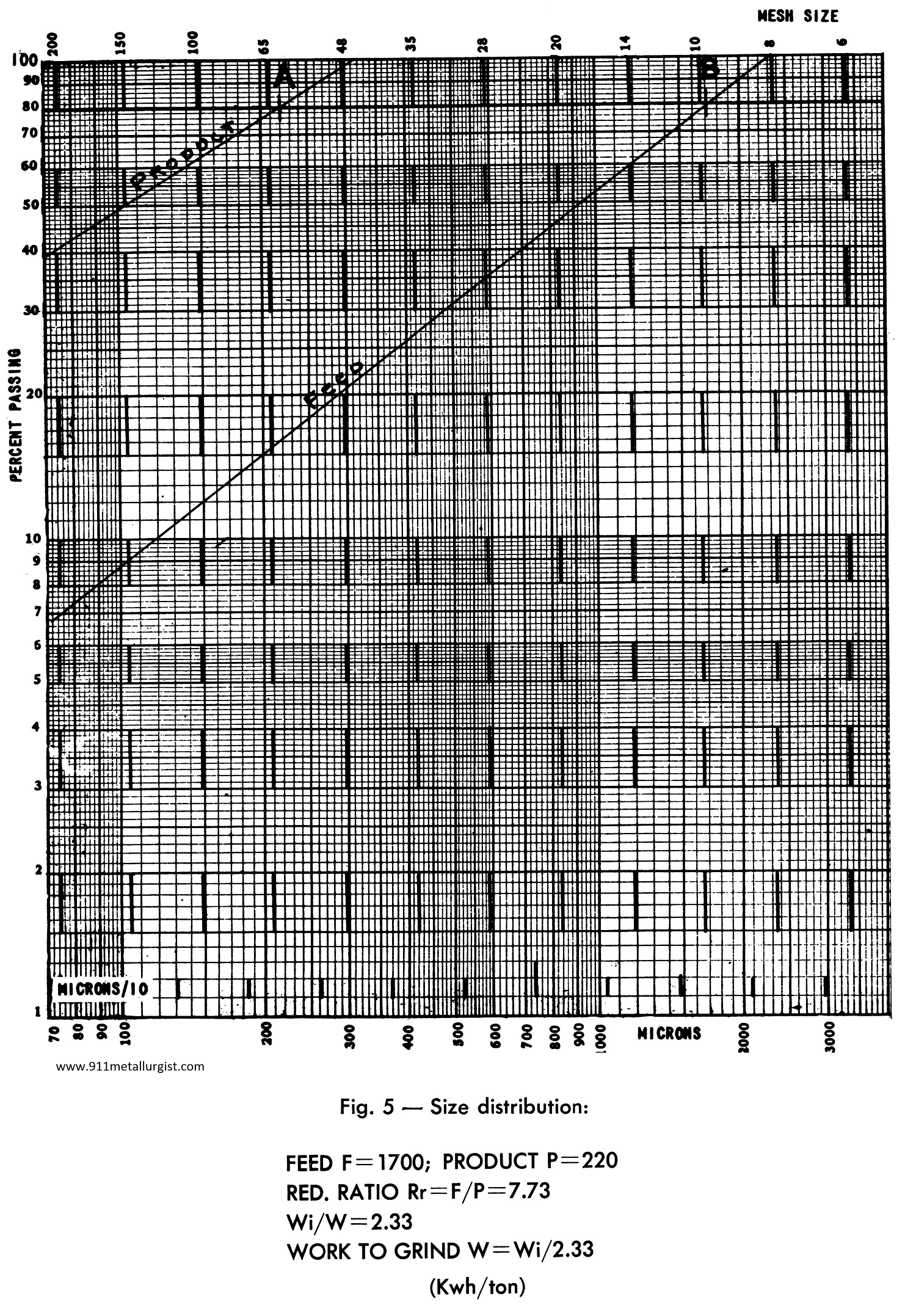 How to Find Work Index From Impact Crushing Tests
Where C represents the impact crushing strength (1) in foot-pounds per inch of thickness and S is the specific gravity, the Work Index is found by Equation 3.
Equation 3: Wi = 2.59 C/S
How to Find Impact Crushing Strength From the Work Index
The impact crushing strength (C) is found from the listed Work Index by Equation 4.
Equation 4: C = Wi S/2.59
How to Find Work Index From Closed Circuit Grindability Tests
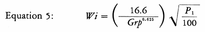
Where Grp represents the rod mill grindability (1) in net grams produced per revolution of the test mill which passes a sieve opening of Pi microns, the Work Index is found from equation 5.
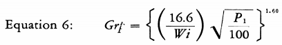
The rod mill grindability is found from the listed Work Index by Equation 6.
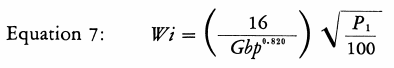
Where Gbp represents the ball mill grindability (1) at Pi microns, the Work Index is found from Equation 7.
The ball mill grindability is found from the listed Work Index by Equation 8.
The Work Index is found from the first stage of the wet open circuit grinding tests (1) by multiplying the grinding index Iw by 0.0082, and from the first stage of the dry open circuit grinding tests by multiplying the dry grinding index Id by 0.00546.
How to Find Work Index From Open Circuit Grindability Tests
The Work Index is found from the second stage of the wet open circuit grinding tests(1) by multiplying the grinding index IIw by 0.0022, and from the second stage of the dry open circuit grinding tests by multiplying the dry grinding index IId by 0.00147. The second stage dry open circuit grinding tests may show an increased Work Index because of ball coating, and are not reliable if ball coating exists.
Use of the Work Index
The Work Index can be calculated by Equation 1 from commercial crushing or grinding data or from pilot mill tests, and compared with the listed Work Indexes in Tables I and II to obtain the relative mechanical efficiency.
The capacity of any size reduction machine over its normal range of feed and product sizes is proportional to
In cases where the capacity is found to vary more than this amount, some condition causing inefficient operation should be suspected. These may include packing in a crusher, oversize feed or improper ball and rod sizes in a tumbling mill, and coating dry in grinding.
Laboratory Tests for Determining Work Indexes
Impact crushing tests, as well as rod mill and ball mill grindability tests, can be made at cost by the www.911metallurgist.com Laboratories. To run a proper test, a representative sample of 50 pounds minimum is required. The sample for an impact crushing test should be no finer than 2″. The sample for a rod mill grindability test should be no finer than 80% passing 0.5″, and the sample for a ball mill grindability test should be no finer than 80% passing 6 mesh.
REFERENCES
FRED C. BOND— Special Engineer with Allis-Chalmers Mfg. Co. “Standard Grindability Tests Tabulated,” Trans. AIME (1949) vol. 183, page 313, TP 2180, Mining Technology, July 1947.
FRED C. BOND—”The Third Theory of Comminution,” Trans. AIME, TP 3308B, Mining Engineering, May 1952.
Work Index Table I
Work Index Table II
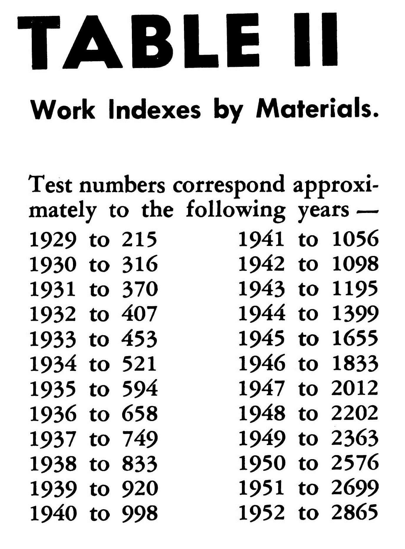
TABLE III
Wi BY MINERAL/MATERIAL Table III
|
SPECIFIC |
WORK |
||
|
NO. OF |
GRAVITY |
INDEX |
|
|
MATERIAL – Ore Types |
TESTS | “S” |
”Wi” |
| All Materials Tested | 1242 | —– | 14.39 |
| Andesite | 6 | 2.84 | 18.25 |
| Barite | 7 | 4.50 | 4.73 |
| Basalt | 3 | 2.91 | 17.10 |
| Bauxite | 4 | 2.20 | 8.78 |
| Cement clinker | 16 | 3.15 | 13.45 |
| Cement raw material | 19 | 2.67 | 10.51 |
| Clay | 7 | 2.51 | 6.30 |
| Coal | 2 | 1.4 | 13.00 |
| Coke | 8 | 1.31 | 15.13 |
| Copper ore | 204 | 3.02 | 12.73 |
| Diorite | 4 | 2.82 | 20.90 |
| Dolomite | 5 | 2.74 | 11.27 |
| Emery | 4 | 3.48 | 56.70 |
| Feldspar | 8 | 2.59 | 10.80 |
| F erro-chtome | 9 | 6.66 | 7.64 |
| F erro-manganese | 5 | 6.32 | 8.30 |
| F erro-silicon | 13 | 4.41 | 10.01 |
| Flint | 5 | 2.65 | 26.16 |
| Fluorspar | 5 | 3.01 | 8.91 |
| Gabbro | 4 | 2.83 | 18.45 |
| Glass | 4 | 2.58 | 12.31 |
| Gneiss | 3 | 2.71 | 20.13 |
| Gold ore | 197 | 2.81 | 14.93 |
| Granite | 37 | 2.66 | 15.13 |
| Graphite | 6 | 1.75 | 43.56 |
| Gravel | 15 | 2.66 | 16.06 |
| Gypsum rock | 4 | 2.69 | 6.73 |
| Iron ore | |||
| Hematite | 61 | 3.53 | 12.84 |
| Hematite — specular | 3 | 3.28 | 13.84 |
| Oolitic | 6 | 3.52 | 11.33 |
| Magnetite | 58 | 3.88 | 9.97 |
| Taconite | 56 | 3.54 | 14.61 |
| Lead ore | 10 | 3.35 | 11.90 |
| Lead-zinc ore | 16 | 3.36 | 10.93 |
| Limestone | 79 | 2.66 | 12.74 |
| Manganese ore | 12 | 3.53 | 12.20 |
| Magnesite | 9 | 3.06 | 11.13 |
| Molybdenum | 6 | 2.70 | 12.80 |
| Nickel ore | 8 | 3.28 | 13.65 |
| Oil shale | 9 | 1.84 | 15.84 |
| Phosphate rock | 17 | 2.74 | 9.92 |
| Potash ore | 8 | 2.40 | 8.05 |
| Pyrite ore | 6 | 4.06 | 8.93 |
| Pyrrhotite ore | 3 | 4.04 | 9.57 |
| Quartzite | 8 | 2.68 | 9.58 |
| Quartz | 13 | 2.65 | 13.57 |
| Rutile ore | 4 | 2.80 | 12.68 |
| Shale | 9 | 2.63 | 15.87 |
| Silica sand | 5 | 2.67 | 14.10 |
| Silicon carbide | 3 | 2.75 | 25.87 |
| Slag | 14 | 2.74 | 10.24 |
| Slate | 2 | 2.57 | 14.30 |
| Sodium silicate | 3 | 2.10 | 13.50 |
| Spodumene ore | 3 | 2.79 | 10.37 |
| Syenite | 3 | 2.73 | 13.13 |
| Tin ore | 8 | 3.95 | 10.90 |
| Titanium ore | 14 | 4.01 | 12.33 |
| Trap rock | 17 | 2.87 | 19.32 |
| Zinc ore | 12 | 3.64 | 11.56 |
A reproduction of a 1953 Allis-Chalmers pamphlet.