Table of Contents
Mechanical Development – Laboratory Testwork
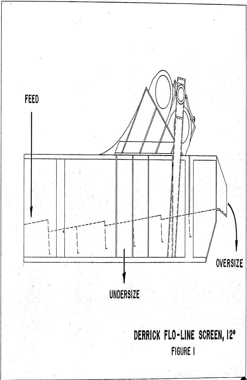
Derrick Manufacturing Corporation originally developed the 1.22m x 2.44m Flo-line screen for rock chip removal from drilling muds. It features a 3° reverse angle deck slope and is powered by dual 1.1 kW TENV motors rotating in opposite directions. Figure 1. Screen feed enters from the lower end and, due to motor location and frequency, causes oversize material to be transported up the deck, discharging from the elevated end.
Mechanical Development – Design & Plant Installation
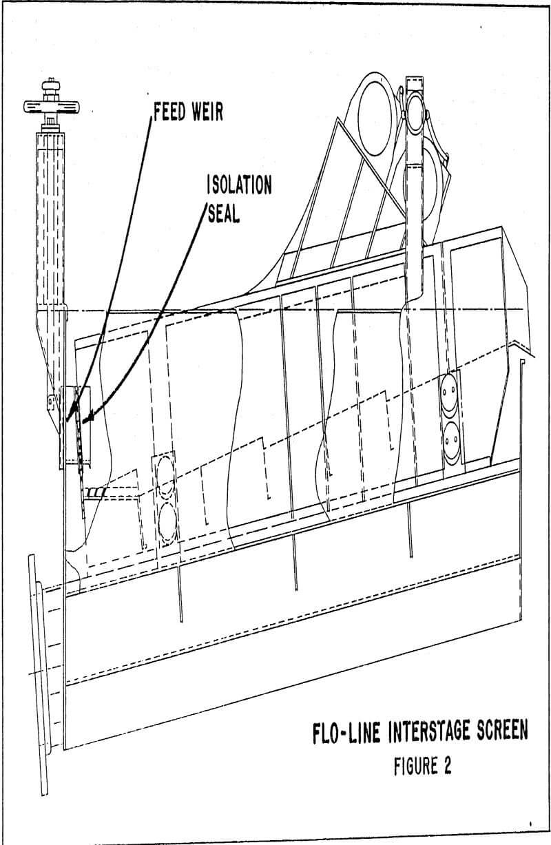
Isolation of screen undersize from process slurry necessitated construction of an outer tub with internal screen mounts. To provide slurry head for flow over the feed weir as well as carbon return, the screen deck was set at a 12 slope, Figure 2. A 0.010m Linatex seal was bolted between the vibrating screen and stationary underpan exterior for dampening purposes.
Mechanical Development – Prototype Testing
Prototype testing beqan on March 17th with a simple operations check and an eight hour motor lubrication run in. No mechanical problems were encountered and on the following bay, slurry flow was put onto the screen at a 0.050m³/s rate. This flow was easily handled on the first panel of the three segment screen. Carbon travel was extremely good requiring three to five seconds to move from the slurry pool back into the tank. There was no build up of carbon particles on the deck and flowrates of 0.100m³/s were reached upon within one hour.
Carbon-Slurry Circulation
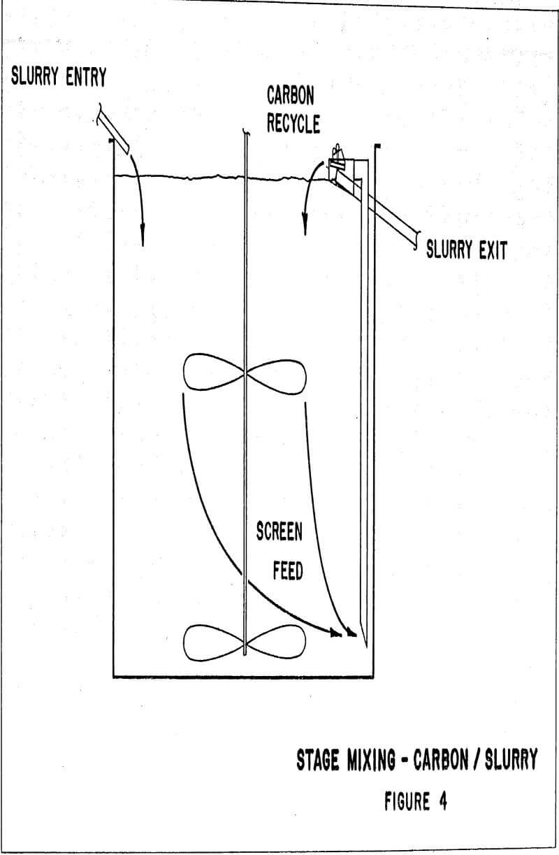
Carbon-slurry interaction can be maximised by feeding slurry into the tank at or near the surface, while drawing pulp onto the screen from an upcomer. Carbon recycled off the screen must traverse the entire tank height before returning to the inter-stage screen. As depicted in Figure 4, this flow pattern minimizes both carbon and slurry short circuiting while simultaneously eliminating localized high carbon concentrations near the screening device.
Engineering and Design
Concurrent with the Flo-line interstage testwork, Newmont Gold was engineering a conversion and expansion of its 4600 STPD No. 1 Mill to six stage CIL. Launder (EPAC) screens were originally to be installed in this modification, but with the success of Flo-line interstage screening at Mill No. 2, approval was given to utilize this technology on a production basis.
The CIL plant design comprises six 10.36m ∅ x 10.67m agitated tanks, each with a single 1.22m x 2.44m Flo-line interstage screen equipped with 0.85mm panels. The screens are fed by a 0.61m diameter upcomer. Project schedule was such that a carbon advance pump mechanism could not be designed, fabricated , and tested prior to engineering completion. In lieu of this, a recessed impeller vertical pump was suspended at the screen discharge to permit carbon rich slurry to be transferred.
Capital Cost
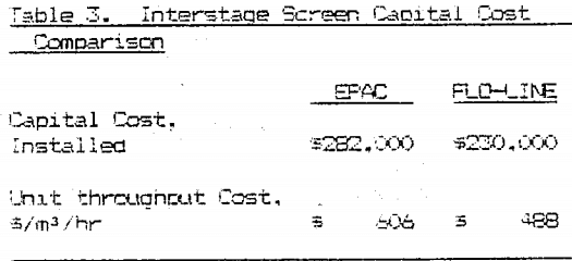
A capital cost comparison between EPAC and Flo-line interstage screen installations can be made using Newmont Sold Company’s No. 1 and No. 2 Mills. The No. 2 Mill was designed as a 7000 TPD plant and, based on the process criteria, would treat 0.129m³/s through CIP. This volume is essentially that processed by Mill No. 1 thus enabling them to be compared on a cost basis. Table 3 describes the total capital cost (1937 dollars) and cost per unit throughput for the two systems.