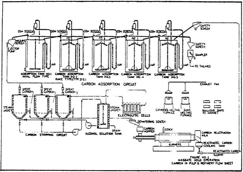
Sslurry at a rate of approximately 3.785 cu. m. per minute (1,000 GPM) is placed in contact with activated carbon. A simplified flow-sheet of the CIP Plant is shown in Figure 2.
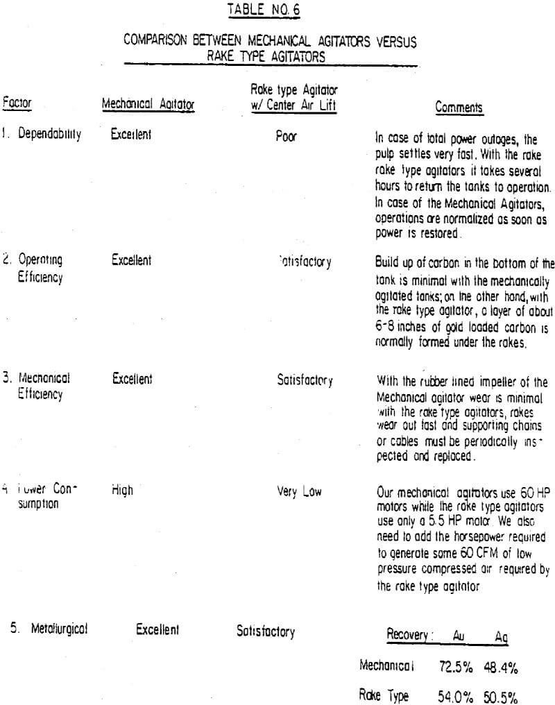
For years it has been known of the affinity of activated carbon to adsorb preferentially the gold and silver in cyanide complex form. This operation takes place in five circular tanks that provide a total pulp retention time of 5.5 hours. The carbon advances countercurrently to the pulp. The carbon is maintained in suspension in the pulp by an internal air-lift and mechanical agitation of the pulp, either with rakes or with axial flow propellers. This last arrangement is preferred because in case of power outages the pulp can be easily repulped after the power is restored. By means of an external air-lift, the pulp is elevated to the top of two back-to-back DSM Screens, such that the granular activated carbon (-6/ 10) mesh is retained on the screen surface and the finely ground pulp is piped down to the next tank in the circuit. Both, carbon and pulp, advance countercurrently by gravity. Carbon is advanced such as to satisfy daily production requirements. An adequate amount of fresh or reactivated carbon is added daily to the last tank in the circuit.
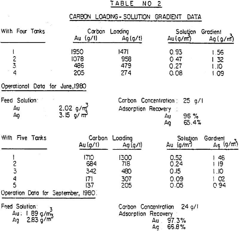
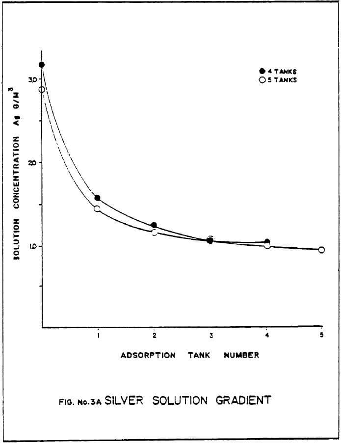
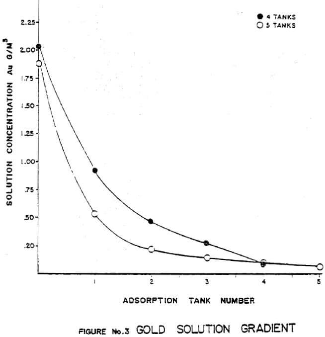
Carbon concentration in the pulp averages 24 grams of carbon per liter of pulp. Carbon loading, expressed in grams per metric ton of carbon is shown on Table 2. Typical solution gradient curves are shown on Figures 3 and 3-A. After carbon reaches a satisfactory loading, it is washed on a vibrating screen and then educated to the Carbon Desorption Circuit. A typical two-ton batch is stripped in about 14 hours. However, present facilities are such that six tonnes of carbon can be stripped in one day if necessary.
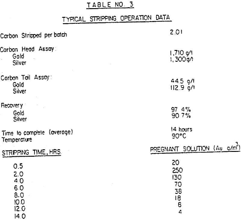
Typical stripping operation parameters are shown in Table No. 3. An alcoholic solution containing ethanol, caustic soda and sodium cyanide is heated to 90°C and pumped through the Carbon Bed. The solution has been heated with steam in a stainless steel tank. The steam is externally injected through a steam jacket of the “clamp-on” type.
For best efficiency, desorption columns, alcohol tank and piping throughout have been thermally insulated.
Adequate and basic instrumentation has been provided for the efficient operation of the desorption process.
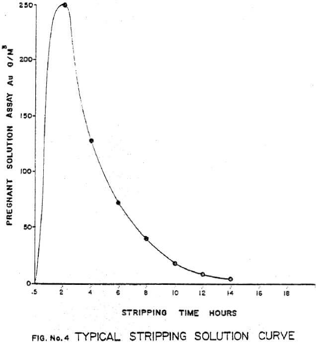
The most critical factor for an efficient desorption rate is the temperature. A drop in temperature by 10°C may increase the time for desorption by 6 hours (from a typical 14 hours to 22 or 24 hours). Figure No.4 shows a typical stripping solution curve.
Flowrate is also critical and is carefully monitored during the operation.
Floor washing and excess water generated during carbon handling is recirculated within the plant. Carbon is handled in slurry form using water jet eductors. These operate very efficiently. A booster pump rated at .38 cu. meters per min. (100 GPM) and 10 bars (145 psi) provides the necessary water flow and pressure for handling the carbon throughout the plant.
Electrowinning Circuit
The carbon stripping process requires the continuous removal of gold and silver by passing the pregnant solution through a battery of electrolytic cells.
The process continues until the gold and silver in the solution is dropped below five (5) grams of gold per metric ton of solution (5 ppm).
Gold and silver are deposited on steel wool that serves the purpose of cathodes. Anodes are made of stainless steel screen mesh.
Three rectangular cells have been designed to provide 6 min. retention time per cell. The cells are made of stainless steel insulated internally with FRP.
Direct current to the cells is provided by a rectifier rated for an output of 300 amp and 12 volts per cell.
There are two banks of three cells each. Each bank is alternatively used every month.
This method provides a very convenient system for accurately accounting metals production for any particular month. Present practice consists of removing cathodes three times a week for a total production of approximately 186.6 kg (6,000 ounces), of gold and 124.4 kg (4000 ounces) of silver per month.
The efficiency of this circuit is very high and averages approximately 97% for gold and 90% for silver.
The fire hazard involved in handling alcoholic solutions demands special precautions to avoid overheating in localized areas, rapid removal of alcohol vapors, adequate provision of firefighting equipment and close supervision of the operations around the clock. So far, no special problems have been experienced in this area.
Carbon Reactivation
This is the most important aspect for a successful CIP Plant. No matter how good the new, fresh carbon is, if the carbon is not properly reactivated, the efficiency of the carbon adsorption circuit will be low and consequently, high gold and silver losses will be experienced in the CIP Plant.
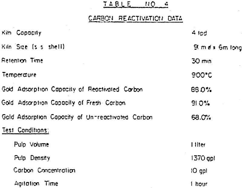
Our Rotary Kiln provide 30-minute retention time ; reactivation temperature is 900°C. The Kiln 0.91 m ∅ x 6m long (3′ ∅ x 20′ long) is externally heated with three burners equally spaced along the kiln.
Temperature controllers and indicators are installed to maintain the required operating conditions. The kiln is equipped with a variable speed screw feeder to regulate carbon feeding to the kiln.
Every batch of stripped carbon is first water drained, then water rinsed, then steam scrubbed and finally educted to the Rotary Kiln.
The quality of the reactivated carbon is periodically checked and normally compared with fresh activated carbon.
Locally manufactured activated carbon is used in the Masbate Operations with satisfactory results. Local carbon is produced from coconut shells which is abundant in the Philippines.
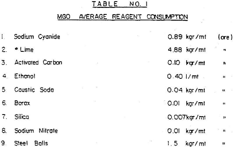
Fine carbon losses are daily measured and carefully evaluated. Although coconut is softer than peach pit carbon or walnut shell carbon, our consumption averages 0.10 kg per ton of ore, which seems to be somewhat higher than similar operations elsewhere.
Typical results on activated and reactivated carbon are shown in Table No. 4.
The regenerated carbon discharges by gravity into a conical tank where it is water cooled ; then ejected to a washing screen before being reintroduced to the Carbon Adsorption Circuit.