Table of Contents
Mineral Park Geology
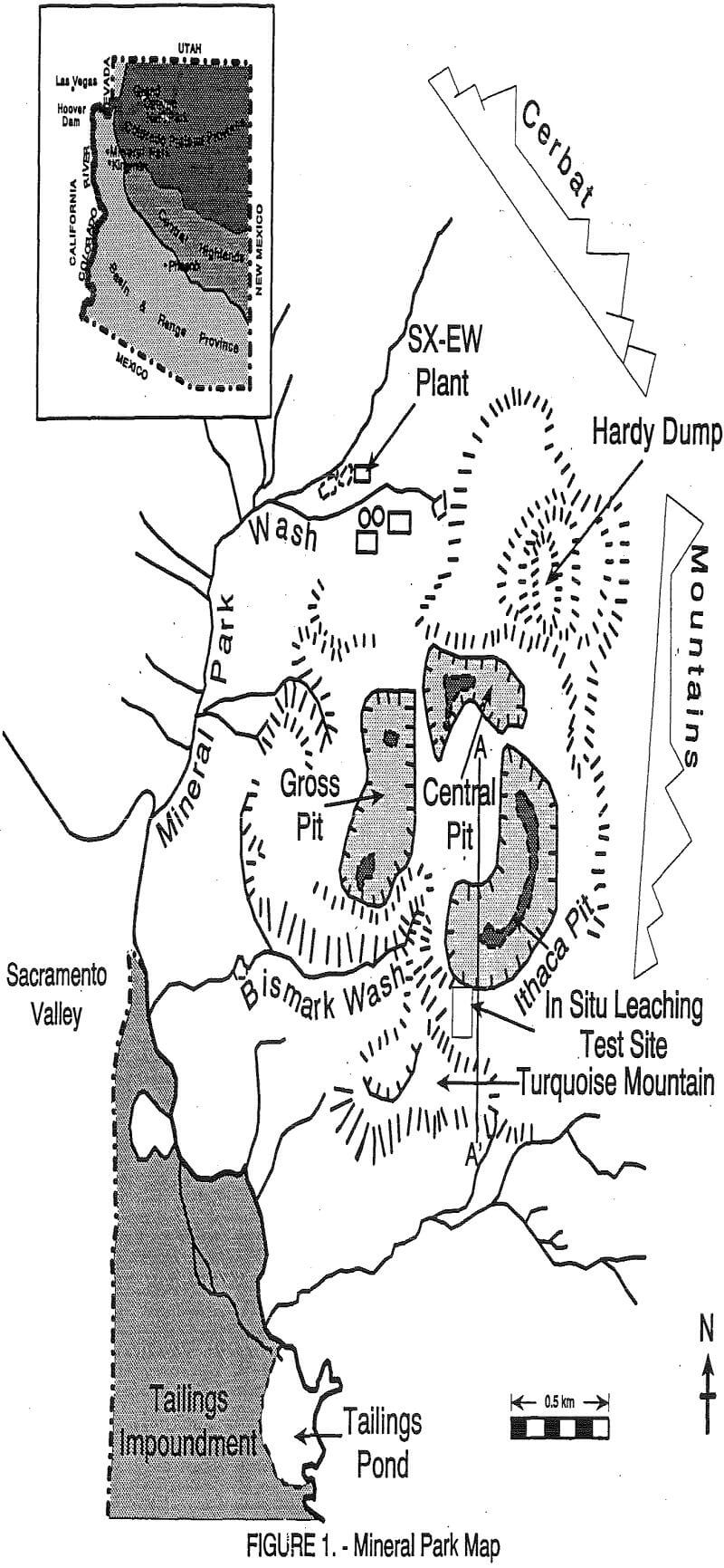
The Mineral Park mine is located in the central part of the Wallapai mining district of northern Arizona. Mineral Park is a copper-molybdenum deposit within and adjacent to a Laramide quartz monzonite porphyry intrusion. Minable copper reserves have been estimated to exceed 40 million tons of .2 pct or greater. The geology and mineralogy of the Mineral Park deposit has been described by Thomas, (1949), Eidel et al (1968), Wilkinson (1981), and by Lange and Eastoe, (1988).
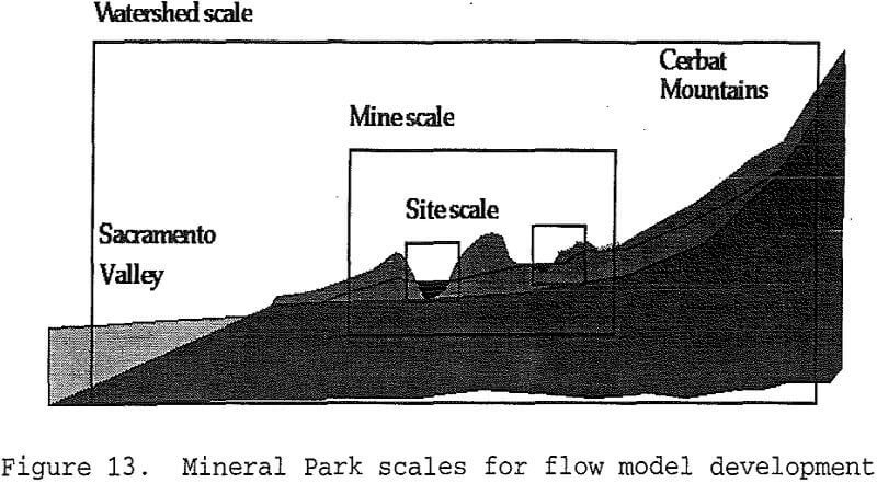
Turquoise Mountain Test Site
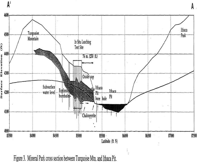
The site covers approximately 7,000 m² and is bounded on the north by Ithaca Pit, on the west by Bismark Wash and by leach dumps which drain into Bismark pond. On the south, the site is bounded by Turquoise Mountain and beyond that, by an unnamed wash which drains onto the Mineral Park tailings impoundment. On the east, the site is bounded by additional mine developments at higher elevations.
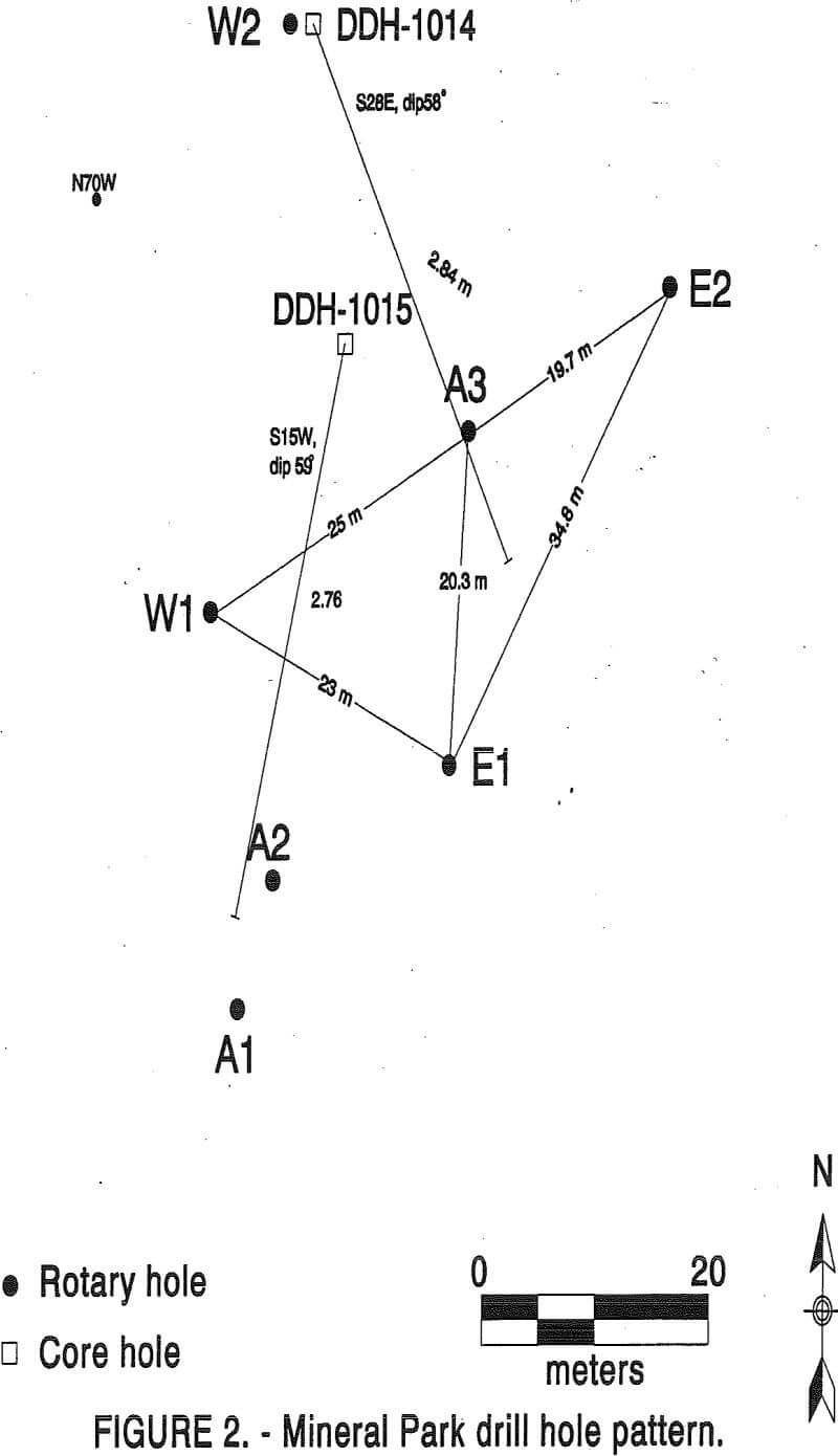
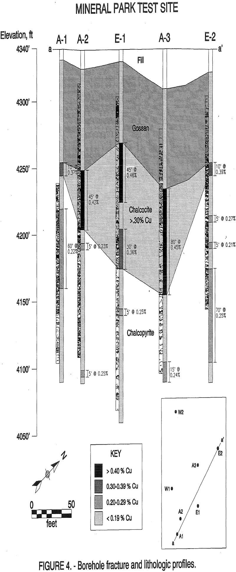
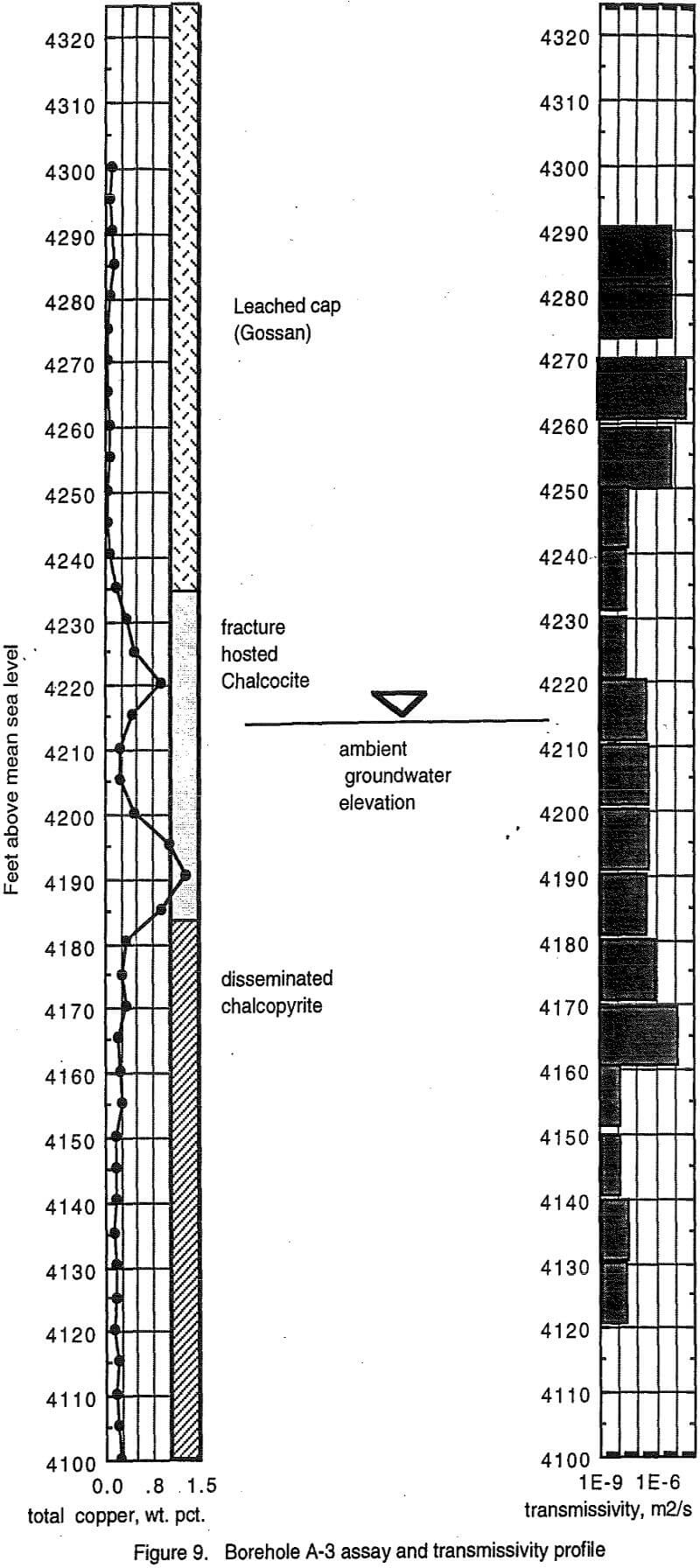
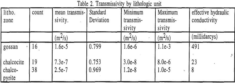
The chalcocite enrichment blanket is composed of two to three layers of higher grade ore (0.4 to 1.3 pct Cu), from 6 to 12 m thick, separated by thinner layers of lower grade ore (<0.2 pct Cu). The average grade in the enrichment zone is 0.41 pct Cu. Chalcocite is precipitated on pyrite surfaces and is two to four times the grade of the underlying primary ore. Smectite clay veins are associated with chalcocite in drill cores of the hornblende/metadiorite host rock. A thicker zone of enrichment and higher average grade in the S28E (DDH 1014) core hole than in the S15W (DDH 1015) core hole suggests that the northeast trending fracture set may be the locus of secondary copper enrichment at the test site.
Groundwater Chemistry
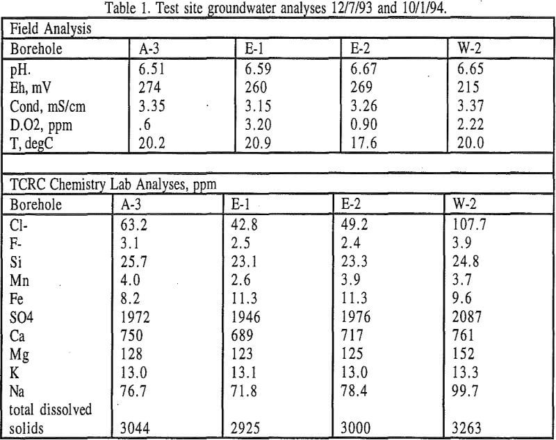
During pumping tests conducted in December 1993 and October 1994, groundwater samples were obtained from the test site. Samples from boreholes A-3, E-2, E-1, and W-2 were obtained in accordance with the Arizona Groundwater Quality Assurance Project Plan (1991), which calls for a three well bore volume purge prior to collecting samples. All samples were filtered through a 0.2 micron filter within 1 hour of collection, and sample splits were acidified with nitric acid within 12 hours of collection. Comprehensive analyses were performed at the Twin Cities Research Center (TCRC) laboratory. In addition, the pH, temperature, Eh, dissolved oxygen content, and conductivity of the sample were determined in the field within 1 hour of collecting the samples.
The groundwater compositions are being processed using geochemical software EQ3/6 (Wolery, 1992) in order to determine the aqueous speciation and mineral solubility controls on water composition. The results of the chemical equilibrium program show that gypsum and amorphous silica are saturated in all of these groundwater samples. Fluorite (amorphous aluminum silicate) is also saturated in all samples.
Borehole Televiewer Survey
Televiewer surveys were conducted in all seven boreholes, by the USGS. The borehole televiewer is a rotating acoustic camera which produces a continuous acoustic image of the borehole wall, as it is raised in the borehole. Photographs of the televiewer image reveal the location and orientation of fractures and other voids in the borehole wall (Paillet et al, 1987). Fractures that are completely filled with clay or precipitates may be present, but cannot be detected in an acoustic image.
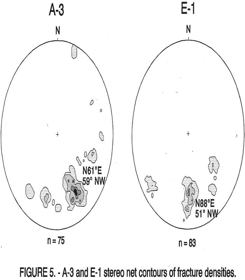
All three lithologic horizons, weathered cap, enrichment blanket (Cu >0.3 pct) and primary ore, appear densely fractured, although the highest concentration of borehole fractures is found in the unmineralized oxide cap. It is difficult to, to see a correlation between fracture intensity and ore zone lithology, although there is some hint (in the A-3 log especially) that fracture intensity in the enrichment zone may be diminished somewhat, relative to the primary ore underlying it.
The absence of northeast trending fractures (visible to the acoustic televiewer) in the enrichment blanket again suggests that mineral-rich fractures may be invisible because of associated clay fillings.
Borehole Hydrogeologic Testing
While a large number of fractures may be encountered in a borehole drilled into fractured rock, often only a small percentage of these conduct measurable amounts of water into the borehole during pumping (Long 1991).
Fracture-flow modeling studies by Long et al (1982), Endo et al (1984) and Long and Witherspoon (1985) have revealed that the hydraulic behavior of fractured rock formations is determined mainly by the geometry of connections within the fracture system.
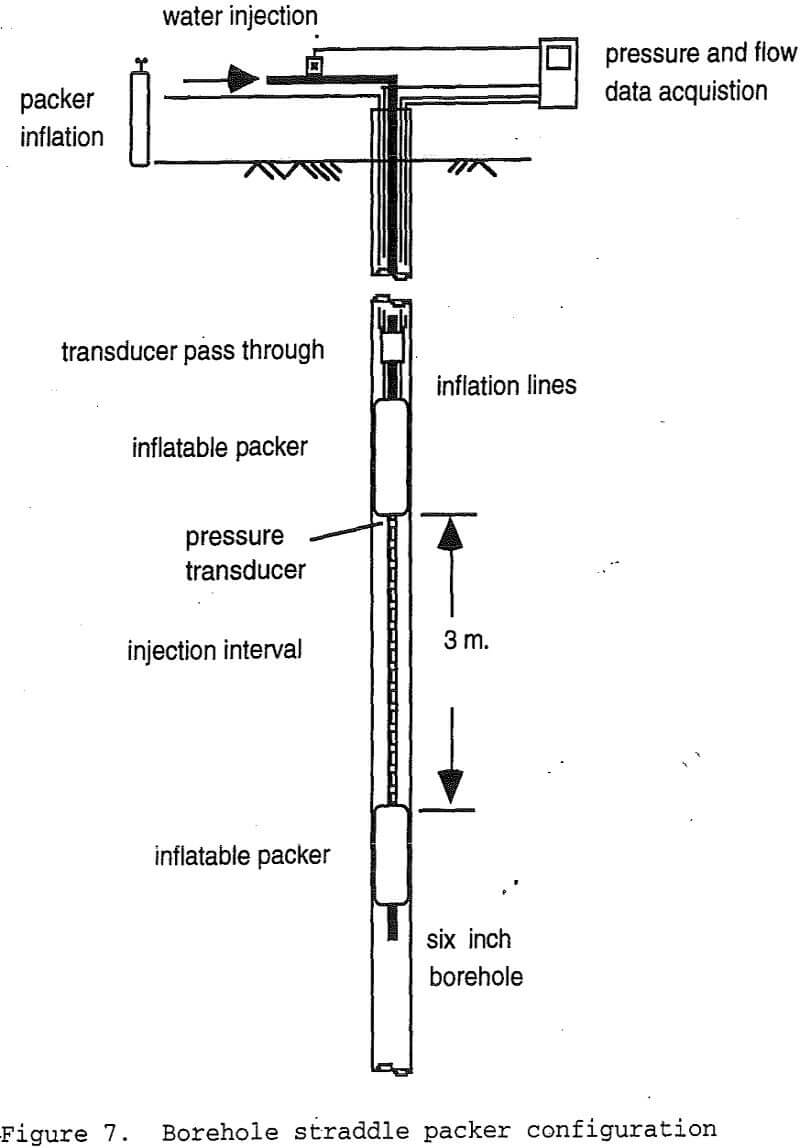
Borehole hydrogeologic testing has involved single borehole straddle-packer injection tests, and multiple borehole pumping tests. A truck-mounted wire-line winch-and-boom assembly was used for raising and lowering pumps and packer assemblies in the boreholes. Down-hole pressure transducers were used to monitor changes in borehole pressure. In-line flow sensors, and flow controllers were used to monitor flow and to maintain constant flow conditions during tests. Pressure and flow data were recorded using an automated data logger.
Borehole Straddle-Packer Tests
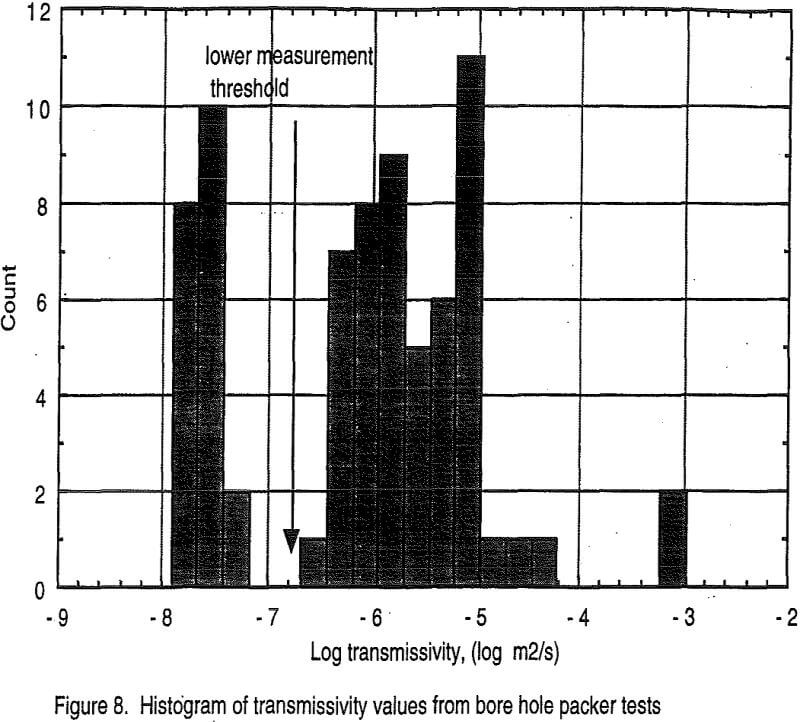
Straddle-packer data analysis followed the methodology presented in Groundwater Manual published by the Water and Power Resource Service (1981) as originally developed by Zanger. This semi-empirical method estimates transmissivity coefficients for (saturated) semi-spherical flow around the packer interval using Darcy’s law, and by imposing an empirical shape factor which describes the flow envelope around the borehole injection interval.
The Zanger method, while approximate, is applicable to intervals both above and below the water table. Since the weathered cap rock and about half of the enrichment blanket are above the ambient water table at the site, and since this portion of the deposit will ultimately be saturated with leach solution, it is desirable to estimate transmissivity (under saturated conditions) 20-25 m above the present water table.
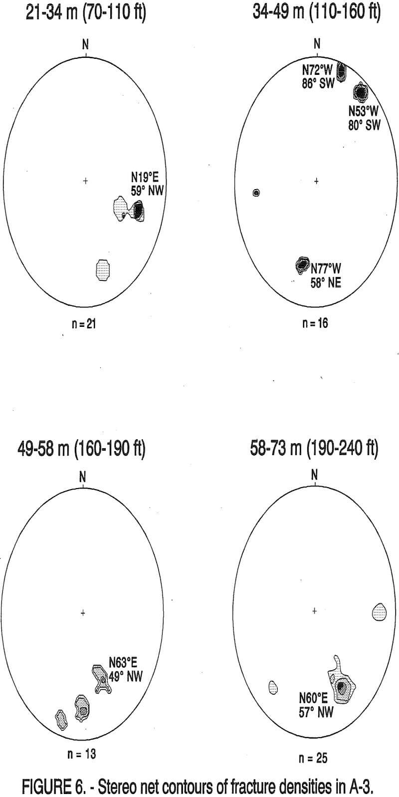
The highest transmissivity values in A-3 are observed in the weathered cap rock above the water table. Transmissivity in the upper layer of the enrichment blanket (which is still above the water table) is lower by at least two orders of magnitude. Transmissivity increases somewhat when the packers are situated at the bottom of the enrichment zone. The highest transmissivity below the water table is associated with a fractured interval just below the enrichment blanket, at 4140 MSE. This interval contains four open fractures trending north and northeast (N2W to N47E). All the fractures are east dipping (39E to 70E). Below this elevation, the A-3 profile shows four consecutive no-flow intervals.
Borehole Pumping Tests
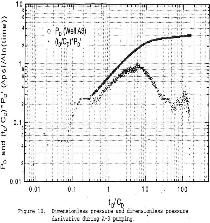
Pumping tests have been conducted in four of the boreholes at the test site The preliminary analysis of A-3 pumping data is based on application of a double porosity conceptual flow model, first introduced by Barenblatt et al (1960). The main assumptions of a double porosity model of flow in fractured rock are presented by Gringarten (1984) as follows.
- The hydraulic conductivity of the fractures is substantially higher then that of the blocks.
- Flow into a borehole occurs exclusively through fractures which intercept the borehole.
- The blocks supply water to the fractures in response to pressure differential between fractures and blocks, that develops during well pumping.
- An infinitesimal volume of the rock contains a large proportion of both fractures and blocks, so that each location in the fractured rock is associated with two pressures, a fracture pressure and a block pressure.
In the double porosity model, the drawdown response, s, that is observed in a monitor well a distance, r, from the pumped well, is given by Kruseman and de Ridder (1990) as,
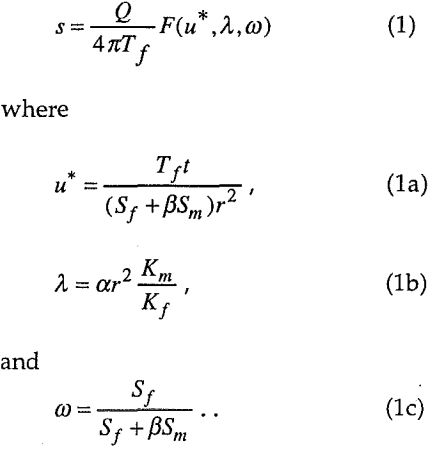
The argument u (=l/u), in equation 1, is associated with the Theis exponential integral solution for flow in an infinite acting porous media. The arguments, ω and λ, are associated with the fluid exchange between blocks and fractures that occurs during pumping; λ is the ratio of fracture to block hydraulic conductivity, and ω is termed the interporosity flow coefficient; ω, is the ratio of fracture storativity to total storativity.
The other variables in these equations are:
Q = borehole flow rate (l³/t)
T = effective transmissivity (l²/t)
S = storativity (dimensionless)
K = hydraulic conductivity (l/t)
a = shape factor characteristic of number of fracture sets
β = factor characteristic of fracture geometry
The subscripts f and m denote properties of fractures and matrix blocks, respectively.
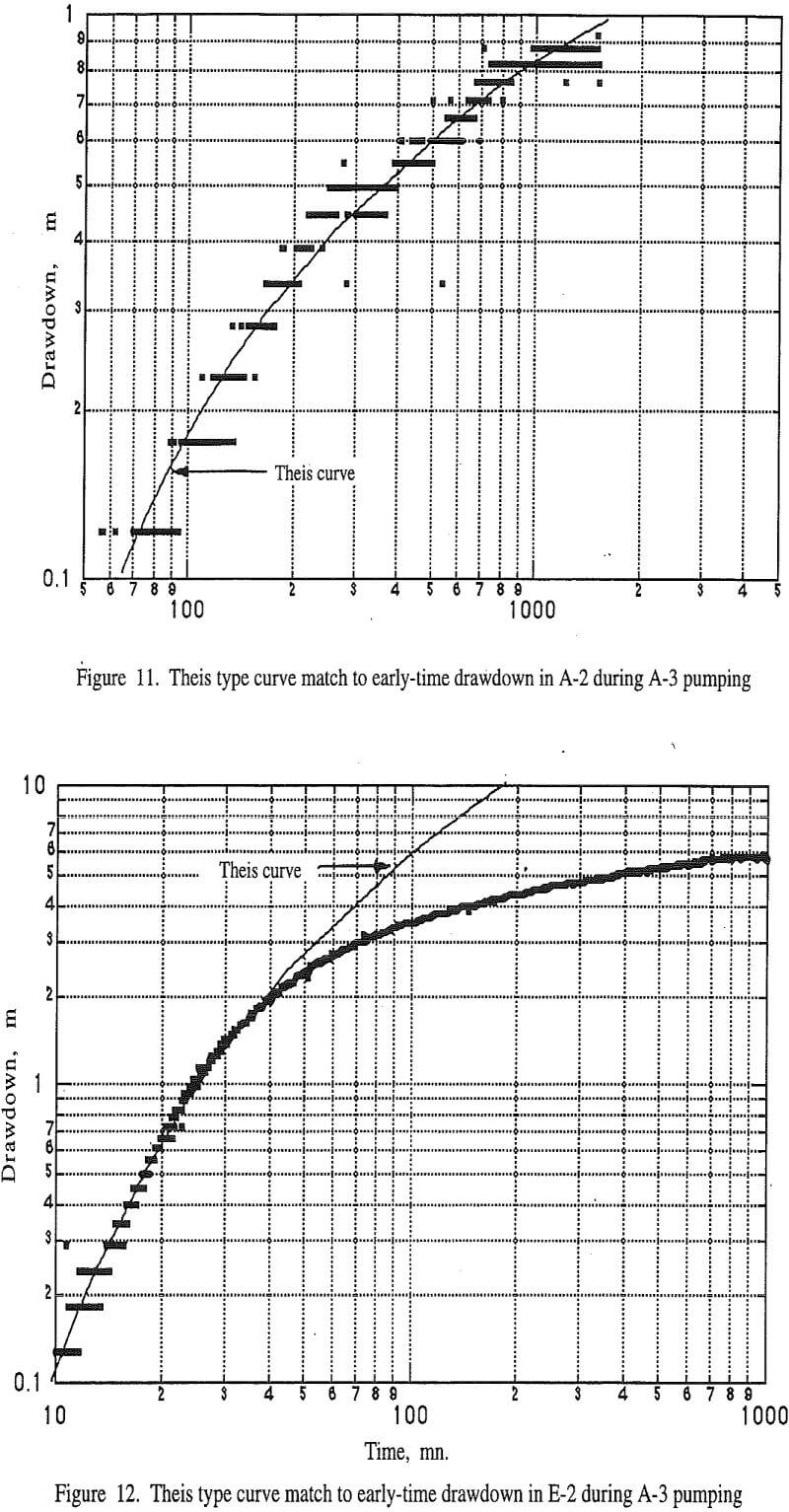
The early-time Theis analysis of E-2 data during A-3 pumping yields,
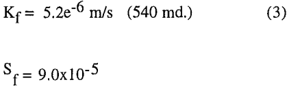
Substituting the E-2 results and the previously calculated interporosity flow parameters into 1b and 1c yields,
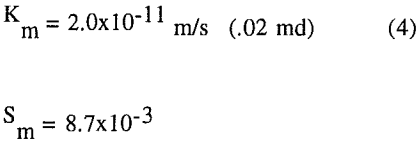
for matrix hydraulic conductivity and storativity, respectively.
Discussion of Test Results
Kruseman and de Ridder indicate that values for the interporosity flow coefficient, λ oil, range from 10-³ to 10 -9, and that values for storativity ratio, ω, range from 10-¹ to 10 -4. The equivalent λ value for A-3 is 1.3 x 10 -6. Thus both ω and λ appear to be in a reasonable range for fractured formations. The type-curve estimates of transmissivity and storativity from A-3 and E-2 also appear reasonable when compared to other published data regarding the relative magnitudes of hydraulic conductivity in fractured and unfractured igneous rock. While it is typical for transmissivity of fractures to greatly exceed that of porous blocks, storativity of fractures is typically less than that of the blocks. The values of Sf and Sm that were obtained from type-curve analysis are in a range normally associated with confined aquifers (Freeze and Cherry, 1979).
The depth and length of the transition period in figure 10 are controlled by the storativity ratio ω. The ratio of fracture storativity to total storativity in the ore deposit is comparatively high, which in turn means that the transient period of block to fracture flow is comparatively short. (This makes it difficult to detect using the drawdown curve alone.) The relatively short transition interval means however that the interporosity flow between fractures and matrix could be assumed to reach a pseudo steady-state condition relatively quickly (Clark, et al, 1985). Equilibrium between fracture and block flow appears to be approaching after 13 hours of pumping but has not been achieved. Clearly, additional long term pump and recovery testing is needed to verify the preliminary results presented here.
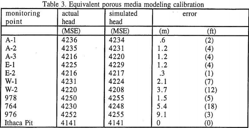
Equivalent Porous Media Hydrologic Modeling
Preliminary interpretation of straddle-packer and pumping test supports the assumption of a single, infinite acting homogeneous porous media for flow modeling investigations conducted on a scale that is somewhat larger than the test-site itself.
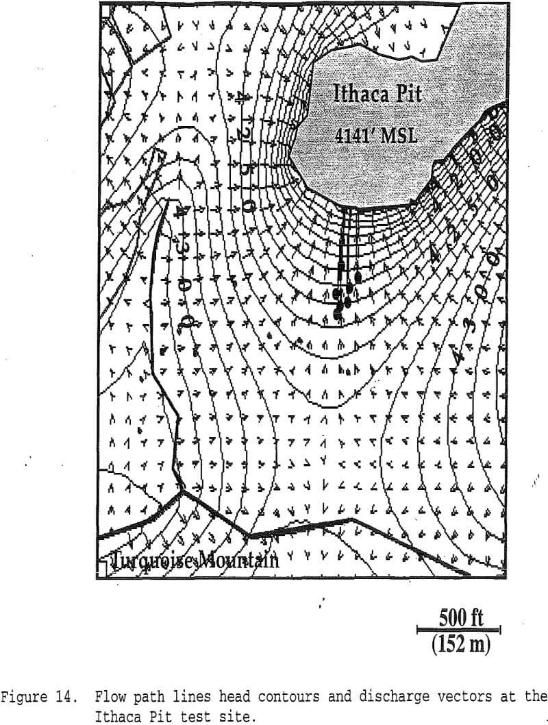
The single porous media model of the mine property south of Ithaca Pit was calibrated using known water levels at the locations of the seven boreholes on the test site, three nearby monitor wells, and the known elevation of water in Ithaca Pit.