We used the original flowsheet for two and a half years and made concentrates containing 16%-18% insol. Then we were asked to reduce the insol content as much as possible without additional capital expenditures in an effort to improve the smelting process. One of the 7 x 10 bail mills had been outfitted with four D10B Krebs cyclones several years previously for a concentrate regrind test on Row 1 of the sulfide roughens. The small mill obviously could not handle the tonnage of rougher concentrate from five rows and we doubted that it could handle ever, the first cleaner concentrate. But we tried it. It didn’t. Back to the drawing board.
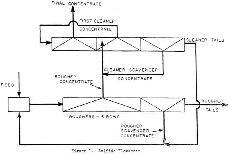
Sampling of each cell of the cleaner row when the new cells were installed had established that the first two cells of the first cleaner bank made a concentrate grade higher than the final concentrate over 90% of the time. The completely liberated mineral particles are fast floating and pop to the surface immediately. So we decided to take advantage of this by routing the high grade froth from the first two cells directly to the final concentrate sump. We hoped that this would reduce the tonnage going to the little mill by as much as one-third. The froth from the last three cells of the bank contained the locked minerals that really needed regrinding. The idea worked beyond our expectations and the insol content was reduced to the 12%-14% level.
Later, approval was received to install one concentrate regrind mill.
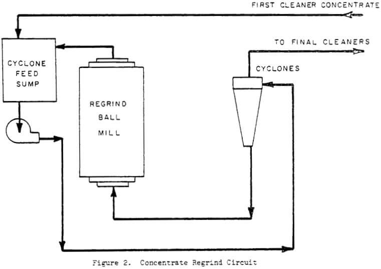
It had been calculated that three 670 kW mills would be required to handle the tonnage of rougher concentrate but that only one 450 kW mill would be necessary to treat the first cleaner concentrate. The regrind circuit was designed accordingly with the flow shown in Figure 2.
The first cleaner concentrate is pumped to a cyclone feed sump that also receives the regrind mill discharge. The combined pulps are pumped to a pod of four D205 Krebs cyclones. The cyclone overflow is pumped back to the head of the final cleaner bank and re-floated to produce a final cleaner concentrate The cyclone underflow drops down into the mill feed spout.
The regrind mill is a 8.2 m x 4.27 m Allis-Chalmers overflow ball mill with a 450 kW motor operating at 14.8 rpm. The mill is charged with 2.5 cm ARMCC Moly-Cop forged steel balls.
The D20B Krebs cyclones are fitted with 125 cm² inlets, 15.2 cm diameter Ni-Hard vortex finders and 6.35 cm diameter Refrax apexes.
Initially the mill was charged with enough bails to draw approximately 860 kW. The ball load has been increased at times so as to draw as much as 860 kW. The grind improved but was not accompanied by further reductions in insol in the final concentrate.
To date, two cyclones handle the feed most of the time. The cyclone underflow density which is also the mill discharge density, ranges from 70%-75% solids. The overflow density hovers around 15% solids. Although the cyclones are operating well below the design pressure of 100 kPa, screen analyses of the final concentrate averaged 81% minus 44-microns for the first five months of operation.
Overall the regrind circuit is meeting its objectives. The reduction in insol content has been greater than expected. For the first years of operation with the WEMCO cells and no regrind at all the insol level ranged from 16%-18%. The next four years of operation with the temporary regrind circuit yielded insol levels ranging from 12%-14%. The new regrind facility has cut the insol content in half, averaging 7% for the first months of operation.
The regrind circuit is not conventional, but it works.