
- To participate in the 911Metallurgist Forums, be sure to JOIN & LOGIN
- Use Add New Topic to ask a New Question/Discussion about Thickening, Filtering or Tailings and Water.
- OR Select a Topic that Interests you.
- Use Add Reply = to Reply/Participate in a Topic/Discussion (most frequent).
Using Add Reply allows you to Attach Images or PDF files and provide a more complete input. - Use Add Comment = to comment on someone else’s Reply in an already active Topic/Discussion.
Horizontal vacuum belt filter design (5 replies)

In order to determine the filtration area, it is important to know the initial percent solids, other important data is the filtration rate. All the material has not the same filtration characteristics, which is influenced by several factors, for example the particle size. You need to conduct basic filtrations tests with your zeolite.
Filtration
The usual test apparatus is a small filtering surface reproducing essentially the type of surface to he investigated. The Oliver Filter Co. uses a filter-lenf frame of the form shown in Fig. 147, item Y, made of Bakelite, cast in one piece.
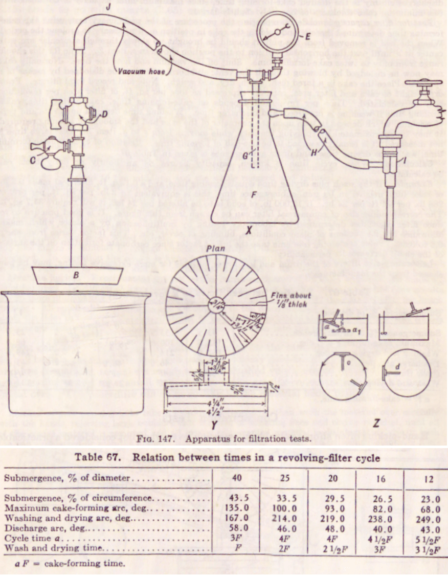
A stainless-steel band, with inside dimensions about 1/32" larger than the frame, is provided. To prepare the test leaf, a piece of filter cloth is cut large enough to cover the frame and turn down over the edges; it is placed over the frame, and the band is forced down so that the cloth makes a tight fit at the edges. The filter leaf is then connected into the typical test-leaf hookup shown in item X, comprising a container A for the slurry, with means for maintaining suspension; the test leaf B; flexible connecting piping containing a vent, cock C and shutoff cock D, and attached to a vacuum gage E or a mercury manometer or other pressure-measuring device; a vacuum receiver F, which is preferably transparent and large enough to receive a graduate under the filtrate pipe G, so that filtrate volume can be read directly during operation; and connection H to a source of vacuum, which is conveniently a water aspirator I, as indicated.
Test procedure is designed to simulate the cycle of a particular type of filter. For example, the cycle of a drum-type filter may be broken down into (1) a cake-forming stage, during which the cloth is submerged in the pulp and is under vacuum; (2) a cake-drying stage during which cloth is out of contact with the pulp but still under the action of the vacuum; (3) a cake-discharge stage begins when the vacuum is shut off and ends with resubmergence.
In testing to parallel plant performance, the test pulp should have the same temperature, pH, and state of dispersion as the pulp to be supplied to the filter in the mill. The test should be performed at such pressure as will be available at the mill; elevation of mill above sea level and vacuum equipment to be used are the controlling factors.
Preliminary run is made to determine the time required to form a dischargeable cake. With stopcocks C and D closed, introduce test leaf as at a, item Z; when immersion is complete, turn on vacuum, which will have been built up to the desired level in F, and note time; move leaf slowly through the well-stirred pulp, following a circular path; note vacuum; finally, bring leaf out of pulp as shown; shut off vacuum, and note time. The time elapsed is the cake-forming time. The cake should be dried and its thickness determined by placing several pieces on top of each other, measuring total height and computing average thickness. The time required to produce minimum thickness of cake that discharges cleanly is the desired cake-forming time, since maximum filter capacity is obtained with this minimum cake thickness or one only slightly larger.
Test for filter capacity is made by repeating the procedure of the preliminary test, using the cake-forming time determined therein, and holding the cake in position ai, if necessary to prolong the period. When the leaf is removed from the pulp it should De brought up slowly through a circular arc with center at J until past the horixontal position to the position shown in c, item Z. Time for this should range from once to twrice cake-forming time. Shut off the vacuum and note the time. Normally cake may now be dislodged by blowing through the vent; stubborn cake must be dislodged by means of a spatula. Place the cake in a tared dish, weigh, dry, and weigh. Note and record total filtrate. From dry weight of cake and filter area, capacity expressed as tons per sq. ft. of filter area per revolution may be calculated. Time per revolution depends on cake-forming time, cake-drying time, cake-washing time if washing is practiced, and discharge time. Washing time depends upon rate and type of washing, which depend in turn upon the character of the cake and the amount of cleaning required. It may be approximated by spraying the cake while moving from c to d, item Z. Discharge time is not measured; it is usually assumed to be one-half of forming time. Relation of cycle time to forming time, wash plus drying time, and drum submergence is given in Table 67.
Calculation. When cycle time is known, capacity figures on an hourly or daily basis can be calculated.
Example. If the wash plus drying time equals forming time, and a 0.1-sq. ft. filter leaf made 0.2 lb. of cake (dry weight) in 1/3 minute submergence time, this is equivalent to 2 lb. per sq. ft. per rev. or 288 lb. per sq. ft. per 24 hr. If 10,000 lb. of solid is to be filtered per 24 hr., it will require 34.7 sq. ft. The corresponding six© of commercial filter can be chosen from this figure. It is good practice to reduce filter capacities determined by laboratory testing by multiplication by a factor which makes allowance for fluctuations of plant conditions, blinding of cover, etc. This factor varies from about 0.8 to 0.6.5. Pulps containing free lime take the lowest factor since carbonate formation on the surface of the cloth decreases its permeability.
Laboratory-size filters of the drum and leaf types, suitable for more extensive testing, may be purchased from the manufacturers.
https://www.911metallurgist.com/blog/laboratory-pressure-filtration
https://www.911metallurgist.com/blog/filtration-leaf-filter-testing
Reference: Handbook of Mineral Dressing; Ores Industrial Minerals (Wiley Engineering Handbook)
by Arthur F. Taggart
Use the Social Share Bar on the Left. Tell everyone you can about https://www.911metallurgist.com/metallurgy/ It's FREE & GOOD.
Thanks to all, its help a lot, I already finish horizontal vacuum belt filter design but there are some other problems appear in the process. Suddenly our professor came up with a thickener design for decrease the filter area. I don't think thickener is a good idea for our continuous process but I don't have a choice at that point. Filter and thickener design requirements are much specific, unlike pumps or heat changers. Unfortunately, our deadline is coming closer. I can't simply make an experiment to find our design values. If you have some documents for thickener design for zeolite A or similar to this, please share with me.
Hi Pefh, can I ask for your design as preferences? I am doing horizontal vacuum belt filter design for phosphoric acid production from phosphate rock and I don't know how to size this. If could, please give me the documents how to size this type of filer. I really need help. Thank you.
Jeremy
Hİ, I am chemical engineer student and in our design project, I have to design horizontal vacuum belt filter for zeolite production and I can't decide how much filtration area? How can I calculate? our slurry masses 11000kg per hour. please I need help.