Table of Contents
The heavy postwar demand for Portland Cement has created shortages that are gradually being overcome by increases in plant capacity. In the postwar period, the Lone Star Cement Corp. has expanded several of its existing 15 plants and has built 2 new plants, now in operation, with a third new plant under construction in Brazil, of design somewhat different from that of the two preceding ones.
Raw Materials
The chemical composition of Portland Cement raw material after crushing, grinding, and mixing, but before burning, is about as follows:
Shales and clays generally do not contain sufficient SiO2 and Fe2O3, and these components must, therefore, be added in the form of sand, iron ore, and sometimes tailings from an iron ore concentrating plant. Certain objectionable materials occur in raw mix: magnesia, limited in cement to 5 pct, in excessive amounts; alkalies, as sodium and potassium; phosphorous; and sulphur, generally present in coal and oil.
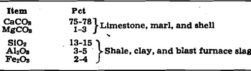
General Plant Layout and Construction
The two plants are so similar that one joint description will cover both, with such exceptions as will be especially indicated.
The crushing plant is located in the quarry, and raw material is conveyed by belt to the storage building, where all materials are stored and handled. The large storage building is used for the storing and handling of all materials, including limestone, shale, sand, iron ore, coal, clinker, and gypsum. Directly adjoining the storage building is a structure under a similar arched roof, containing the raw and clinker grinding departments and the electrical substation. The discharge ends of kilns and coolers, and coal or gas burning equipment are also placed at one end of the mill building. The 340-ft long kilns extend away from the main buildings to form the long leg of an L, at the end of which is the feeding and kiln dust collecting equipment, and the raw blending silos are conveniently located adjacent to the feed end of the kilns.
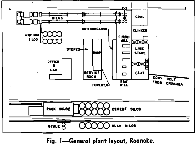
An Eriez Metal Detector is installed at the belt conveyor leading from the primary to the secondary crusher. It consists of a detector coil which circles the belt, and an electronic control cabinet. When a
piece of tramp metal, magnetic or nonmagnetic, passes through the coil, the belt and primary feeder are stopped and a horn is blown. The operator then knows the spot where he will find the tramp metal, and after its removal he restarts the equipment. This device and a similar detector which has been in use for about 18 months at a Lone Star crushing plant in Alabama have resulted in the discovery and removal of much objectionable metal that would otherwise have caused extensive damage.
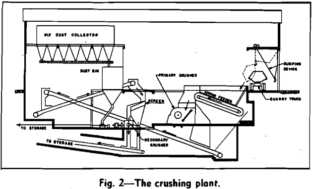
Drying and Raw Grinding
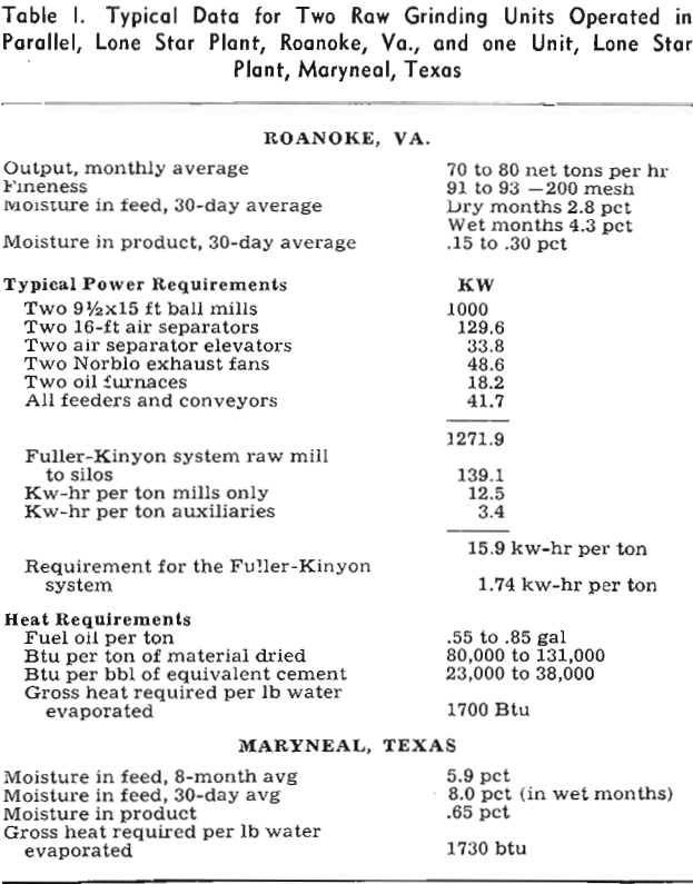
Raw materials are delivered by bucket crane to the raw feed hoppers. Merrick Feed-O-Weights measure out each material in the required proportions and the mixture is then delivered to the raw ball-mill feed bins. From here it is withdrawn as required; the feed rate is manually controlled by the operator who occasionally checks the recording ammeter connected to the air separator elevator motors. A circulating load of 500 pct is maintained.
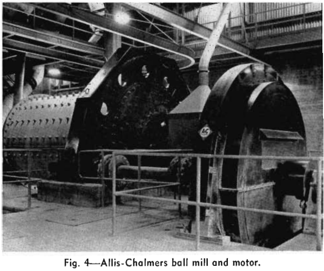
Two completely separate raw grinding units are employed. Each unit is composed of a 9½-ft diam by 15-ft single compartment Allis-Chalmers ball mill driven by a 700 hp motor, operated in closed circuit with a 16-ft Sturtevant air separator driven by a 100-hp motor.
Burning and Cooling
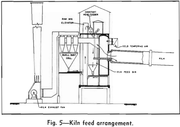
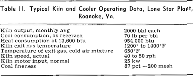
Each kiln is nominally rated at 2000 bbl output per day, and the burning zone temperature is about 2700°F, see Table II. They are fired at the lower end, the fuel being coal in Virginia and natural gas in Texas. Feeders are synchronized with drives to maintain a constant bed depth within the kilns.
Raw material is fed into the upper end of the kilns with horizontal screw conveyors, and the short drop from screw to kiln lining results in little dusting. This method is recommended as a great improvement over the conventional long inclined feed spout so often used. Fine raw mix drops from such a spout with a splash, and much material is then airswept out of the kiln.
Since the dust collectors and fans are constructed of ordinary steel, a maximum gas temperature of 700°F must not be exceeded. This is provided for by mixing cold air with 1300°F gases from the kiln.
Clinker Grinding
The three main feed bins are placed within the storage building, one being reserved for clinker, one for limestone, and one for gypsum. Materials are drawn from the bins by means of totally enclosed Feed-O-Weights discharging into a drag conveyor, which in turn delivers the material to an elevator discharging to a second drag which fills the individual bins feeding each mill.
To prevent segregation, the individual mill bins are small, and individual feeders deliver feed to the mills at a rate determined by the power consumption of the elevator feeding the air separator. If the circulating load, which normally amounts to, say, 300 pct, increases or decreases below the desired value, a corresponding response appears on a recording ammeter and an adjustment is made manually by the operator.