
Table of Contents
The effect of fluoride inclusions on the properties of titanium produced from the Bureau of Mines developed induction slag melting process is of concern to members of the titanium industry. The objective of the research was to determine the effect of CaF2 inclusions on the properties of titanium and its survival rate during melting. The data were obtained from single-induction-slag-melted ingots prepared with the normal addition of 4 pct and also with 2- and 1-pct additions of CaF2 slag.
The results of this effort showed that the mechanical properties of single-induction-slag-melted Ti-6Al-4V alloy exceed the minimum values specified in Aerospace Materials Specification for Titanium Alloy Bars and Forgings AMS4928H, but these materials are much more notch sensitive in fatigue than normal Ti-6Al-4V alloy titanium. First and second vacuum-arc remelts of single-induction-slag-melted ingots fragmented and increased the number of inclusions, while reductions in the amount of flux resulted in an upward trend in the spatial distance between pores in an x-y plane.
The Bureau of Mines has been active in the development of titanium and zironcium technology since the first commercial introduction of these materials. Bureau personnel have made significant contributions to sponge reduction processes, melting, and casting technology for titanium.
The induction slag melting process was developed by the Bureau for the purpose of consolidating loose titanium scrap into electrodes for melting in consumable-arc furnaces used by the titanium industry. The anticipated titanium scrap surplus market never developed, but the Bureau has continued work on the process because of increasing interest in it for melting a variety of metals and alloys.
The fluoride inclusions studied in this research form as a result of using calcium fluoride as a protective salt during melting. Prior to this research, the effect of these inclusions on the properties of titanium and their survival rate during remelting operations were unknown. Continuing interest in induction slag melting by the titanium industry will depend on the effect these inclusions have on the properties of titanium.
During the period of this investigation, researchers at both the Duriron Co. Dayton, OH and the Bureau successfully induction slag melted titanium and titanium alloys without slag. This subject will be covered in a separate report.
Materials
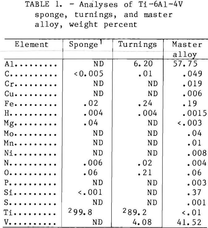
The titanium alloy chosen for this study was the widely used Ti-6Al-4V, for which data on mechanical and fatigue properties are readily available. The titanium sponge and Al-V master alloy were prepared from domestic sources. The unalloyed sponge was commercially produced, Kroll process, vacuum distilled, and in the size range of minus ¾ in by plus 20 mesh. The Ti-6Al-4V machine turnings were purchased from a commercial producer. Analyses are shown in table 1.
Luminescent-grade CaF2 was used as the insulating salt required by the process. The CaF2 was treated prior to use by first heating for 2 h in air at 1,112° F (600° C) to 1,202° F (650° C) to remove excess moisture. The CaF2 was then vacuum fused to remove any remaining moisture and CO2 resulting from the decomposition of CaCO3. Any SiO2 present and the CaO resulting from the decomposition of the CaCO3 were not eliminated during vacuum fusion, and both were a potential source of oxide contamination to the ingot.
Procedure
Ingot Melting
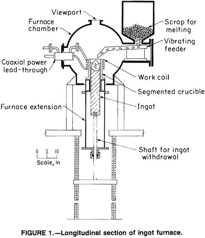
Figure 1 shows a schematic diagram of the induction slag melting (ISM) furnace. The essential features of the furnace, in addition to the segmented crucible, were a vacuum-tight chamber for melting in a controlled atmosphere, a system for side- feeding metal and insulating salt into the crucible, and a mechanism for withdrawing the ingot that was formed. Power for melting was supplied by a 100-kW, 9,600-Hz motor-generator rated at 440 V and 228 A. A detailed description of ISM as practiced by the Bureau of Mines may be found in reference 2.
Ingot Processing
Ingot breakdown was done in a hydraulic press fitted with open flat dies for close control of the deformation rate.
The rated capacity of the press is 454 mt (500 st). The ingot surfaces were conditioned with a lathe to provide defect- free surfaces prior to forging. The ingots were placed into a furnace, pre-heated to 2,050° F (1,121° C) and soaked for 2 h prior to the start of forging.
Each ingot was upset forged to 50 pct of its length and then placed into an-other furnace set at 1,875° F (1,024° C), and soaked for 30 min. After the 30-min soak, the ingot was reforged to an octagon shape of the approximate original length in the axial direction (minimum of 30 pct reduction). Following this forging operation and between each succeeding forging operation, the ingot was soaked for 15 min at 1, 875° F (1,024° C). The ingot was then upset forged a second time to 50 pct of its original length, reforged to an octagon shape of the approximate original length in the axial direction, and then upset forged a third time to 50 pct of its original length. Following the third upset, the ingot was reforged to a bar 140 mm-wide (5½-in) by 64 mm-thick (2½-in) by random length. The reforged bar was then placed on a cooling rack to air cool to room temperature.
The bars were sand blasted and conditioned, by milling, to remove any cracks that looked like they would cause further damage during rolling to the final plate.
The bars were placed into a furnace, preheated to 1,765° F (963° C), soaked for 2 h prior to the start of rolling, and soaked again for 15 min between each successive pass. The thickness of plate was reduced by 20 pct per pass. For the initial tensile and fatigue testing program, the plate was reduced to 25 mm (1-in), but the results were unsatisfactory. Therefore, the rolling schedule was revised and the plate was reduced from 64 mm (2½-in) to 15 mm (5/8-in). When the final thickness was attained, the plates were flattened on the forging press and air cooled to room temperature. The plates were sandblasted to remove forge scale prior to machining.
Preparation of Test Specimens
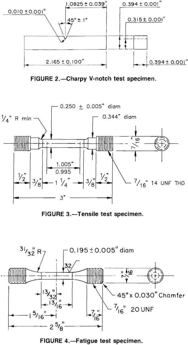
Test blanks were cut from the forged plates and machined into Charpy impact, tensile, and fatigue specimens. Impact specimens were standard Charpy V-notch specimens conforming to American Society for Testing and Materials (ASTM) specification E23-82, type A. Their configuration and dimensions are shown in figure 2. Tensile specimens were proportional to standards, and conformed to ASTM specification E8-83. The configuration and dimensions of the tensile specimens are shown in figure 3. Fatigue specimens were standard, con-forming to ASTM specification E466-82. Their configuration and dimensions are shown in figure 4.
After machining, the specimens were packed in Ti-6Al-4V alloy machine chips in a carbon steel container that was evacuated, backfilled with helium, and sealed by welding in an inert atmosphere. The samples, as contained, were annealed (container was not annealed to remove strain) at 1,300° F (704° C) for 2 h to remove any residual strain. Following the 2-h annealing treatment in an open electric furnace, the container was removed from the furnace and air cooled to room temperature before the specimens were removed.
Test Procedure and Results
Fluoride Inclusions
The metallographic study to identify fluoride anomalies in the microstructure caused by CaF2 flux used in the induction slag melting process was done on a scanning electron microscope (SEM) microprobe and an image analyzer. An attack polishing technique was used to prepare all samples for SEM-microprobe and image analyses. The method employs a 1-µm particle diameter Al2O3 for the initial polish and a 0.05-µm particle diameter Al2O3 with a light acid mist spray on the wheel for the final polish.
Specimens were examined from ingots produced from four separate treatments: (1) single induction-slag melted (S-ISM) only, (2) S-ISM plus single vacuum-arc remelt (S-VAR), (3) S-ISM plus double vacuum-arc remelt (D-VAR), and (4) D-VAR only., Typical data are shown in table 2.
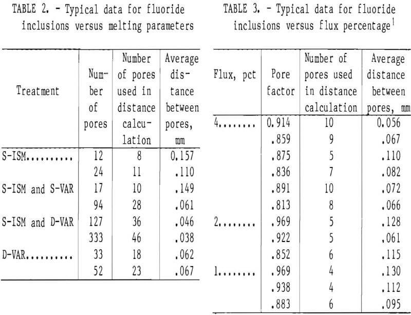
A study was also conducted to determine the effect of reducing the amount of CaF2 flux used during the ingot melting process. S-ISM ingots were produced with the normal 4-pct flux addition and also with 2-pct and 1-pct additions of CaF2 flux. Typical data are shown in table 3.
Mechanical and Fatigue Testing
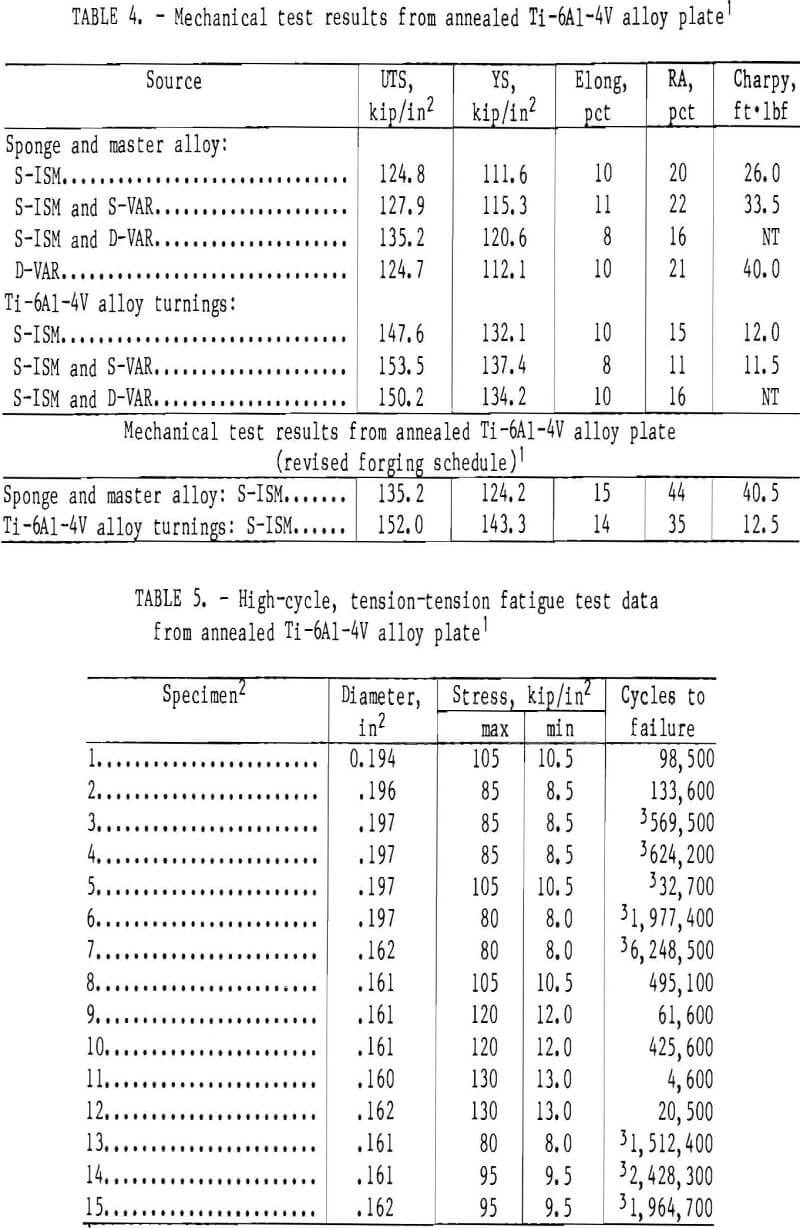
Charpy V-notch specimens were prepared and tested in accordance with ASTM specification E23-82. Tests were performed on a Riehle model R-21314 pendulum C-type machine. The linear velocity of the hammer at the instant of striking was 18.1 ft/s. The temperature of the specimens was 22° C (72° F). The results are shown in table 4.
Tensile specimens were prepared and tested in accordance with ASTM specification E8-83. After inspection, the specimens were gauge marked and placed in the grips of the testing machine, and an extensometer was attached to the specimen and to a stress-strain recorder. The tensile test was performed by loading at a strain rate of 0.005 in/in·min-1 through a specified offset of 0.2 pct. The extensometer was then removed, and the specimen was loaded to failure at a strain rate of 0.05 in/in·min-1. The results are shown in table 4.
The fatigue specimens were prepared and tested in accordance with ASTM specification E466-82. The fatigue tests were performed on a Krouse axial fatigue machine. A sinusoidal tension-tension load program was used in which the maximum tensile stress (Smax) was equal to 60 to 95 pct of the room temperature yield strength. The minimum tensile stress (Smin) applied to the specimen was arbitrarily chosen to equal 10 pct of Smax. The frequency used was 30 Hz. The cycles to failure were automatically recorded. The results are shown in table 5.
Discussion of Results
Fluoride Inclusions
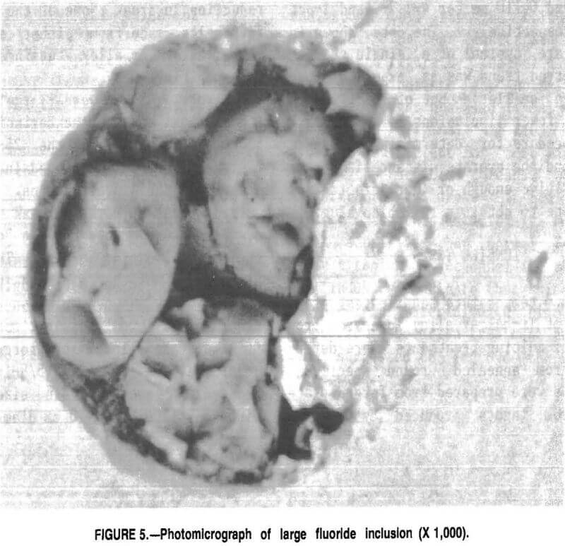
Considerable difficulty was encountered with fluoride pullout during polishing. The pullouts created uncertainty about whether a site was a gas pore or an inclusion that had pulled out during polishing. Figure 5 shows a typical large inclusion and the friable nature of the inclusions. Since each site, whether a pore or an inclusion, represented a possible initiation site for fatigue failure; a new approach for counting the total number of sites in a given area was applied. These analyses were done with an image analysis system. An image was acquired from the SEM and converted into a binary image showing a white background with black inclusions. The image was inverted to a black background with white inclusions, and the distance between inclusions was measured directly on the image. To eliminate operator bias, measurements were made between inclusions on two diagonal lines across the field.
The initial studies showed that fluoride-related anomalies in the microstructure were CaF2 inclusions containing smaller amounts of magnesium and sodium in ingots made from sponge and master alloy. Inclusions in ingots made by remelting Ti-6Al-4V alloy turnings contained only CaF2. The inclusions ranged from 0.0005 to 0.002 mm diam, but some particles of flux as large as 0.035 mm diam were found frozen just under the outside surface of ingots. The density of the pores was approximately 0.5 pet of the total area being examined. The total area examined was 0.089 mm².
Specimens were examined from the four separate treatments, S-ISM, S-ISM and S-VAR, S-ISM and D-VAR, and D-VAR. It was hoped that the vacuum-arc remelts would vaporize the fluoride inclusions from the initial ISM, but, unfortunately, the additional arc melting steps fragmented the inclusions. Thus, the size of the inclusions was decreased, but the number of inclusions was increased
(table 2). No fluoride inclusions were detected by microprobe in the double-arc-melted samples.
The study to determine the effect of reducing the amount of CaF2 flux during the melting process did not provide any conclusive data. Another approach was employed utilizing the image analysis system’s chord function. The system draws 128 evenly spaced, horizontal lines across the field. By setting the maximum length to be included just short of the distance across the field, a chord that did not hit an inclusion was listed as an overflow. Dividing the number of overflow lines by 128 gave a relative index of the pores (the pore factor in table 3) that was completely unbiased by operator judgement. Statistically, there was no significant difference between these data and the data obtained from the study (table 3). Any random sample selected would represent the mean. However, there did appear to be a trend in the number of inclusions measured to determine the average spatial distance between inclusions in an x-y plane. The averages, determined from several samples, were 0.080, 0.102, and 0.110 mm for 4-, 2-, and 1-pct flux, respectively. The data shown in table 3 are typical of a single sample. The observed trend was as expected since use of a smaller amount of flux should produce fewer inclusions. Apparently, the procedure for determining the pore factor and the average distance is either not sensitive enough or there are too few inclusions to obtain a reliable value.
Tensile Tests
The room temperature tensile test properties of Ti-6Al-4V alloy prepared from the four melting treatments were determined from annealed round specimens. Specimens were prepared from forged plate made from ingots produced by melting sponge plus 60:40 Al-V master alloy and remelting Ti-6Al-4V alloy machine turnings. The data in table 4 represent the mean values from four test specimens. The results from a two-tailed t test and a Chi-square (goodness-of-fit) test showed that any random sample selected would represent the mean and that the data fit a normal distribution, respectively, for both sets of data.
An analysis of variance was done to determine if there was a significant difference owing to the four melting treatments (S-ISM, S-ISM and S-VAR, S-ISM and D-VAR, D-VAR). The null hypothesis was that there was no difference owing to the treatments. However, evaluation of the data using an F test and Chi-square test to evaluate (consistency), resulted in rejection of the null hypothesis. In general, the data showed a significant effect, 85 to 90 pct of the variance was due to the melting treatment.
The minimum requirements for titanium alloy bars and forgings as specified in AMS4928H are 130 kips/in² for tensile strength, 120 kips/in² for yield strength, 10 pct elongation, and 25 pct reduction in area. None of the specimens from melts made from either sponge and master alloy or alloy turnings met the AMS specifications.
The poor results were largely due to the physical size of the beginning ingot, 89 mm (3½-in), and the 25-mm (1-in) finished plate size employed in the early stages of the investigation. The required amount of work to break up the as- cast structure could not be applied to the material during forging. The average grain size of the finished plate was 0.80 mm diam. A new specimen configuration was employed for fatigue testing, (fig. 4) that allowed the forging to be continued down to 16 mm (5/8-in). This reduced the average grain size of the finished plate to 0.010 mm diam.
Another set of specimens was prepared from plate forged down from newly melted S-ISM ingot using the revised forging schedule. The values obtained from these test specimens, (table 5) all exceeded the minimum specifications as stated above.
The marked increase in ultimate and yield strength and the decrease in reduction in area, evident from comparison of the data for unalloyed sponge plus 60:40 Al-V master alloy and remelted Ti-6Al-4V alloy turnings, was caused by the interstitial oxygen content of the two materials. The unalloyed sponge has an oxygen content of 500 ppm, and the machine turnings have an oxygen content of 2,000 ppm.
Charpy V-Notch Tests
The average impact strength determined by Charpy V-notch testing of annealed specimens at room temperature ranged from 26.0 ft·lbf to 40.5 ft·lbf for specimens made from ingots of unalloyed sponge and 60:40 Al-V master alloy and from 11.5 to 12.5 ft·lbf for specimens made from ingots of remelted Ti-6Al-4V alloy turnings. A typical value of forged Ti-6Al-4V alloy is 17 ft·lbf. The values for the sponge-plus-master-alloy ingots compare favorably with this figure. The brittle nature of the specimens from the remelted turnings was again due to the amount of interstitial oxygen present in the material.
Fatigue Tests
Room temperature tension-tension high-cycle fatigue tests were conducted on round test specimens with a buttonhead grip configuration. Samples prepared from S-ISM and S-ISM plus S-VAR plate forged down from ingots made from unalloyed sponge plus 60:40 Al-V master alloy were tested at 90, 85, 80, and 75 pct of room temperature yield strength. The scatter in the results obtained was approximately equal to the average value for the data. Again this was because of the size of the starting ingot, 89 mm (3½ in) and the finished forged plate, 25 mm (1-in) thick. The material was not worked enough to break up the as-cast structure, and, therefore, data with a high degree of scatter would be expected.
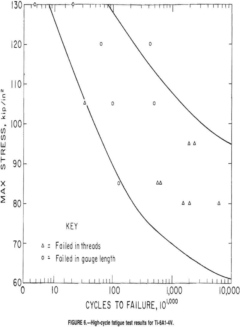
Because of the poor results obtained, additional test specimens were prepared from S-ISM ingot forged down to 15-mm thick (5/8 in) plate using a revised forging schedule (fig- 6). A total of 15 round specimens were sent to an outside testing laboratory for the purpose of generating a stress life (5-h) diagram.
The specimens started failing in the threads, generally after about 500,000 cycles; therefore, the diameter was reduced from 0.195 to 0.160 in. This delayed failures in the threads up to about 2,000,000 cycles. The ratio of thread area to reduced diameter area was about 4:1 for the 0.195-in-diam specimen and about 5.8:1 for the 0.160-in-diam specimen. The test results are shown in table 5 and figure 6. The solid lines in the figure indicate the normal scatter band for wrought annealed Ti-6Al-4V alloy. The original 4:1 area ratio is generally sufficient for most materials, even with machined threads, to give satisfactory failures. It can only be assumed that this material is much more notch sensitive than normal Ti-6Al-4V alloy titanium. Personnel in the titanium industry indicate that this is not untypical for material with high tensile properties. Solution treatment and aging were suggested to improve the fatigue properties.
Conclusions
The work reported here resulted in the conclusions listed below.
- Fluoride-related anomalies in the microstructure of ingots made from unalloyed sponge 60:40 Al-V master alloy were CaF2 inclusions containing smaller amounts of magnesium and sodium.
- Inclusions in ingots made from remelt Ti-6Al-4V machine turnings contained only CaF2.
- First and second vacuum-arc remelts of single-induction-slag-melted ingots fragmented the inclusions, thus decreasing their size and increasing their number.
- Reductions in the amount of CaF2 flux, from 4 down to 2 and 1 pct, resulted in an upward trend in the distance between pores, in an x-y plane for single-induction-slag-melted ingots.
- When adequate work is put into the material during forging, the room temperature tensile properties of single induction-slag-melted Ti-6Al-4V alloy plate exceed the minimum values for titanium alloy bars and forgings as specified in AMS4928H.
- Forged plate produced from single-induction-slag-melted unalloyed sponge plus 60:40 Al-V master alloy is much more notch sensitive than normal Ti-6Al-4V alloy titanium.