
Table of Contents
As part of the goal to maximize minerals and metals recovery from primary domestic resources, design factors associated with minimizing current leakage in bipolar cell configurations were studied by the Bureau of Mines as a means of improving the efficiency of bipolar electrooxidation cells. Initial studies that were conducted in a small bipolar cell operating at 140 to 145 volts and 15.4 amp indicated how design factors could be employed to minimize current leakage around adjacent electrodes during cell operation. Based on these results, a 40-electrode, 108-kva prototype of an industrial-sized cell was constructed and tested for extracting metal values from offgrade molybdenite concentrates. The feasibility of recovering molybdenum and rhenium from the oxidized pulp also was determined. Feed to the process sequence consisted of flotation concentrates containing 16 to 35 pct Mo as molybdenite and 6 to 15 pct Cu. Electrooxidation in the prototype cell resulted in 84 to 97 pct Mo and Re extraction with a corresponding energy consumption of 9 to 13 kwhr/lb Mo extracted.
As part of the effort to improve the Nation’s minerals technology base, the Bureau of Mines investigated a process to extract molybdenum and rhenium from molybdenite concentrates. The process is based on the electrolytic generation of hypochlorite in a brine slurry to oxidize molybdenum disulfide and rhenium sulfide to water soluble molybdate and perrhenate compounds. Molybdenum and rhenium are often recovered as byproducts in the milling of porphyry copper ores; this represents a significant source of molybdenum and the only source of rhenium. However, some copper producers encounter difficulties in making acceptable grades of molybdenite concentrates without suffering a loss of 40 to 50 pct Mo in the flotation sequence.
Some porphyry copper ores contain significant amounts of rhenium, which is intimately associated with molybdenite. Consequently, not only do rhenium losses closely parallel molybdenum losses during concentration by flotation, but additional losses are encountered in the recovery of rhenium by scrubbing the highly volatile rhenium oxide contained in offgases generated during roasting of the molybdenite to molybdic oxide. Finally, roasting of the molybdenite product to obtain molybdic oxide results in formation of sulfur oxide gases, which must be controlled to prevent atmospheric pollution.
Major losses of molybdenum and rhenium occur during flotation in the cleaner flotation sequences; therefore, a process that would accept lower grade, partially cleaned molybdenite flotation concentrates that contained some copper could significantly improve overall molybdenum-rhenium recovery. The Bureau of Mines electrooxidation process will accept a variety of molybdenum concentrates that contain significant amounts of copper as chalcopyrite, and the process has the following potential advantages over present-day practice: Improves molybdenum-rhenium recovery; eliminates generation of sulfur oxide gases; eliminates the need to dry molybdenite concentrates prior to, or during, the roasting step to produce molybdic oxide; and eliminates some of the cleaner flotation steps. Results obtained in small-scale and process demonstration tests involving molybdenite concentrates that contain 35.6 pct Mo, a nominal 20 pct C, and 1 pct Cu have been reported. These studies were conducted in bipolar electrooxidation cells; however, the cells used in these tests were designed without regard to the effect of current leakage around adjacent electrodes.
This report describes a study of methods to minimize current leakage during bipolar cell operation, the design of a prototype industrial-scale electrooxidation cell, and subsequent tests conducted in cooperation with the Nevada Mines Div. of Kennecott Copper Co. to demonstrate the extraction of molybdenum and rhenium from offgrade molybdenite concentrates that contained 6 to 15 pct Cu. Process development studies were conducted only on the electrolysis step; conventional process metallurgy operations, such as solvent extraction, filtration, and crystallization, were employed to recover molybdenum and rhenium from the oxidized reaction pulp.
Electrooxidation Theory & Principles
The basic concept involved in the electrooxidation process is to slurry the concentrate in brine and to electrolyze the resultant pulp to generate hypochlorite ion in situ. The chemical reactions that take place during electrolysis are as follows:
2 Cl – → Cl2 + 2e- (anode)…………………………(1)
and, 2H2O + 2e- → 2 OH- + H2 (cathode)………………….(2)
The chlorine and hydroxyl ion produced in these reactions combine to form hypochlorite ion—
2 OH- + Cl2 → OCl- + H2O + Cl-………………………(3)
The hypochlorite ion reacts, in turn, with molybdenite as follows:
MOS2 + 9 OCl- + 6 OH- → MoO4 2- + 9Cl- + 2SO4 2- + 3H2O…………………(4)
The reaction for the oxidation of rhenium is as follows:
Re2S7 + 28 OCl- + 16 OH- → 2ReO4- + 28 Cl- + 8H2O + 7SO4 2-……………………(5)
The energy required to produce 1 pound of sodium hypochlorite in the concentrate-brine pulp is in the range of 1 to 2 kwhr, thus indicating that the electrooxidation technique has potential economic advantage over the purchase of chlorine and sodium hydroxide as reagents. Both the sodium molybdate and perrhenate compounds that are formed during electrolysis are soluble and can be recovered from solution and processed into marketable products by conventional process metallurgical operations such as solvent extraction, filtration, and crystallization.
Equipment and Operating Procedure
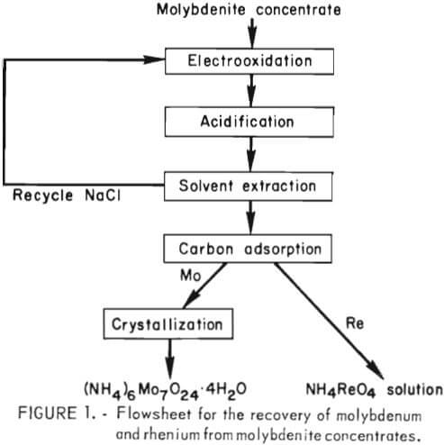 The overall flow sequence for the electrooxidation process is shown in figure 1. Basically the process consists of (1) electrooxidation of the brine-concentrate slurry to produce soluble molybdate and perrhenate ions, (2) liquid-solid separation, (3) treatment of the clarified pregnant solution with sulfur dioxide to lower the pH and reduce the chlorate ion to chloride ion, (4) recovery of salt and concentration of molybdenum-rhenium by solvent extraction with a tertiary amine, (5) selective absorption of rhenium on activated carbon, (6) stripping of rhenium from the activated carbon and recovery of the rhenium as NH4ReO4, (7) recovery of molybdenum as molybdic oxide by crystallization followed by roasting, and (8) removal of sulfate ion from recycle brine by crystallization.
The operating procedure for testing the 108-kva prototype electrooxidation cell on a batch basis consisted of mixing a predetermined amount of concentrate with 750 gal of water and 700 pounds of sodium chloride in a stirred vessel. The pulp density of the 10 wt-pct brine-concentrate slurry used in this study ranged from 3 to 15 pct. The pulp was pumped from a stirred vessel through the bipolar cell at 200 gal/min and returned to the same vessel by gravity flow. The cell was operated at 900 amp and 120 volts with a current density of 0.38 amp/in². Temperature was maintained at 45° to 50° C in the electrooxidation system by heat exchange. During treatment, the pH was maintained between 5.5 and 7.0 by adding sodium carbonate. The electrooxidation treatment, required 8 to 18 hours, depending upon the amount of molybdenum contained in the concentrate initially added to the system. Molybdenum and rhenium extractions were determined by conventional analytical techniques.
Bipolar Cell Development
 Early studies to evaluate the electrolytic oxidation concept were conducted in simple monopolar cells that operated at 3 to 3.5 volts. Scale-up of the laboratory monopolar cell to an industrial-scale operation presented serious problems; the high amperage-low voltage rectifiers and attendant large-sized bus bars needed are costly and, because of their bulk, present design and operating difficulties. One method of overcoming these disadvantages is to use a bipolar cell. In a monopolar system, the anodes and cathodes are connected in parallel, and each electrode must be attached to the corresponding bus bar. In a bipolar system, only the two end electrodes are connected to the direct current source with intermediate electrodes having no direct electrical connection to the bus bars. During electrolysis, the intermediate electrodes become bipolar and assume opposite charges on either side. Each adjacent pair of electrodes acts as an individual cell in series with any other adjacent pair. As a result of this configuration, the voltage and rate of hypochlorite production is increased roughly n-1 times the number of electrodes as compared with the monopolar arrangement. A bipolar system requires a higher voltage but a correspondingly lower amperage than a monopolar cell system. The net result saves space, minimizes the size of bus bars, and simplifies rectifier needs.
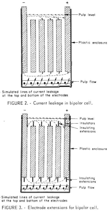
Ideally, in the operation of a bipolar cell, current passes from the end electrode through each intermediate electrode in sequence. However, if a low resistance pathway exists between nonadjacent electrodes, a portion of the current will bypass adjacent electrodes (dashed lines fig. 2) and result in a reduction in current efficiency. Current leakage around the sides of the electrodes was minimized effectively by inserting both edges of each electrode into a 0.5-inch recess in the cell container walls; this eliminated the solution path at the sides of the electrodes that provides a current leakage. However, current leakage around the top and bottom ends of the electrodes is a more formidable problem because both the upper and lower ends of the electrode system must be open to permit pulp flow. A study was conducted to determine the feasibility of increasing the leakage current path at each end by placing nonconductive extensions on both the top and bottom of each electrode (fig. 3). A comparison of figures 2 and 3 shows that by placing nonconductive extensions on the ends of each electrode, the length that the current must travel between nonadjacent electrodes is increased. Increasing the current path results
in a corresponding increase in electrical resistance through the slurry, and if the current path is made sufficiently long, current leakage in the cell will be negligible. The small test cell used in this investigation consisted of 46 electrodes, 48 inches long, ¾ inch wide, and ¾ inch thick. The electrodes were enclosed in a nonconducting box and were separated by 5/16-inch spaces. The electrodes were positioned initially 3-¼ inches above the slurry delivery pipe at the bottom of the cell and extended 7 inches above the top of the box. Provision was made in the cell design to allow the electrode configuration to be altered by removing that portion of the electrodes that extended above the top of the box and adding various lengths of nonconducting extensions to the top and bottom of the electrodes.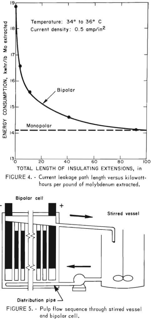
The cell was operated at 135 to 145 volts and 15.3 amp, which corresponds to a current density of 0.5 amp/in². To test the efficiency of the cell, an offgrade molybdenum concentrate was treated while various lengths of insulation were added onto each end of each electrode. Baseline experiments were conducted to determine the efficiency of the cell before modification. Under these conditions, energy consumption was 18.9 kwhr/lb Mo extracted. The cell was then modified by placing 3-inch plastic inserts at the bottom of all electrodes, and cell efficiency increased by 12.7 pct when the same offgrade molybdenum concentrate was treated in the cell. The cell was again modified by shortening the intermediate electrodes to 2 inches below the pulp level, and then placing a 3-inch-high block of acrylic plastic on top of each electrode. The acrylic block extended 1 inch above and 2 inches below the pulp level, thus increasing the length of the leakage path between nonadjacent electrodes. This increased the efficiency for treating the molybdenite concentrate in the cell by another 2 pct. The cell was modified again by increasing the insulation on the bottom of each 48-inch-long electrode to 23 inches. The energy consumption with 2 inches of insulation on the tops of the electrodes and 23 inches on the bottoms was 14.6 kwhr/lb Mo extracted. Figure 4 shows the effect of insulating the electrodes to increase the length of the current leakage path between nonadjacent electrodes versus energy consumption per pound of molybdenum extracted. Compared with the baseline experiment in which an energy consumption of 18.9 kwhr/lb Mo extracted was obtained, the overall increase in efficiency obtained by insulating the ends of the electrodes was 22.8 pct. Based on these data, a prototype bipolar cell that incorporated the concept of using insulation to increase the current leakage path between nonadjacent electrodes was designed and constructed for larger scale experiments on offgrade molybdenite concentrates.
A schematic of the prototype cell system employed in larger scale tests is shown in figure 5. This 108-kva bipolar cell consisted of 41 graphite electrodes, 48 inches wide and 50 inches high with 5/16-inch electrode gaps. The two end electrodes were 2 inches thick, and the 39 intermediate electrodes were 0.81 inch in thickness. The overall cell dimensions were 4 feet by 4 feet by 7 feet high. Electrical connections were made only to the two end electrodes, and each of the intermediate electrodes functioned as both anode and cathode on opposite sides. Twelve-inch plastic extensions were placed on both ends of each intermediate electrode to minimize current leakage in the cell. The pulp was pumped from the stirred vessel up between the electrodes in the cell and overflowed back to the vessel by gravity (fig. 5). Uniform distribution of pulp in the bottom of the cell was achieved by providing eight distribution pipes, each containing twenty 9/32-inch perforations. (A photograph of the cell and stirred vessel is shown in figure 6). The cell has a theoretical capacity of generating 110 pounds of sodium hypochlorite per hour, which could in turn react with 26.2 pounds molybdenite.
Large-Scale Electrooxidation Tests
A total of 13,000 pounds of molybdenite concentrates of varying compositions was treated in a 10-week experimental campaign at Kennecott’s Nevada Mines Div. at McGill, Nev., using the prototype cell. The concentrates also contained 6 to 15 pct Cu as mixed chalcocite and chalcopyrite minerals.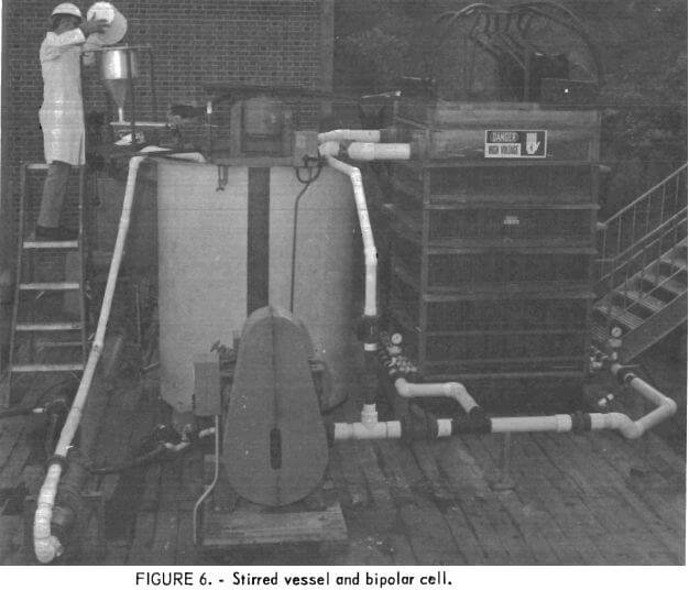
Molybdenum-rhenium extractions of 93 to 97 pct were typically obtained from concentrates that contained a nominal 7 pct Cu, but molybdenum extraction decreased with increasing copper concentration. Only 75 pct of the molybdenum was extracted when the concentrate contained 15 pct Cu. Examination of the electrooxidation tailings revealed the presence of copper molybdate compounds. These results are consistent with previous laboratory-scale experiments that had indicated that chalcopyrite mineralization contained in the molybdenite was not affected during electrolysis, whereas the presence of chalcocite was detrimental because it was partially oxidized to form small amounts of soluble copper compounds that could react with the molybdate ion to form insoluble copper molybdate.
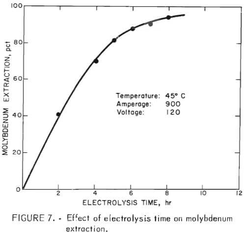 Energy consumption during electrolysis varied between 10 and 13 kwhr/lb Mo extracted, depending on the mineralization and copper content of the concentrate. Figure 7 shows typical results obtained in tests made to determine the effect of energy input (or time of electrolysis) on molybdenum extraction.
Constant operating conditions of 900 amp, 120 dc volts, and 45° C were maintained in the tests. The concentrate used in these particular tests contained 34 pct Mo and 7 pct Cu. The data show that molybdenum extraction increases almost linearly with time until an extraction of about 80 pct is reached; then it starts to level off. A molybdenum extraction of 95 pct was achieved after treating for 8 hours; copper extraction from this concentrate was less than 0.1 pct. Total energy input into the system was 10 kwhr/lb of contained molybdenum after 8 hours of electrolysis. Energy consumption per pound of molybdenum extracted was 7.7 kwhr after 5 hours electrolysis and increased to an overall energy consumption of 10 kwhr after 8 hours.
During the testing of this prototype cell, maintenance was not required and the cell was operated virtually unattended. Disassembly of the cell after the tests showed that electrode wear was negligible.
Molybdenum and Rhenium Recovery
Figure 8 details the process sequence employed for recovering molybdenum and rhenium from the electrooxidation reaction pulp. Liquid-solids separation was accomplished in two 3-foot rake thickeners in series with a 1- by 3-foot washing rotary drum filter. The pregnant solution was clarified in a 1- by 1-foot plate and frame filter press. The resulting clarified solution then was pumped to a stirred vessel and treated with sulfur dioxide to lower the pH from 6 to approximately 1. This treatment also destroyed simultaneously any chlorate that may have been generated during the electrooxidation step. The acidified pregnant solution was fed to a solvent extraction unit at the rate of 1 gal/min. The organic extractant consisted of a mixture of 7 vol-pct tertiary amine (Alamine 336) and 7 vol-pct decyl alcohol dissolved in Socal 355L solvent. The extraction step was carried out in three stages (fig. 8). Stripping was accomplished in two stages using 1.7N ammonium hydroxide. The concentration of molybdenum and rhenium entering the solvent extraction circuit was 12 to 18 g/l molybdenum and 25 to 40 ppm rhenium. The strip solution contained 101 to 108 g/l molybdenum and 200 to 410 ppm rhenium as ammonium molybdate and ammonium perrhenate, respectively. The raffinate contained 0.05 to 0.09 g/l molybdenum and 1 ppm rhenium.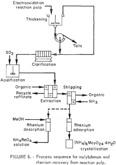
As shown in figure 8, the strip solution flowed through a column of activated carbon where rhenium was preferentially absorbed on the carbon.
Typically, solutions containing 200 to 410 ppm rhenium entering the carbon absorption column exited the column at a concentration of 1 ppm rhenium. Although not demonstrated during these experiments, a procedure has been devised for stripping rhenium from the activated carbon with a 75 vol-pct methanol-25 vol-pct water solution. Rhenium is stripped from the carbon with 1 bed volume of stripping solution. Methanol may be recovered from the rhenium strip solution by distillation and then recycled to the stripping system- The distillation raffinate usually contains up to 40 g/l rhenium, up to 240 ppm molybdenum, and 3 to 5 g/l chloride ion. Rhenium can be recovered from this solution by ion exchange, and ammonium perrhenate of 99+ pct purity can be obtained.
Molybdenum was recovered from the carbon column effluent solution by crystallization of ammonium paramolybdate. Crystallization was carried out on a batch basis at atmospheric pressure in 55-gal heated vessels. Under these conditions, the initial crop of crystals analyzed 99 pct ammonium paramolybdate after washing with water. Detailed information on the crystallization of ammonium paramolybdate was reported previously.
Conclusions
Current leakage losses that occur in operation of bipolar flow-through electrooxidation cells can be minimized by incorporating cell design factors that increase the current leakage path by sealing the edges of the electrodes in the sides of the cell enclosure and adding nonconductive extensions on the top and bottom of each electrode.
Operability of the bipolar cell for treating offgrade molybdenite concen-trates was demonstrated in a prototype cell. Overall molybdenum and rhenium recoveries of 97 pet can be obtained from flotation concentrates that contained 16 to 35 pet molybdenum. Molybdenum-rhenium extraction was unaffected by presence of chalcopyrite in the molybdenite concentrate; however, molybdenum extraction declines if the copper content, as chalcocite, exceeds 7 pct. High-purity molybdenum and rhenium compounds can be recovered from the electrolyzed reaction mass by liquid-solid separation, solvent extraction, and crystallization steps.