
Table of Contents
The U.S. Bureau of Mines developed an alternative electrochemical process for the production of calcium metal. The current industrial practice is costly, complex, and inefficient. The Bureau method involved electrowinning of a calcium-tin alloy followed by electrorefining to produce calcium metal. In the electrowinning cell, CaCl2 was fed to a KCl2-CaCl2 electrolyte. The calcium was electrowon at 650° C into the pure molten tin cathode until the cathode contained 7.5 wt pct Ca. Current efficiency for electrowinning averaged over 90 pct. The resulting calcium-tin alloy served as the anode for the electrorefining cell, which employed a CaCl2-CaF2 fused salt as the electrolyte. Calcium metal was electrorefined at 850° C with a current efficiency of 85 pct based on calcium metal recovered. The calcium metal analyzed 99.2 pct, which is purer than commercially produced calcium.
The U.S. Bureau of Mines has investigated the electrolytic production of calcium metal. The procedure has low energy requirements and may lower the cost of producing calcium. Lower cost calcium metal would promote wider use.
Before adoption of the present commercial process, calcium metal was manufactured by the direct electrolysis of CaCl2. In this batch process, a “carrot” of solid calcium was electrowon that contained a large amount of occluded salt. The process was difficult to control and operated at only 60-pct current efficiency. Aluminothermic reduction of lime to produce calcium metal, which was commercialized in the 1940’s, is the only process currently used for calcium production in the United States. Calcium oxide and aluminum powder were briquetted and then retorted at 1,200° C under vacuum. Purity of the calcium metal was 98.8 pct, and the purity could be improved to 99.5 pct by redistillation. The major impurity of the redistilled calcium was magnesium at 0.5 wt pct. High-energy consumption and a labor intensive batch operation were disadvantages of the process. Moreover, powdered aluminum metal was an expensive reductant, and aluminum utilization was only about 60 pct.
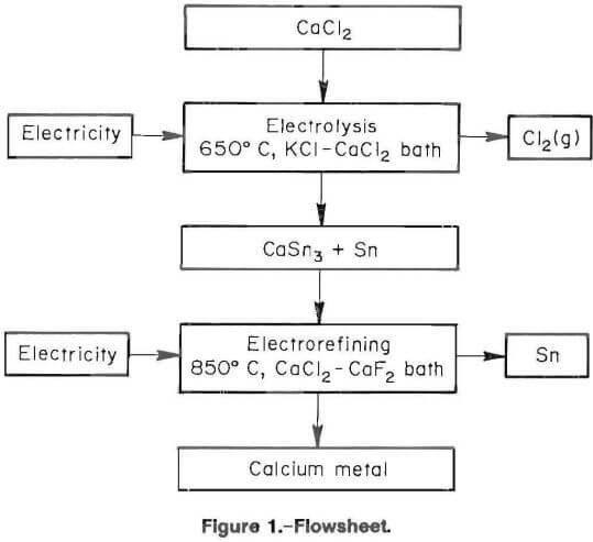
The proposed electrochemical process depicted in figure 1 was simple, energy efficient, and could be made continuous. Calcium chloride was fed to the electrowinning cell, which had a molten tin cathode. The electrowinning cell produced calcium-tin alloy and byproduct Cl2. After electrowinning calcium into the tin cathode, the calcium-tin alloy became the anode for the electrorefining cell. Calcium metal analyzing 99.2 pct pure was recovered from the electrorefining cell.
Equipment and Materials
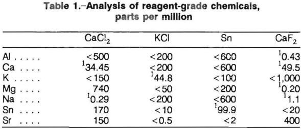
Analysis of the reagent grade chemicals employed in the electrowinning-electrorefining tests is shown in table 1. The salts were dried in an oven and stored in a desiccator prior to use. Before electrolysis, the tin cathodes and electrolytes were melted in graphite crucibles with induction heating.
A proportioning controller and wire wound resistance furnace maintained the electrolytic cell at the desired temperature for all experiments. Type K inconel-clad thermocouples encased in alumina sheaths were used to monitor temperature. A Hewlett Packard 6264B rectifier provided electric current for electrolysis. A Curtis model 1002 integrator was used to measure electrolysis current, and a Fluke model 8026B multimeter was used to monitor electrolysis voltage.
Figure 2 depicts the electrowinning cell. A 250-mL alumina crucible served as the cell container. One- hundred-twenty grams of pure tin was placed on the bottom of the crucible to serve as the cathode. The salt charge containing 170 g of well mixed chlorides (75 mol pct KCl-25 mol pct CaCl2) was added to the crucible. The thermocouple assembly was placed into the powdered salt. When the salt became molten, the cathode current feeder and anode assemblies were positioned. The cathode current feeder was a 0.6-cm-diam by 30.5-cm-long tungsten rod, which was encompassed by a 1.8-cm-ID open-ended alumina sheath. The anode assembly consisted of a 0.6- cm-diam by 30.5-cm-long graphite rod, which was inserted into the middle of a 1.8-cm-ID alumina sheath and submerged 2.5 cm into the molten-salt electrolyte. The open-ended alumina tube served as an anode sheath, which vented chlorine gas and prevented both oxidation of the graphite rod and backreaction of the calcium in the cell. Chlorine gas was insoluble in the molten-salt electrolyte and did not affect electrolysis. Upon completion of electrowinning, all the components were removed and the metal cathode and electrolyte were poured into a graphite mold. After cooling, the tin alloy button was separated from the electrolyte.
The electrorefining cell is shown in figure 3. The apparatus was housed in a glove box to prevent oxidation of the calcium metal at the cathode. The glove box was evacuated to approximately 100 µm and backfilled with 99.995 pct pure argon that had been passed through a Drierite desiccant column and an oxygen getter assembly. The getter assembly consisted of a 2-cm-ID by 33-cm-long Vycor pipe filled with minus 4 plus 40 mesh titanium sponge, which was heated to 850° C in a tube furnace.
The calcium-tin cathode alloy from the electrowinning step was placed at the bottom of a 250-mL alumina crucible. An alumina sheathed 1.5-mm-diam thermocouple and an alumina sheathed 3-mm-diam stainless steel rod were placed between a 4-cm-diam by 5-cm-tall molybdenum foil liner and the crucible wall. The stainless steel rod served as the anode bus and was positioned to ensure electrical contact with the calcium-tin alloy anode. The bottom of the thermocouple sheath was positioned 2 cm below the electrolyte surface. The bottom of the foil liner was approximately 1 to 2 cm above the salt-alloy interface. The molybdenum foil liner contained the calcium metal that floated during production and prevented attack on the alumina. One-hundred-seventy grams of electrolyte (52 mol pct CaCl2-48 mol pct CaF2) was placed on the alloy. Once the electrolyte was molten, a 6-mm-diam tungsten rod, which served as the cathode, was immersed 1 cm into the molten-salt bath.

Experimental Procedure and Results
Electrowinning
The results of preliminary tests dictated the parameters of the electrowinning operation. Several pure metals, including cadmium, lead, tin, and zinc, were tried as liquid cathodes. Tin had the highest calcium loading. Several runs were performed to identify acceptable ranges for temperature, voltage, and current density. Different molten-salt baths composed of CaCl2, and one or more of KCl, LiCl, BaCl2 and SrCl2 were tested as electrolytes. Lithium, barium, and strontium were electrowon with calcium into the cathode. As a result, only the KCl-CaCl2 bath was suitable. Feeding CaCl2 at approximately the same rate that decomposition occurred provided for steady operation and prevented freezing of the molten-salt bath.
Electrolysis was initiated as soon as the temperature reached 650° C. The applied current was adjusted to 8 A (0.4 A/cm² cathode current density), and the voltage monitored to determine if the cell was shorted or if the circuit was open. The rectifier was controlled in a constant current mode, and output voltage was limited to 16 V. Electrowinning started at approximately 2.7 V. Ammonia gas was passed over the anode vent to verify electrolysis by forming white NH4Cl. Once steady operation was obtained, the stoichiometrically required amount of CaCl2 was fed to the cell to replace electrolyte depleted during electrowinning. This semicontinuous feeding provided for very smooth operation with little voltage fluctuation. Each test was continuously monitored and operating data were recorded. Immediately after terminating a test, the apparatus was disassembled and the contents of the crucible were poured into a conical graphite mold. After cooling, the tin alloy button could be easily separated from the salt phase. Examination of the apparatus showed there was no corrosion or chemical attack. Table 2 shows typical electrowinning data.
An investigation of operating parameters was undertaken to determine optimum conditions and to model cell characteristics. Temperature, current density, calcium loading, and cathode additives were examined to evaluate their effect on current efficiency (CE).
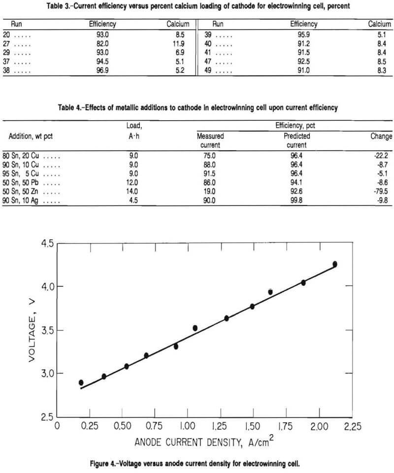
Figure 4 depicts the relationship between anode current density and cell voltage for a 0.6-cm-diam graphite rod anode. The voltage was measured from the tops of the anode and cathode. The cell was operated at 650° C with standard conditions. The graphite anode was immersed 2.5 cm into the molten-salt bath. When the data were projected to 0 A, the decomposition voltage was approximately 2.7 V. This voltage was lower than the theoretical decomposition voltage for CaCl2 at 650° C, which was 3.45 V because of the exothermic reaction in forming the compound, CaSn3.

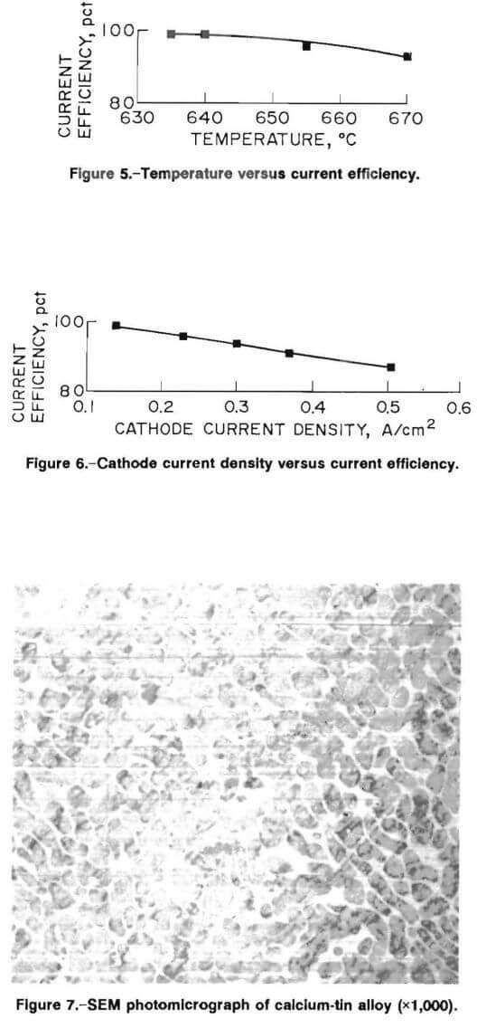
The effect of cell temperature on current efficiency is shown in figure 5. The electrowinning tests, which were run for 16 A · h (approximately 5.6 pct Ca loading), show that current efficiency decreases linearly with increasing temperature. The lowest possible operating temperature was 635° C. Below 635° C, additions of CaCl2 would initiate localized freezing and upset operation of the cell.
Current efficiency decreased with calcium loading of the cathode. Table 3 relates current efficiency and calcium loading in percent calcium. Current efficiency was decreased because the calcium activity in the cathode was increased, and the melting point of the alloy was increased causing viscosity and surface tension of the cathode to increase. The increased viscosity and surface tension impeded the transfer of the calcium metal into the tin cathode.
Current efficiency decreased linearly with increasing cathode current density as shown in figure 6. The cell was operated at 655° C for 9 A · h (approximately 5.1 pct Ca) for these experiments. Increasing cathodic current density caused calcium to buildup at the cathode surface.
The data in table 4 show that the addition of copper, lead, zinc, and silver metals to the tin cathode decreased the current efficiency. The conditions for these experiments were the same as for the experiments with the tin cathode. The purpose of adding metals was to increase calcium solubility, to reduce tin content by partial substitution of a cheaper metal, and to improve loading and current efficiency. The predicted efficiency was the average efficiency that was obtained with a pure tin cathode. The addition of another metal to the tin cathode decreased the current efficiency.
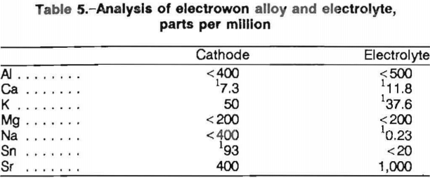
Figure 7 is a scanning electron microscope (SEM) photomicrograph of the calcium-tin alloy. CaSn3 was the predominant species with trace amounts of CaSn. The CaSn3 grains can easily be seen in the tin matrix. An X-ray diffraction analysis of the cathode indicated major CaSn3 and minor tin. The electrolyte was determined to be KCl and KCaCl3 by X-ray diffraction. Table 5 shows an analysis of the electrolyte and the calcium-tin cathode.
Electrorefining
The electrorefining cell was initially used in air with an argon gas blanket, but excessive oxidation of calcium at the melt surface resulted. Subsequent electrorefining was done in a glove box with an argon atmosphere, which permitted visual examination and adjustments during cell operation.
Table 2 summarizes typical electrorefining data. A CaCl2-CaFl2 (52-48 mol pct) electrolyte was determined to be satisfactory. Other electrolytes tested included mixtures of LiF, BaF2, CaCl2, CaF2, and BaCl2. Because calcium reduced these salts in the cell, significant metallic contamination of the product occurred. The CaCl2-CaF2 electrolyte melted at 800° C, was fluid, exhibited 2 pct Ca solubility, and had no detectable tin solubility.
The cell was operated at 850° C to ensure that the calcium product was molten. Higher temperatures would have increased calcium volatilization and calcium solubility in the electrolyte. Cell voltage was adjusted to a maximum of 2 V to prevent electrolysis of the CaCl2. The anode current density at 0.2 A/cm² was near the operating level in aluminum and magnesium molten-salt electrorefining cells, which ranges from 0.3 to 0.8 A/cm².
Periodic inspection of the cell during electrorefining revealed that calcium was oxidizing at the electrolyte surface. A major oxygen source was probably outgassing of the furnace refractories. After the initial adjustment of the rectifier, fluctuations of output voltage and applied current were small. Fuming of the electrolyte was not visible. After the desired ampere hour was reached, heating was terminated and the cell contents froze within 5 min. The voltage was maintained to provide cathodic protection, which prevented dissolution of calcium metal at the cathode. Once the electrolyte was frozen, it could be easily separated from the calcium deposit that was free of occluded salt. The electrolyte remained clean and white and exhibited a sharp interface with the calcium-tin anode.
The calcium product was analyzed as soon as possible to limit oxidation. The apparatus showed no signs of chemical attack or corrosion upon disassembly.
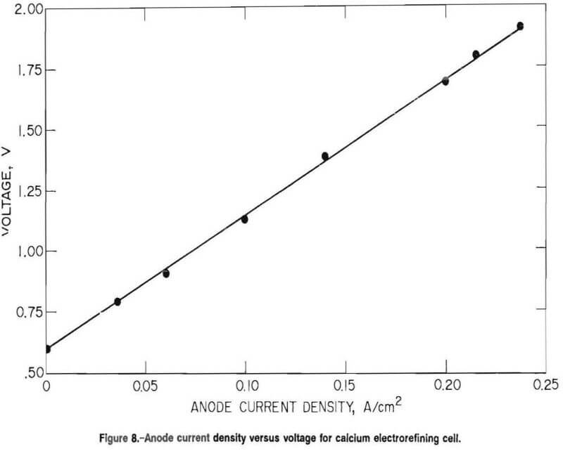
A plot of anode current density versus cell voltage is depicted in figure 8. A potential of 0.6 V was required before electrorefining would proceed.
Several tests were performed to examine the influence of cell parameters on current efficiency and product purity. Electrorefining experiments ranged between 30 and 190 min. Current densities were varied from 0.07 to 0.29 and fiom 0.58 to 2.52 A/cm² for the anode and cathode, respectively. Calcium loading of the anode feed ranged between 4.9 and 9.2 wt pct with an average of 7.36 wt pct. Removal of calcium from the anode varied from 40 to 70 pct in these experiments. Within the above tested ranges, varying the parameters had no discernible effect on purity or current efficiency.
The measured current efficiencies, which were based on calcium recovery, ranged from 75 to 88 pct and averaged only 85 pct. Normally, electrorefining operated at very high current efficiencies. However, when the calcium metal floated on the electrolyte, there was significant oxidation and some evaporation. Also, calcium was 2 wt pct soluble in the electrolyte, and the solubility limit must be reached before the solubility loss was zero. In short duration tests, the solubility loss was significant, but it was not taken into account.
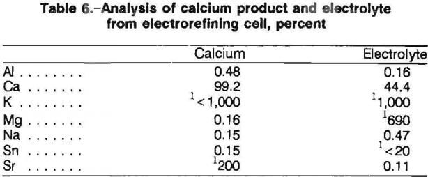
Typical analysis of the calcium metal product and spent electrolyte is found in table 6. Examination of the calcium metal by SEM showed one continuous phase of calcium. Thus, impurities in the calcium did not form separate phases and could not be seen by SEM. According to inductively coupled plasma and atomic absorption analysis, approximately 0.15 wt pct Sn transferred during electrorefining. SEM inspection of the calcium found tin contamination to be uniform. The tin analyzed less than 20 ppm (detection limit) throughout the electrolyte. The calcium could be distilled to remove the tin if desired. Other impurities found in the calcium metal were aluminum, sodium, and magnesium. The impurities were present in the electrolyte reagents and reported to the calcium product. Thus, eventually a purer product would be obtained because the electrorefining operation removed the impurity metals from the electrolyte. After sustained operation with clean feed, the recovery of a high-purity calcium metal product should be possible.
Proposed Electrorefining Cell
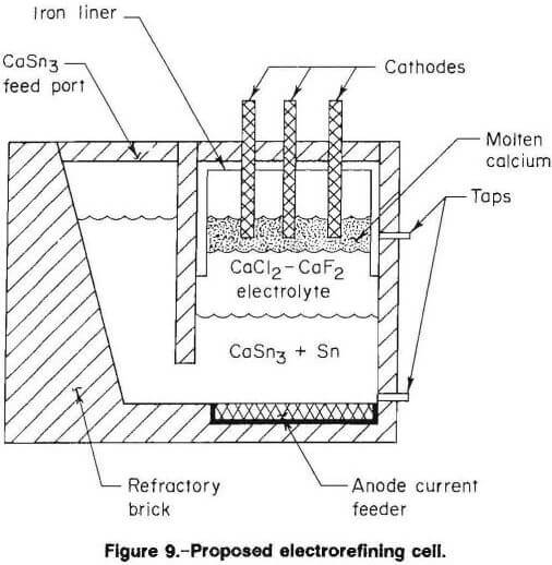
Figure 9 is a schematic of a proposed electrorefining cell for the large-scale, continuous production of calcium. The cell would have an alumina or other refractory liner to contain the calciumtin alloy feed and electrolyte. Steel proved to be suitable for electrodes and lining where calcium metal may be contacted. The levels of CaSn3, electrolyte, and calcium metal would be controlled by monitoring feed and tapping flows. An inert atmosphere above the molten calcium would be required. Cell voltage, temperature, and anode current density should be similar to those of the electrorefining cell in present work.
Summary and Conclusions
The two-step electrochemical process for the production of calcium metal was a simple and efficient method. The first step entailed controlled feeding of CaCl2 to a KCl-CaCl2 molten-salt electrochemical cell. The cell was operated at 650° C. The molten tin cathode was loaded to 7.5 wt pct (18.7 mol pct) Ca. The calcium-tin alloy cathode from electrowinning served as the anode for the electrorefining cell. Calcium metal was collected at the cathode on the surface of the CaCl2-CaF2 electrolyte at 850° C. The recovered product analyzed 99.2 wt pct Ca. The electrowinning cell should be easily scaled up. On the other hand, the electrorefining cell needs further development to determine what current efficiency can be expected and what recovery problems will be encountered in handling molten calcium metal, in scale-up, and in longer term cell operation.