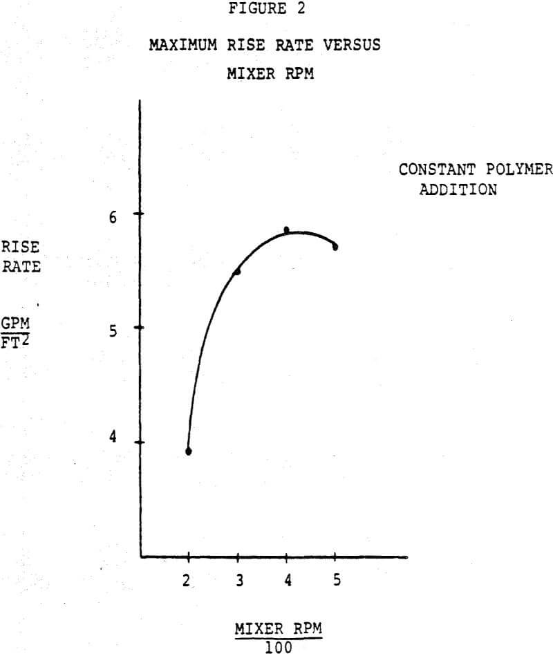
Conventional practice is to add flocculant as a dilute solution to the feed slurry in a launder or feed pipe, possibly using staged addition so as to improve the floc growth. Mixing in launders is not necessarily optimum, and with deep launder pulp depths lower layers of slurry do not readily rise to the surface and become contacted with reagent. Baffles, ridges, and other static mixing devices, might be utilized in a launder to improve this mixing action, but these can create excessive shear or simply not provide uniform mixing conditions. To offset this, additional reagent must be added beyond that which would be predicted from a simple batch test.
The transition from feed launder to feedwell often presents several problems. Feedwells may be attached to the thickener rakes and if a lifting device is employed, sufficient clearance must be allowed between the bottom of the launder and the top of the feedwell in its raised position. This means that the entering slurry must not only be slowed down in its horizontal path, but lowered to the feedwell surface without increasing its velocity. This requires some sort of restriction, such as a valve, which in turn produces the shear which may destroy the floe that has been formed.
Although clarity from this sort of operation is significantly better than it would be otherwise, this system is a delicate balance of the settling rate of the flocculated solids and the up-flow rate of the entrained water. Slight changes in the up-flow rate or degree of flocculation can expand this sludge blanket to the point where it will overflow the clarifier. Thus, careful control is needed and automatic sensing devices may be used to locate the sludge blanket level, with appropriate steps then taken to maintain its position relatively constant. The alternative approach is to keep the blanket below the feedwell outlet, accepting a loss in overflow clarity and relying on extra flocculation or subsequent filtration of this effluent to obtain the intended clarity requirements.
Pilot plant experiments which were conducted in plastic vessels employing this concept demonstrated a significant advantage to the flocculated slurry entering beneath the pulp level, the so-called “sludge blanket” operation described earlier. As expected, turbulence in the clear zone with resultant loss of fine particles in the overflow was greatly reduced as soon as the feed outlet was submerged beneath the pulp level. Although active turbulence was visible in this zone, liquid flow leaving the pulp surface appeared to be uniform across the entire area and the overflow was relatively free of fine solids.
Control of the depth of this bed can be achieved by either changing the underflow rate or changing the flocculant dosage. Sensors are used to locate the position of the pulp level and to transmit signals to actuate controllers which maintain the level within a desired range.
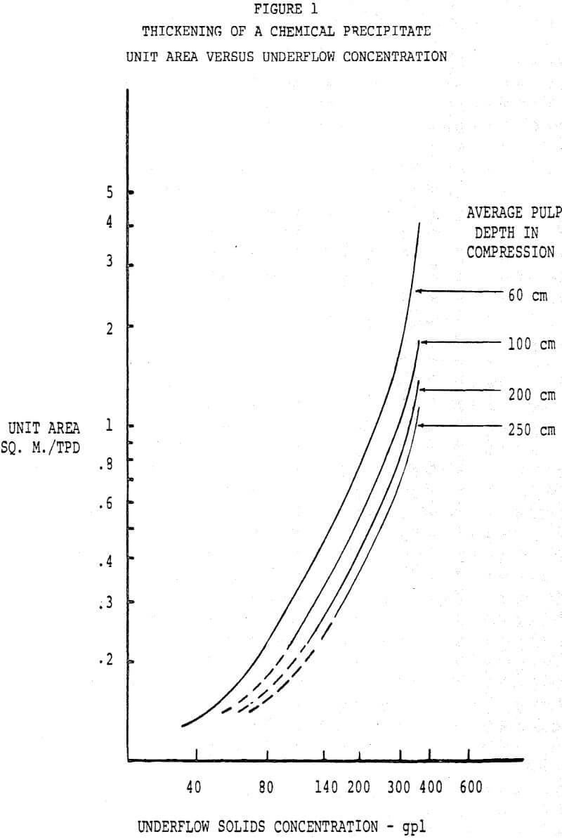
In thickening practice, capacity is usually expressed in terms of thickener cross-sectional area per unit weight of solids per day. Properly, the unit area is shown as a function of underflow solids concentration, and a logarithmic plot exhibits a nearly linear “operating line” which gradually approaches a vertical slope near ultimate density. As shown in Figure 1, with flocculant dosage constant, different operating lines will be found for varying pulp depths, representing decreasing unit area for increasing depth. This relationship is not unexpected. If it is assumed that the increased depth represents additional compression zone volume (or detention time in this zone), then greater capacity should result.
A high dilution of the flocculant was found to be unnecessary, due, apparently, to the rapid rate of blending with the slurry. Reagent concentrations of 0.1 to 0.25% were normal, and in some cases, using water emulsion reagents, solution concentrations as high as 5% could be used.
Flocculant use was comparable in most cases to that which was employed in conventional thickeners operating at a much lower throughput per unit area. Reagent consumption was consistent with that predicted from bench scale cylinder tests conducted under ideal laboratory conditions.
The benefit from the inclined plates proved to be mainly in the dampening of solids feed rate fluctuations. As long as the level was maintained within a zone extending from just below the top of the plates to a point approximately in the center, excellent control was possible using a single ultrasonic sensor sending an on-off signal to a diaphragm pump. In one experiment, the plates were removed during the operation. Subsequently, the bed expanded, indicating that the average solids concentration in this zone is higher with the plates present. Also, a loss in clarity at the same flow rate was experienced when plates were removed.
An increase in underflow density which could be attributed to the action of the inclined plates was observed in some applications, and not in others. Some semi-compacted materials, as discharged from the bottom of the plates, appeared to be more readily redispersed by the entering feed, such that no gain in thickening was achieved.
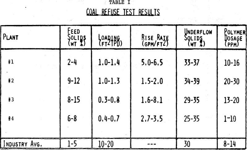
Iron ore concentrate was selected as the first application. Feed to the Hi-Capacity Thickener consisted of hematite iron ore concentrate from flotation cells with a size distribution of 92 – 95% minus 325 mesh. The unit was operated by plant personnel for a five month period, demonstrating that the control strategy could function properly and unattended.
Testing was also conducted on an acid soluble precipitate formed by lime addition and aeration of the acid water found in a uranium process. The material was a typical tvpe gelatinous metal hydroxide, difficult to concentrate. Again, the automated unit demonstrated that the control system could be used by plant personnel without requiring close operator attention.
Performance of the HCT, from an operational and mechanical standpoint, was as expected. No build-up on the inclined plates occurred in any of the tests. The sludge level control system worked very reliably with the ultrasonic sludge level detection device. The torque limit on the rake drive was not exceeded even under the most adverse conditions.