
Belt conveyors used to transport minerals are to be found all around the world in a large number of surface and underground mining operations. The idea of using the conveyor belt is not new, indeed, the first bell conveyors were introduced at the end of the nineteenth century; the basic principles of operation have not changed. However, over the years the capacity rating of belt systems and the length over which material can be transported have increased very considerably, together with the power inputs, the size of components, and the degree of sophistication.
The ‘Rules of Thumb’ set out by McIntosh Engineering underline the advantage of belt conveying across the spectrum of operations. They state:
- An underground mine is more economically served by a belt conveyor than railcars or trucks when the daily mine production exceeds 5000 tons.
- As a rule, belt conveyor operation is more economical than truck haulage if the conveying distance exceeds I km
- A further attempt to provide guidelines for the selection of forms of haulage on cost grounds can be found in the Conveyor Equipment Manufacturers Association (CEMA) publication. CEMA agrees with the second bullet point above and adds four other economic points.
- Beyond 1 km distance, the ton-mile cost of transport by belt conveyor may be as low as 1/10th cost by haul truck.
- Estimated operating maintenance cost per year for a belt conveyor is 2% of the purchase cost plus 5% of the belt cost.
- Belt replacement is on average every 5 years for hard rock applications and up to 15 years for non-abrasive applications.
- Well maintained conveyor systems can reliably operate at 90% or higher availability.
Types of Belt Conveyor
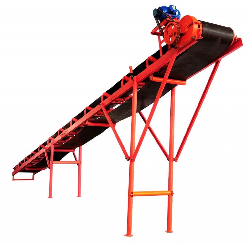
The type of belt conveyors are used to transport various materials over relatively short distances both horizontally and on an incline where the angle of the latter does not exceed 21° to 23° in exceptional cases. The material can be of almost any size and either dry or wet, but in the latter case the moisture content must be known and taken into consideration when figuring such installations. Usually the belt is supported at regular intervals by troughing rollers on the carrying side, while a number of flat rollers are needed for the return side.
Conveyor belting designed for the particular service is usually rubber covered, the upper or wearing side in many instances being further reinforced by an extra thickness of “tread” rubber which may or may not extend to the outside edge of the belt, while the under or pulley side has only a thin coat to protect the duck. Duck for conveyor belting ordinarily weighs 28 to 42 ounces and the plys from 3 to 8 depending on the factors of length of conveyor, width of belt, size of head and tail pulleys and the weight and character of material to be handled.
Supports for conveyors are usually wood or steel longitudinal members properly supported on bents and braced laterally to properly keep in alignment both the troughing rollers and the return idlers.
Conveyors are a cheap, quick and continuous method of transporting the material and when properly designed give long service. Additional data gladly furnished upon request.
Small Belt Conveyor Capacity Table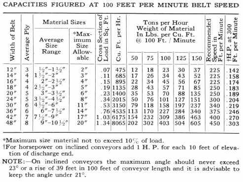
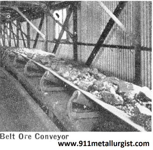
Concentrator Belt Conveyor
 A well designed concentrator conveyor system will make this ore transportation problem seem very easy.
But, like anything mechanical, there are a few guide lines that should be followed to maintain the conveyor systems efficiency.
So in the following chapter we will discuss different conveyors. Their components and some of the operating skills required to be efficient in their control.
The advantages of a conveyor are that it uses a lower energy output to revolve the flexible belt, it requires a minimum of maintenance, has a low initial cost, and it delivers the ore at a constant flow. This last is a requirement of some of the processes involved in mineral recovery.
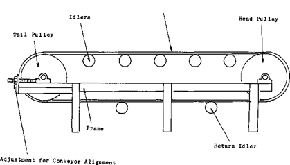
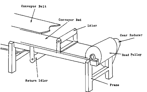
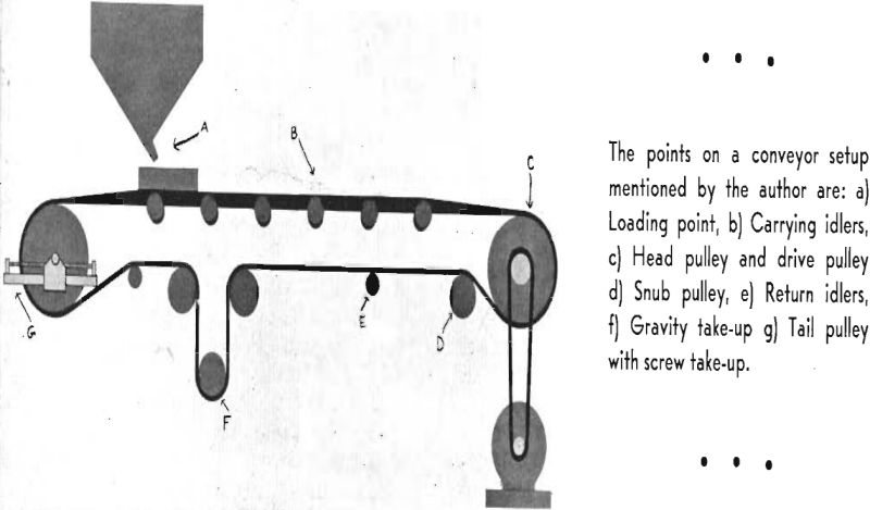
To start let’s look at three different conveyor systems, starting with the simplest. The basic components of a conveyor are the FRAME and the BED, the IDLERS.
The rollers, roll with the belt to help reduce the drag of the conveyor belt that the drive motor will have to pull against.
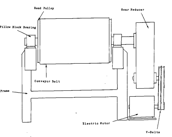
The HEAD PULLEY, This is usually, but not always, the pulley that the drive unit is attached to. The revolving pulley will pull the conveyor to it. It is placed at the discharge end of the conveyor.
The RETURN IDLERS, these support the belt for the return part of the belts cycle.
The TAIL PULLEY. On this simple conveyor the tail pulley is adjusted to maintain belt alignment and tightness.
The DRIVE UNIT, attached to the head pulley, the drive unit is comprised of, MOTOR, GEAR REDUCER, and DRIVE BELTS or CHAINS.
A gear reducer, by the way, lowers the revolutions per minute that the head pulley revolves at.
The BELT. This is a flexible surface, usually constructed in altering layers of rubber and cord. The cord may be of different material and is included in the design to prevent the belt from stretching and or breaking.
The second conveyor that I would like to describe has all the components of the first, plus a few of its own.
The most noticeable differences are the length, the size and the speed. Because this conveyor has these differences the design had to accommodate the changes.
Belt Conveyor Operation
Like everything else, each mine has its own problems when dealing with ore handling characteristics. Sometimes the ore will be very wet and sticky. This may mean using POWER BRUSHES and BEATER ROLLERS to keep the dirt knocked off of the belt face. Dust may be the problem, whatever it is, there has been equipment designed to deal with it.
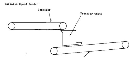
Instead of describing individual conveyors as I have been, I think we should graduate to systems that use two or more conveyors in a CIRCUIT.
In modern mills it is not unusual to find two conveyors feeding onto a single conveyor. It is also normal to find one piece of equipment feeding one or two other pieces of equipment. When this happens the conveying system that is required to deliver the ore in a steady controlled fashion can be quite complicated.
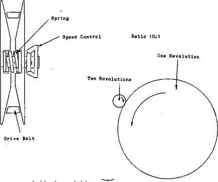
To have the equipment as versatile as possible, you must be able to adjust the rate of feed. If you remember earlier when we were discussing feeders I stated that you can control tonnage by either increasing or decreasing the volume of the ore or the speed that it is moving. When you are dealing with conveyors you pretty well have to control the speed. This will be done by changing the speed of the electric motor driving the belt or by changing the gear ratio in a GEAR REDUCER. The simplest form of gear reducer is a small gear driving a large gear. For every revolution the larger gear makes the little one has to travel farther to keep up. If the ratio is 10:1
This means the little gear will have to turn ten revolutions to make the large one turn one revolution. In some reducers this ratio may be changed.
Whenever possible the speed of any VARIABLE SPEED EQUIPMENT should be lowered to zero before it is started. This will help eliminate the stress and strain of start-up.
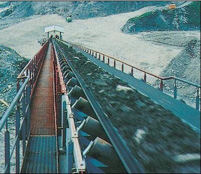
Belt Conveyors
The belt conveyors used to transport the ore in the crushing plant commonly run at 100 to 200 ft. per min. and vary in width from 16 to 36 in. according to the tonnage to be handled. Their capacities and power requirements are given in Table 4.
The belt should not be run at a greater inclination than 22°, as the ore tends to roll backwards on a steeper slope.
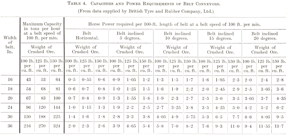
The above figures are based on normal design for heavy-duty conveyors. They are calculated for a belt speed of 100 ft. per min.; for faster travel the capacity and power figures must be increased in direct proportion to the belt speed. Usual practice is to run the belt at about 200 ft. per min., in which case the figures in the table should be doubled. The power requirements are given for a 100-ft. length of belt; for longer or shorter lengths the figures must be increased or decreased respectively in direct proportion to the belt length in feet measured from the centre of the head to the centre of the tail pulley. The capacity figures remain constant whatever the length of the conveyor depends on the distance between the bottom edges of the two jaws at the end of the backward stroke when they are open to their widest extent; this distance is determined to about half an inch by the size of toggle plates used, any finer adjustment being made by placing shims (242) behind the toggle block (240). In some makes of crusher, however, the last adjustment is made by means of a taper wedge which is situated behind the toggle block and can be moved up or down by turning the nut on the bolt that supports it. The faces of both jaws are protected from wear by manganese steel liners.
Conveyor Belt Maintenance
It is common practice, and certainly good business as all of us know, to take care of plant operating equipment. Machinery of any type requires periodic inspection and planned maintenance. With this thought in mind a plant operator should at the end of every shutdown period make regular belt inspections and plan for later appropriate care and maintenance.
The points mentioned below are understood well by all of us but are sometimes forgotten because belt conveyors are comparatively easy to operate. Maintenance of any conveyor belt is dependent upon the fundamental characteristics of the two component parts—cover and carcass.
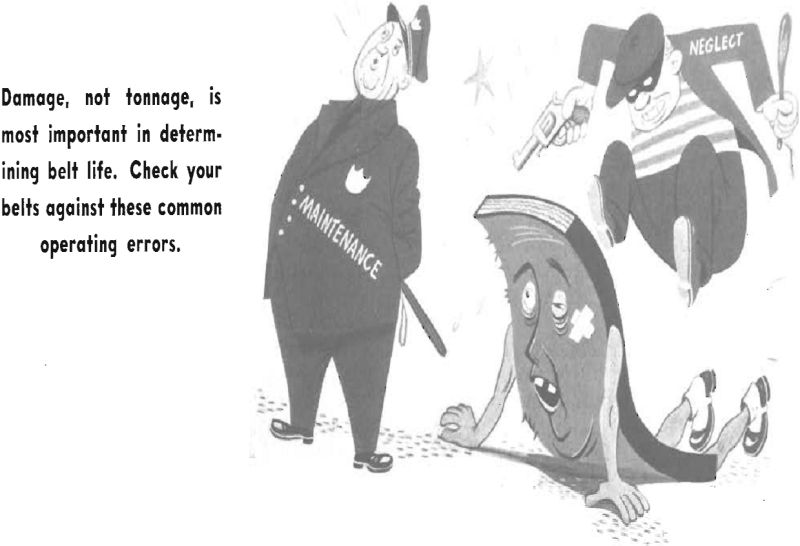
The interior cotton fabric, cord, steel cable, or synthetic fibre plies supply the main structural strength of the belt. They do the work of supporting and pulling the load, whereas the rubber covers provide resistance to corrosion, abrasion and impact. The load-carrying carcass plies are subject to many hazards such as abrasion, impact and corrosion. The rubber with which they are covered and impregnated is many times more resistant to these damaging conditions. Rubber can stand up well against abrasive action and shock impact as long as the force involved does not distort the rubber beyond its elastic limit. When the rubber cushion cover of a belt is distorted beyond its capacity to yield, the surface is cut or broken and the protective cushion torn away, leaving the interior carcass exposed to damage. Injury and damage are of far greater importance in determining how long a belt will last than the number of tons of material carried.
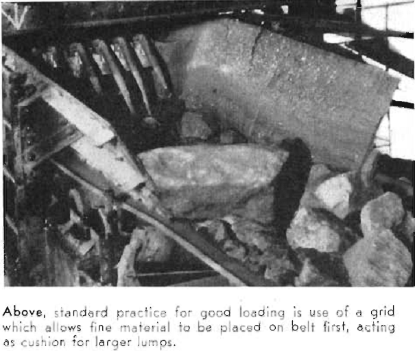
Is the load on a particular conveyor belt dropping from a height greater than necessary onto the belt? (a) Install an inexpensive short feeder belt to take the greatest abuse, (b) Use a pad belt at the loading point for severe impact loading conditions. (c) Several types of shock impact rubber-covered carrying idlers may be used at the loading point, (d) A screen or grid that permits fine material to be placed on the belt first and act as a cushion for larger lumps is standard practice for good loading, (e) For some types of loading the middle horizontal carrying idlers have been removed to eliminate hammer and anvil action.
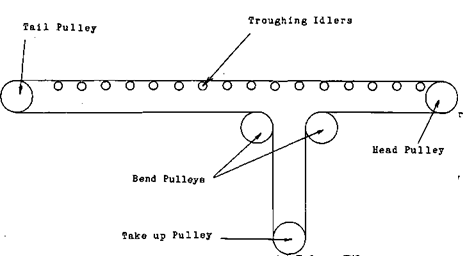
It is expected that troughing idlers, return idlers, as well as drive terminal, snub or takeup pulleys, be maintained with a clean surface for belt alignment and long life, (a) Terminal Pulleys. Granted that head and tail pulleys are of proper diameter for belt width and thickness the life of a conveyor belt is often endangered by slippage on pulleys and caused by lack of cleaning. Accumulation of such material may cause the belt to run to one side, seriously damaging the belt edge. Material may cling to the belt beyond the drive snub pulley location and then build up on return or takeup pulleys to again cause serious belt misalignment and damage, (b) High tension snub pulleys operating against the dirty side of the belt may be lagged with a ½-in. thick soft rubber lagging with smooth surface. The movement of soft rubber surface tends to brush off material buildup on the belt, (c) A layer of 3/8-in. soft rubber may be vulcanized or lagged to drive pulleys. Lateral or herring-bone grooving of the rubber pulley surface provides not only a surface movement for cleaning, but also a higher coefficient of friction for wet drive conditions, (d) The use of all-rubber wiper blades is usually most effective in conjunction with water spray.
Considerable attention should be given to return idler cleaning inasmuch as these idlers all contact the belt carrying side. As stated before, buildup on return idlers may cause the belt to run off and damage belt edge. Several means have been used to clean return idlers, (a) Carrying idlers. (1) In some conveyor installations there is a tendency for moisture to condense on idlers and combined with ore forms a coating on the moving parts of the idlers. Corrosion of metal parts may result, with an eventual frozen idler to cause misalignment.
Conveyor belts are best repaired by electrically-heated vulcanizers of the appropriate size to accommodate certain width belts. Vulcanized repairs can be made by any good plant maintenance man after a few hours of instruction. Repairs usually require replacement of broken carcass plies and/or missing cover patches with new unvulcanized stock. Belt splices are made in much the same manner as repairs using a conventional step-splice design