

Hover
")
Hover
")
Hover
")
Hover
")
Hover
")
Hover
")
Hover
")
Hover
")
Hover
")
Hover
")
Hover
")
Hover

Hover

Hover
")
Hover
")
Hover
")
Hover
")
Hover
")
Hover
")
Hover
")
Hover
")
Hover
")
Hover
")
Hover
")
Hover
")
Hover

")
")
")
")
")
")
")
")
")
")
")


")
")
")
")
")
")
")
")
")
")
")
")
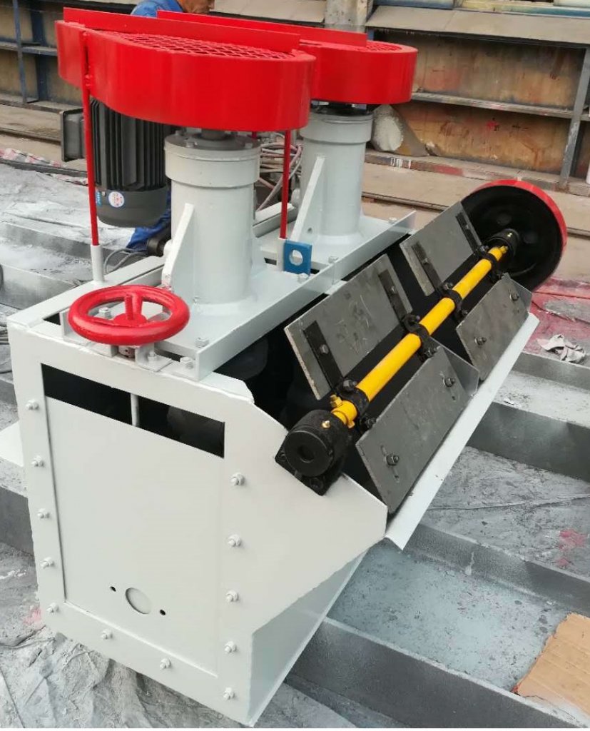
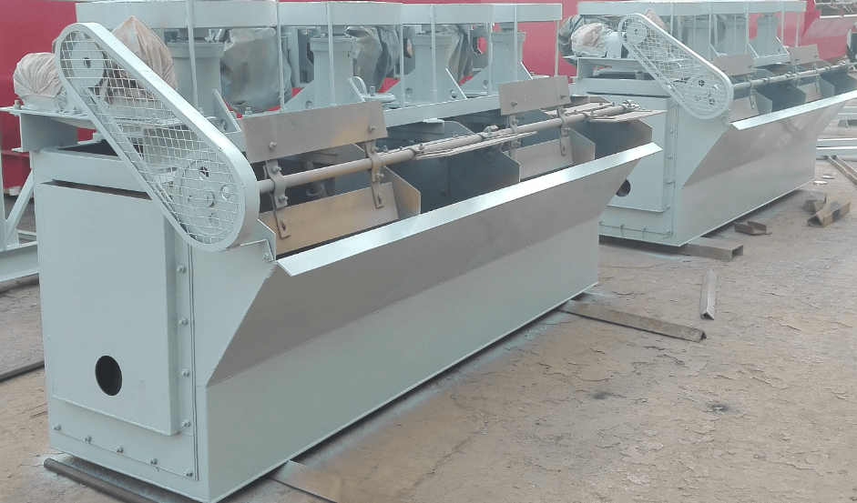
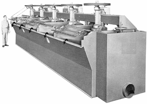
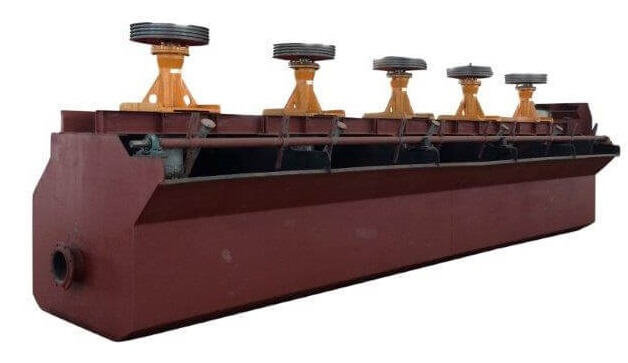
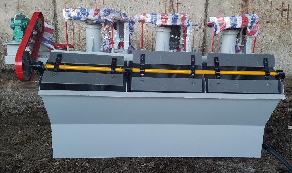
Plant Flotation Machines in Banks
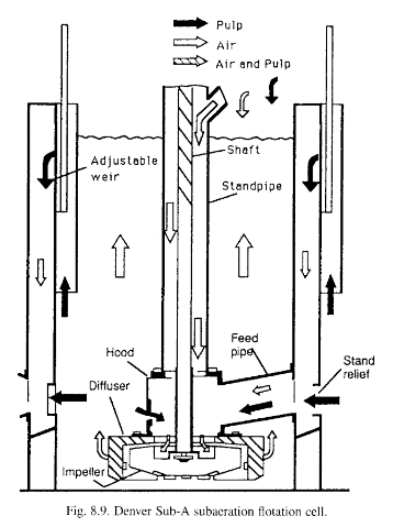
In the mechanical flotation cells the feed can be introduced directly to the impeller zone from the side as in a Denver-style Sub A sub-aeration machine.

A centrally located paddle-wheel type impeller generates a rotating pulp vortex which extends between two stationary elements: the sand-pipe located at the top of the cell, and the draft tube located at the bottom of the cell. The hydraulic action of this rotating vortex is to develop an internal cavity vacuum while simultaneously circulating the pulp from the bottom of the cell through the. draft tube into the rotor region. The suction developed in the vortex core draws air into the central region of the rotor which is mixed with the pulp circulated from the bottom to the cell.
Mineral flotation starts with grinding of the ore, with water and reagent, down to a chosen average grain size to secure “liberation of the discrete mineral particles. This step raises a difficult mineralogical question; as perfect liberation is rarely achievable without excessive over-grinding, what defines the economic compromise?
Contact 911Metallurgist with your specific needs.

Description
The “pulp” (i.e. mineral-water slurry after grinding) is commonly passed through a hydrocylone to concentrate the “sands” and reject the “slimes” (the finest size fractions, say 30um), the slimes are objectionable in several respects: they are slow to float, the consume a disproportionate share of the reagents, and they may seriously spoil the selectivity of flotation of the sands by “slime-coating” them. There are sound arguments, in any case, for processing coarse and fine fractions separately.
The pulp is “conditioned” for a few minutes with reagents designed to accentuate differences of floatability of the various mineral species. An appreciable time is required to achieve good distribution of the reagents and to allow give-and-take competition between different mineral particles.
The conditioned pulp is run into a flotation cell, which is crudely a box with a stirrer, and a means of introducing air. Typically, the cell might contain 15-30% by volume of entrained air with bubbles ranging mainly from 0.1 to 5mm in diameter; the “pulp density” might be 25-40% of solids having a particle size ranging from 10-100um. The flotation grains are caught by bubbles and carried to the top of the cell, forming a froth, which is automatically scraped off over the “lip” of the cell, where it collapses and flows away in a launder. The frothing action is quite important. A moderate depth of froth is necessary to allow some back-drainage to take place, with release of non-floated particles which have been, unavoidably, entrained to some extent between the bubbles. Here is another reason why “slimes” are a nuisance – they remain too long in the water between the bubbles and so reduce the “grade” of the floated product.
The first stage of flotation of the pulp amounts to a quite short average “residence time” in the “rougher” cell before it passes out, largely depleted, from the bottom of the cell. In a conventional flotation plant no attempt is made to engineer a perfect separation in one stage. Instead, both fractions leaving the rougher are re-treated at least once in “cleaner” and “scavenger” cells, respectively. Scavenger cells, in effect, prolong the flotation time, while competition for bubble surface is reduced. The net of the recycling and re-treatraent is improvements in the separation (“grade”) and proportion of valuable minerals obtained (“recovery”). As the latter is usually a minor component of the ore, it is preferable to float it, in preference to floating the much greater proportion of gangue; but in some cases the gangue is floated (“reverse flotation”).
It is a characteristic feature of flotation plants that the cells are comparatively small, but rows and rows of them are run in parallel to increase through-put and in series to improve grade. If more than one mineral is to be extracted, the pulp is re-conditioned with other reagents and further stages of flotation are operated. The engineering is simple, continuous, amenable to adjustment, and needs little operator attention. The “concentrates” from flotation are generally filtered, washed, dried and bagged for transport as powders.
 |  |
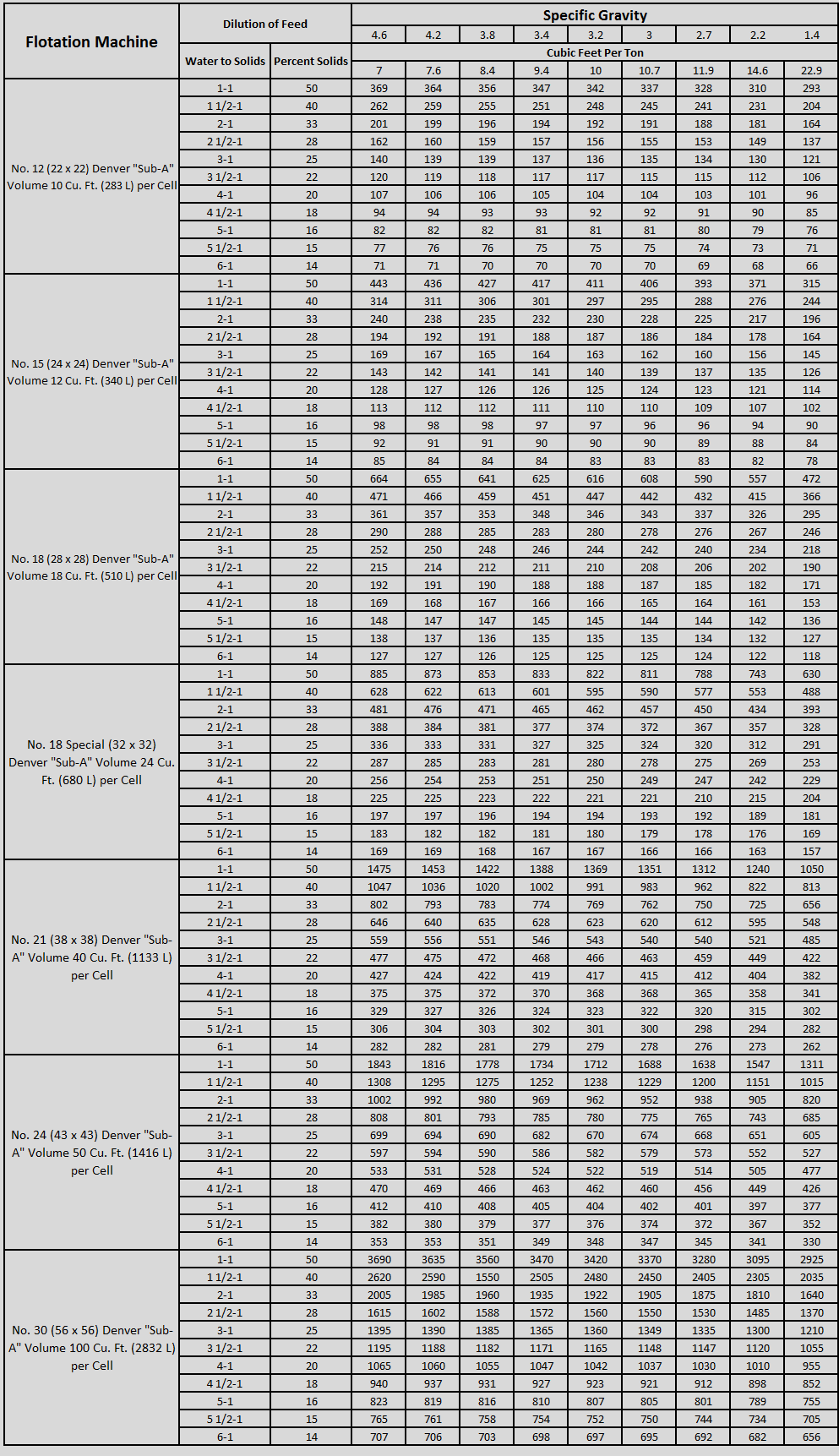
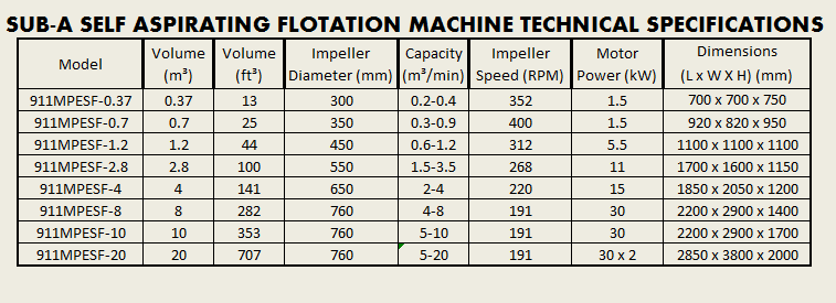
PROBLEM 1 – How many No 15 (24×24) Denver “Sub-A” Cells are required to treat 50 tons of gold or load ore per day, with treatment time 12 minutes, dilution 3 to 1; and SG. 3.0 ?
Tons (14 hours) x Treatment time (minutes)/Tabulated tonnage figure = 50 x 12/162 = 3.7 cells
- ANSWER – The result is 3.7 cells, thus use 4 No. 15 Denver “Sub A” Cells.
PROBLEM 2 – How many No. 18 Sp. (32×32) Denver “Sub-A” Cells are required to treat 125 tons of load-zinc ore per day, with treatment time 14 minutes for the lead, dilution 3 to 1% and with treatment time 16 minutes for the zinc dilution 3½ to 1. and sp. gr. 3.4 ?
- ANSWER – (lead) 125 x 14 / 327 = 5.4. thus use 8 No. 18 Sp. Cells.
- ANSWER – (zinc) 125 x 16-/281 = 7.2. thus use 8 No. 18 Sp. Cells.
 |  |
| 
|
 |
Aspects of Flotation Scale-up Requirements
Scale-up denotes the procedures for designing larger units of equipment for which smaller units are available with known operating characteristics. Such procedures are well established for chemical engineering equipment, particularly mixers, of which flotation cells are examples, although complex ones.
The bases for extrapolating design are the principles of similitude, including both geometrical and dynamical aspects. If full geometrical similarity is maintained in an equipment family, then once a single new size aspect is selected, for example, volume or impeller diameter, then all other dimensions are automatically established through the scale factor.
The dynamic aspect refers to the fluid motions involved and for mixers and flotation cells more specifically to the impeller speeds and energy inputs. It is here that complications arise. For relatively simple mixing problems, as in conditioners, where it has been established that power intensity is a scale-up factor, it can be shown that for contant Power Number and constant power intensity the relationship
N3D2 = constant
obtains. Once D is fixed arbitrarily according to the new system size, then the rpm N is also automatically fixed.
However, in a flotation cell, the presence of air and the further necessity for balancing air and pulp flows to satisfy both flotation and suspension requirements simultaneously, introduces at least one other variable: air flow Qa; and at least one other dimensionless group the Air Flow Number Qa/ND³. This may also be expressed as Qa/A/ ND
Furthermore, it cannot be assumed that either the Power Number or power intensity will be constant on scale-up; in fact, it is evident in Table 4 that power intensity decreases.
A further complication is that most families of cells have grown in size without rigorous scale-up procedures, (see Harris) Wemco does appear to have scaled its impellers closely to (cell area)½, i.e., D/L = constant, but this is not the case for Denver or Galigher. Cell depths now increase regularly for both Denver and Wemco, but not for Galigher.
Thus, at best, no automatic procedure for scale-up appears possible. Those published by Denver and Wemco illustrate the necessary mixture of rational and experimental steps. Wemco decided upon a 28 m (1,000 cu ft) cell and apparently also upon a .76 m (30 in) impeller diameter, which continues the D/(Area)½ ratio of 0. 227. Extrapolation of empirical relationships among air and liquid circulations, submergences, and HP, N, and D established ranges, but actual testing with a prototype was necessary to arrive at an impeller speed and submergence combination and to establish clearances. Finally capability of the selected combination for sand suspension was established experimentally.
For its largest cell, Denver first decided to use a 56 KW (75 HP) motor, as the largest compatible with a V-belt drive; with safety factors for start-up and overload this gave a 48 KW (65 HP) design criterion. Relationships were established from measured smaller cell operating characteristics among pumping rates, power draws, depths and cell volumes. These, with HP fixed and depth selected, resulted in fixing the volume at 36 m³ (1275 cu ft). The effects of clearances and independent variation of air flow on power draw were tested in a prototype as were the sand suspension capabilities.
Of interest was Denver’s use of averaged fluid rise velocities as design criteria for proper sand suspension. These decrease from about 4 m/min (13 ft/min) in their smaller cells to 2.8 m/min (9 ft/min) in the 36m³ cell. Figures are similar for the Wemco cells but increase rather than decrease. These velocities are a rough measure of the maximum particle mass which can be suspended, although suspension in the sense of uniformity is a misnomer. As both of the studies show, there is segregation of coarser sizes. Only the finer sizes move uniformly throughout the cell with water flow, while coarser sizes find more restricted flow paths in appropriately higher velocity streams in which they circulate. In the limit, if a high enough velocity region does not exist, sizes requiring such a velocity settle out.
The three principal U. S. cells have had decades of intense competition world-wide. In addition their innovations in increasing cell volumes by factors of twenty in recent years have paid dividends in much lower power intensities. If at the same time unit capacities remain reasonably close to those of smaller cells, then any new designs may have difficulties in breaking into the field. Exceptions may well be in coarse particle handling for which conventional cells definitely have limitations because of their need to be versatile over the broadest possible range, with some sacrifices necessary.
The main hope for significant improvements rests on further quantification of relationships among flow, aeration, and process kinetics as related to particle size particularly. It may be that adjustment of the cell control parameters either in separate circuits for different size ranges, or in different parts of the same circuit, with the air and impeller speed adjustments as part of the control network along with reagents, will be the trend of developments for the future.
Appreciation is expressed to representatives of Joy Manufacturing, Envirotech (Wemco) and Galigher (Agitair) for providing information in advance of publication.
Hydrodynamic Aspects
The following conclusions are based mainly on the Denver and Wemco publications:
- For Wemco cells, peripheral speeds increase fairly regularly as D 0.2. Although the increase is less regular for Denver cells, they do show about the same dependence of ND on D over the full range of cell sizes.
- Power intensities decrease exponentially with D. This means that flow intensities, as volumes/volume of cell contents, also decrease markedly with cell sizes.
- Both air escape velocities and pulp flows expressed as rise velocities are more or less constant with increasing cell sizes. These are both critical process requirements. They are satisfied by decreasing volume flows (as in 2 above) because of decreasing ratios of areas to volumes through increasing depths. If cell specific flotation capacities as tonnages/volume are constant with increasing size, a fact not yet demonstrated for the largest sizes, this will argue for increased flotation cell efficiency with sizes both with respect to air utilization, and to energy requirements.
This would follow from the decreased ratio of area to volume with increasing depth, and thereby the lowered volume flow requirements to obtain the same linear velocities for air and pulp. In the case of air, this suggests that increased depth of cell favors more efficient utilization of air because of the longer path per bubble and the greater probability thereby of maximum loading per bubble. However, for the same reason, there may be a depth limit beyond which no further increase would be obtained.
Economic Aspects
The economic advantages of larger cells have been shown in several publications.
In brief outline, these include: lower investment costs, lower installation costs, lower labor costs, and lower costs for controls. If lower power intensities at constant capacity per unit volume are borne out, then power costs per tonne would also be lower. In addition the reduction in the number of units necessary and the higher capacities per unit of floor space should result in lower indirect costs for buildings. There is a probable present limit to further increases in size if only because there are no plants in sight above the 100,000 tonne/day capacity level. At this tonnage, four rows of 12 cells, or fewer rows of greater length, of the largest presently available cell sizes would be adequate.
The indicated savings in flotation equipment costs only vary for 2.8, 8.5, 14.2 and 36.1m³ (100, 300, 500, 1275 cu ft) cells as 1.00 /0.60 / 0.45 / 0.37 and for 1.7, 14.2 and 28.3 m³ (60, 500, 1000 cu ft) cells as 1.00 / 0.52 / 0.39. Even if further savings in power intensities with still larger cells do not materialize, costs per unit of capacity for equipment, installation, and building should continue to decrease, but at a lower rate with continued increases in size.
Although there has been the implication that the very large cells should be considered only for the largest plant capacities, this is not necessarily correct. Attention is being given even for smaller plants to splitting circuits between roughing and scavenging; using one or a few of the larger cells at the head of a bank, or even for the entire tonnage as roughers to take out the fastest floating 50 to 75 percent of the mineral; and the completing the scavenging with the appropriate number of smaller cells to provide the time and the appropriate conditions of aeration and agitation for the slower floating coarse, middling, or altered surface minerals. In this way controls could be centralised in roughing, particularly if the scavenger concentrate could be recycled to the rougher, and different cell conditions could be adapted to the different requirements.
Newer Cell-Design Concepts
Impellers are the main differences among older mechanical cells; of novel types few are entirely new; and several are revivals of concepts going back to the first decades of practice. They can be divided into the following groups: a) injection types with pressurized introduction of feed through nozzles, which simultaneously aspirate air and mix it with the feed; b) froth feed types, which add new feed into or close to the froth; and c) cells with different fluid moving mechanisms.
Injection Cells
Three cells of this type have been in commercial development over the past two decades: (1) the Heyl and Patterson CycloCell; (2) the Deister Flotaire, originally developed by Hollingsworth for Borden Phosphate in Florida; and (3) the Davcra Cell, developed by Davis for Conzinc Rio Tinto in Australia. Although all three use nozzles for air ingestion and mixing, the CycloCell uses a pump with recycle of cell contents through the pump/nozzle; the Flotaire substitutes water-main pressure for pumping by injecting fresh water through the nozzle for air aspiration; and finally, the Davcra uses a pump/nozzle to inject feed through the side of its cell without recycle back through the pump.
The practicality of the CycloCell has been established through extensive applications to coal flotation, and it has been tested on Florida phosphate. The Davcra has been used for special applications at Palabora and Bougainville and at locations in Australia, but it is understood that its further development has been discontinued. The Flotaire Cell has only recently been taken over by Deister who are attempting to develop applications in fields other than phosphate. The injection principle appears interesting both to supply and mix air and to provide the fluid energy for particle suspension. The important question is whether external pressure supply with loss of head through external piping and a nozzle is more or less efficient than a submerged impeller whose kinetic energy is dissipated entirely within the cell and presumably for useful purposes.
Froth Feed Cells
Three examples of this principle are known: the Flotaire Cell, already mentioned; a cell designed in the USSR employing the principle, but calling it “froth separation” , and a cell designed by Paul Smith of Colorado SMR Institute All use the same arguments and general approach: a) that a major flotation
problem is the recovery of the coarsest sizes; b) that much of the energy required by flotation is for suspending coarse particles; and c) that, therefore, by adding feed directly to the froth the coarse particle problem is largely eliminated.
The proponents of all three cells can show impressive results mainly with coarse phosphate feeds, although the Russian cell is apparently in operation on other applications also. But two questions must be raised. Since the principle obviously has its greatest potential for coarse feeds, how does it compare with other specialized processes such as belt flotation, spirals, and the Lang launder, all developed and in use for similar applications. A second question concerns the behavior of fines. For these sizes what is an advantage for coarse particles becomes a disadvantage: below some size limit particles will have insufficient residence time in the froth to drain out by gravity and will be carried out in the froth product. This effect could be more severe with this type of cell than with convential cells, suggesting that sized feeds may be necessary to cope with it.
New Fluid Moving Devices
Apart from the external pump, and specialized impeller designs which claim better mixing or more effective aeration, the Outokumpu Cell being an example of the latter, a novel device is the Mekhanobr Vibromachine (USSR). This utilizes a flat paddle oscillating along a vertical axis at about 600 cycles/min with a few mm amplitude; air is admitted through perforations in the paddle during the up-stroke. The effect should resemble a high-frequency jigging action which should produce a fluidized bed-type suspension, possibly with less long-range circulation of pulp than in impeller type cells. Again the principle appears interesting and possibly requires less energy for flow induction, but in the absence of comparative data, no judgments are possible.
Liquid Flow and Total Flow
Air flow is actually a direct consequence of liquid flow for a self-aerating cell such as the Wemco. For all other mechanical cells air and liquid flows are independently variable, air through adjustment of supply, and liquid by impeller speed variation. Table contains a number of derived properties of Denver and Wemco cells covering the full ranges of cell volumes. Although availability of such data is too recent for any firm conclusions to be drawn, there are a number of trends evident.
- As already noted, the property remaining substantially constant over the full range of sizes for both cells is the specific air rate, averaging near.1.3 m/min(4 ft/min).
- The Air Flow Numbers differ only slightly and decline moderately with increasing cell
size. - The total flows expressed as velocities, are less regular than air flows, and appear to behave oppositely: Wemco increasing and Denver decreasing with increasing cell volume. On the other hand the Total Flow Number is constant for the Wemco but decreases for the Denver.
The important aspect of these cell characteristics is not so much the actual values cited but that they are criteria of optimum cell operation. Too often, cell aeration and impeller speed are accepted as unchangeable instead of as potential control variables capable of manipulation, and in this respect have at least equal importance to reagent control. Thus, air flow is already being used to control concentrate grade at Mt. Isa. With the trend to larger and fewer cells, and coarser grinds, it may be advisable to control impeller speeds also, particularly for very coarse feeds, and to find the balance between these two controls for each operation.
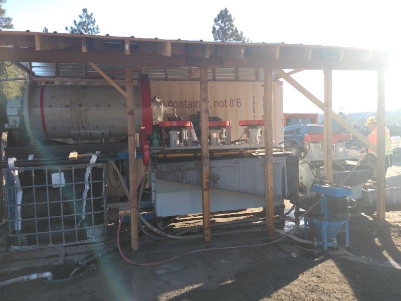
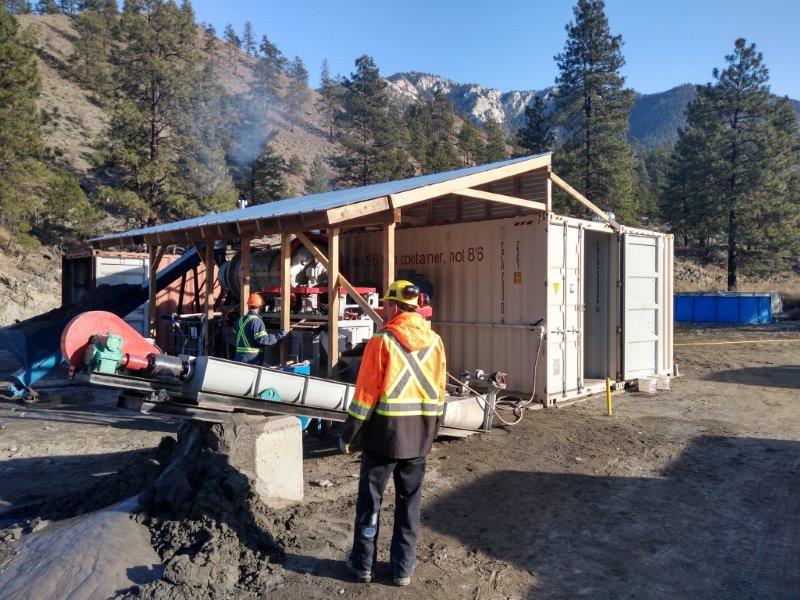
Flotation Machines
As pointed out previously, the float machines were selected as 170 cubic foot Agitair machines for circuit flexibility. In our case we might have used 300 cubic foot machines or perhaps 500 cubic foot as the trend today is to go to larger and larger units which was considered, but eliminated for the flexibility factor. If we had selected 500 cubic foot units and utilized 5 units as roughers instead of 14 and 3 units in the scavenger area instead of 8 units, the cost savings in unit cost per cubic foot would be substantial with a resultant savings in building area. Due to the costs of building concentrators in these inflationary days, the larger units must be considered. 1,000 cubic foot units are now available and will soon be in operation.
Dilution water for the flotation circuit is derived from two sources. Concentrate thickener overflow water gravitates directly to the recleaner feed sump for dilution in recleaner flotation. Process water additions are made to each of the rougher, rougher scavenger, cleaner, recleaner and cleaner scavenger concentrate launders and to the regrind cyclone feed sump.
In addition, fresh water sprays are located above each concentrate launder for froth suppression.
Vertical pumps are used for froth products and horizontal pumps for tailings and cyclone feeds. All seven banks of flotation machines are fitted with bubble-tube automatic pulp level controls and are Galigher 170 machines.
The circuit design permits the following by-pass strategies to be adopted:
– routing of cleaner scavenger tail direct to final tail.
– routing of cleaner concentrate to final concentrate .
– redirection of regrind cyclone overflow from cleaner feed to recleaner feed.
– by-pass of the regrind cyclones and hence the regrind section.
– routing of rougher concentrate to recleaner feed.
– by-pass of concentrate thickener overflow to the regrind cyclone feed sump and tailing thickener overflow sump.
Space has been provided in the flotation section layout for a talc flotation circuit, but no detailed design has been carried out. Its implementation will be dependent on the nature of the ores to be treated and is as follows:
The process flow diagram has been developed for the flotation of these talcy ores. The process depends on the rapid flotation of talc in this rougher flotation stage followed by three stages of cleaning of the rougher talc concentrate.
The talc rougher tail and three-stage cleaner tails are all directed to the No. 1 rougher scavenger bank which in this configuration becomes No. 1 copper rougher bank. The cleaned talc concentrate is discarded to final tail.
Flotation feed passes through one stage of rougher flotation, with rougher flotation tailing passing successively through three stages of rougher scavenger flotation. The unfloated product from the third rougher scavenger section is flotation tail. Rougher concentrate is refloated successively in cleaner and recleaner stages, with the recleaner concentrate leaving the flotation circuit as final concentrate. Cleaner tailing gravitates to cleaner scavenger flotation and recleaner tailing gravitates to cleaner flotation.