
")
Hover
")
Hover
Hover
")
Hover
")
Hover
")
Hover
")
Hover
")
Hover
")
Hover
")
Hover
")
Hover
")
Hover
")
Hover
")
Hover
")
Hover
")
")
")
")
Benchtop Laboratory Muffle Furnace
US$7,770
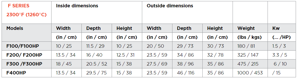
Whether you need your floor mounted (stand alone) or Benchtop Laboratory Muffle Furnace for Heat Treatment & Pyrolysis, the table top “F” series are small furnaces for heat treating, laboratory and jewellery applications at maximum temperature of 2,300°F. These furnaces offer a rugged industrial construction with a top quality coating.

Characteristics
- Sturdy Construction
- Small Compact Design to Fit in Labs and Smaller Shops
- Reliable
- Easy to maintain and service
- Incomparable service
Applications
- General Heat Treatment
- Research & Laboratory Work
- Pyrolysis Process
- Investment Casting
- Jewellery
High Performance
Our benchtop muffle furnaces integrate quality components and superior workmanship, for maximum performance in a variety of industrial or laboratory applications, at temperatures as high as 2300°F (1260°C).
Our Heavy duty construction creates a rugged furnace design which incorporates quality hardware to a heavy gauge casing, for increased durability in all type of processes. These tabletop units are available in either a green enamel finish or oxidation resistant stainless steel.

Description
Long Service Life & Ease of Maintenance
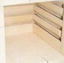
The specially designed grooved bricks optimize heat transfer and fully support the FeCrAl heating elements for maximum life expectancy. The “open coil heating elements” are easily accessible for maintenance.
Quality Insulation
The highest quality low-density refractory bricks used in the construction of its chamber assure maximum insulation while minimizing heating or cooling cycles.
Superior Heat Distribution
A special attention is given to the distribution of the heating elements to assure optimal temperature uniformity throughout the furnace.
Greater Versatility
A wide choice of options gives our units the flexibility to suit a variety of commercial, industrial and laboratory heat treating applications.
Muffle Furnace Characteristics
- Cabinet design & construction choice of Enamel coated 16 gauge steel or (304) stainless steel
- Horizontal opening door heavily hinged door With a 180° opening
- Insulation 4½”/11cm pre-grooved refractory bricks (With the exception of the f50, which is 2 ½”)
- Temperature controller microprocessor temperature controller, with auto tuning pid parameter offering ramp/soak program capability
- Heating elements low watt density fecral heating elements
- Furnace chamber hearth plate the furnace comes standard with a cordiorite hearth plate.
Furnace Options
- Vertical opening door Counterbalanced guillotine lifting door with “Zero weight positioning”
- Furnace floor stand Heavy-duty furnace stand
- Ni-cr heating elements Special heating elements used in corrosive environment
- Programmable controller 2 programs with 8 segments ramp/soak
- Solid state relay (ssr) For increase temperature accuracy and silent operation
- Adjustable exhaust vent Slide gate located on top of furnace to vent corrosive vapors, also comes with a peephole in door
- High limit controller Automatically shutdown heating elements when maximum temperature is exceeded
- Door safety switch Automatic Shut off heating elements when door is opened
- 3 phase 208-240v Available for the F300/F400
- Heating elements in door Offers greater heat distribution
Standard Laboratory Muffle Furnace Model
- PRODUCT FEATURES: all models are made of 14 ga steel (green enamel finish).
- QUALITY INSULATION: low-density refractory bricks, 4½” thick 2,300°F rated.
- LONG SERVICE LIFE & EASE OF MAINTENANCE grooved bricks optimize heat transfer and make maintenance much easier. FeCrAl heating elements are located into the groove of the bricks (but not moulded into the brick) and can be replaced without taking any bricks out. By being in the brick groove, radiant heat from the element is lowered, which offers a better temperature uniformity. The elements are protected from any contact that can occur during the furnace loading. This kind of design also allows the operator to replace just a few bricks when required.
- ACCURATE TEMPERATURE CONTROL: standard controller used is Watlow model PM6 (1/16 DIN) (Single set point controller). Base unit for simple applications. Just input you’re work temperature and let the Watlow EZ-Zone PM6 do its job with its precise PID control feedback loop. This unit also includes built in high limit (HL) overheat protection. HL is easy to program and reset.
- HORIZONTAL OPENING DOOR: heavily hinged door with a 180° opening. We offer a rugged industrial door design.
- FURNACE CHAMBER HEARTH PLATE: all furnaces come with a Cordierite hearth plate.
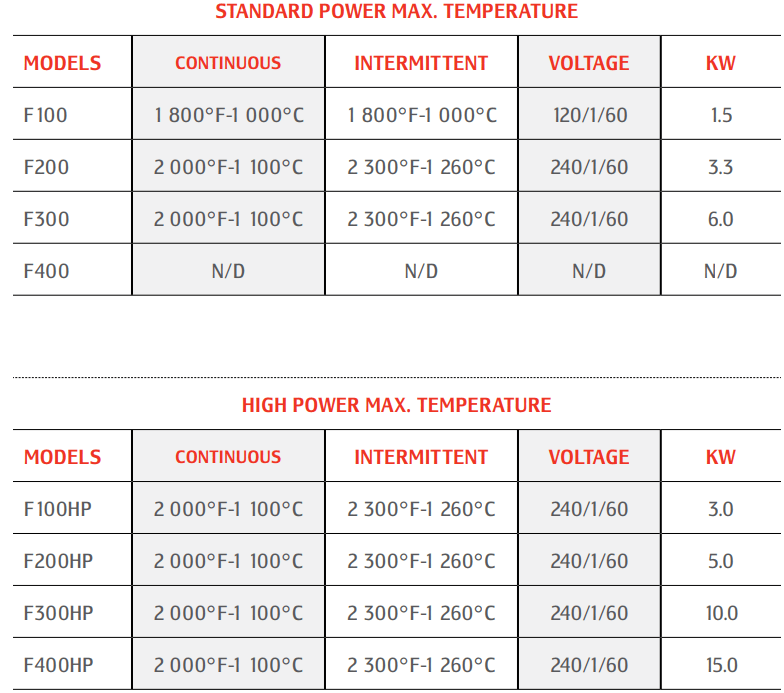
Model Power Output
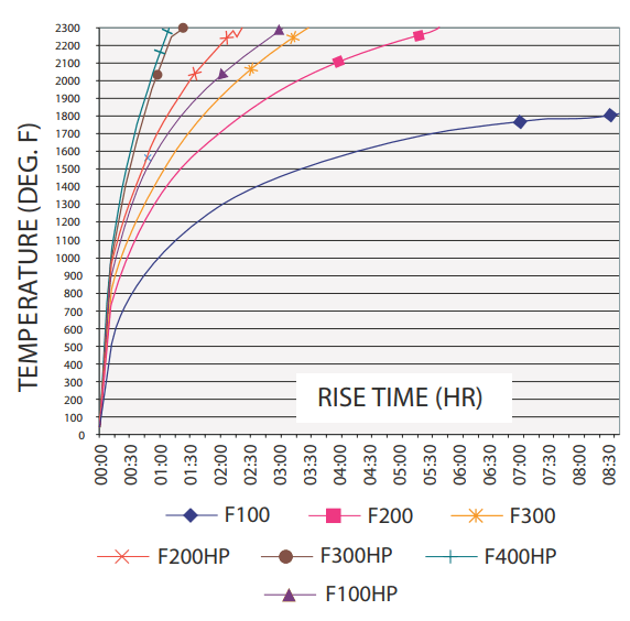
- “HP” MODELS: ramp up time is faster than standard models (see brochure for time Vs. Temperature curves). The “HP” version is especially appropriate when ordering the slide gate chimney option described below.
Options
Controls & Instruments
- PROGRAMMABLE TEMPERATURE CONTROLLER (4P/10S): Basically the same unit as the single set point unit but with programmable Capabilities. You have four (4) programs with 10 segments per program for a total of 40 segments. You can program your ramp-ups, soak and ramp down time temperature. This system permits you to have defined programs linked to your processes and treatment necessities. This unit also includes built in high limit (HL) overheat protection. HL is easy to program and reset.
- USB COMMUNICATION: This add-on USB port links up to your programmable temperature controller. By using you’re the freeware provided by Watlow and a laptop permits you to quickly modify or set recipes and change desired parameters.
- PROCESS TIMER: This unit paired with standard single set point temperature controller makes the easiest way to use our furnace when dealing with simple process requirements. Just set quantity and desired units, countdown will start when set temperature is obtained giving you consistent soak times. After soak time is finished unit shuts down and awaits next command from operator.
- 7-DAY TIMER: This option permits you to have the furnaces start automatically at defined time. Perfect to pre-heat furnace.
- SSR: This electronic part increases control accuracy in soaking and is much quieter than the mechanical contactors. Makes for a more sturdy electrical system because you don’t cycle contactor.
- TEMPERATURE CONTROLER/RECORDER: Info to come
- PAPER CHART RECORDER: Info to come
Furnace Door
- VERTICAL OPENING DOOR: counter weighted vertical opening door offered on all models. Makes loading parts in furnace easier and safer. Both hands can be used to handle parts.
- HEATING ELEMENTS IN DOOR: Elements in the door are available for F300 and F400 models only. Customers will need this option usually for burn-off applications or to prevent condensation on the door. Can also help in lower temperature uniformity (around 1100°F).
- DOOR SAFETY SWITCH: automatically shuts off the power to the elements as door is opened and restores it as door is closed. Prevent accidental electrical socks if operator touches live element with metal tongs. This option is also provided with horizontal hinged door with elements in door to prevent accidental scorching.
Other Options
- ADJUSTABLE EXHAUST VENT: it’s a slide gate on top of the furnace in case corrosive vapours have to be vented. When this option is selected, a peephole is included.
- NiCr HEATING ELEMENTS: at no extra charge. These elements are usually used for corrosive applications, in Nitrogen atmospheres and for Dental Lab applications.
- CORRUGATED HEARTH PLATE: This hearth plate is corrugated permitting you to complete lost wax process thus letting melted wax to be funnelled in the bottom of the furnace.
- SS 304 CASING: This option especially suited for dental laboratories and corrosive applications.
- FURNACE FLOOR STAND: we offer a heavy-duty floor stand. Can be ordered at specific high.
- INERT ATMOSPHERE (OPTION): This option allows you to generate a protective atmosphere in your oven at high temperature. Such type of atmosphere minimizes oxidation of the steel pieces. This option includes the following items:
• N2 gas panel
• Pressure regulator – 30ZAA201595680100000
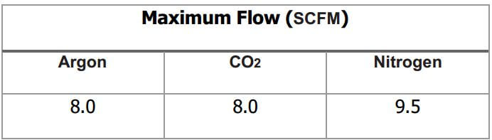
º flow meter calibrated for nitrogen (N2) with integrated flow control – MAX 9.5 scfm (N2)
Laboratory Muffle Furnaces Specifications
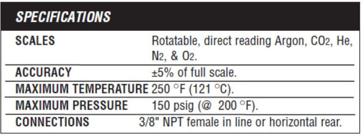
Other Gases
- Valves & Piping necessary; mounting oven
- Ports: Input / Output
Benchtop Muffle Furnace Maintenance
Lets take a minute to talk about some of the parts which need to be maintained in your furnace. First, it’s the heating elements. We use a heavy-gauge wire with a low lob loading for a longer life. The wires are supported in removable plates. When a wire does burn out, the entire assembly with the wire slides out, a new plate with the wire slides back in. You do not have to touch or remove the insulation when replacing one of our heating elements.
Next, is the hard plate. The floors in our chambers are aligned with a dense plate which we call the hard plate. It protects the softer insulating fire brick underneath and supports the workloading. If the plate cracks, it can be removed, slides out through the front, the new plates slides right back in. Next, is the insulation. The insulation in our furnaces has always consisted of insulating firebrick. Our models is dry fit; it’s wedged in place which is better for thermal contraction and expansion as the furnace heats and cools. The bricks can be replaced individually. Mortaring is neither necessary or recommended.
Also, just to dispel concerns about the white insulating material, please note that insulating fire brick does not and has never contained asbestos. Finally and perhaps most important is your thermal couple. The thermal couple is the probe which senses the chamber heat, sends a signal to the temperature controller telling the furnace to cycle on and off. We recommend replacing the thermal couple every 6 months to a year to maintain accurate control and help your heating elements operate more efficiently and last longer.
We stocks all of these parts I talked about and can be generally shipped in one to two days. Installation is easy with minimum downtime and will help keep your furnace in operation for many years.
General Furnace Operating & Maintenance Instructions (F400HP)
 |  |
Caution
 | READ THE INSTRUCTION MANUAL Read and understand operator’s manual and all other safety instructions before using this equipment. |
 | KEEP THIS DOCUMENT FOR FURTHER CONSULTATION
|
 | ELECTROCUTION DANGER Do not unscrew the back or front panel before first closing the power source adequately.Do not touch the elements. |
 | HOT SURFACE Furnace outside shell can be hot when in service. Do not touch. It is the responsibility of the customer to provide the operator with appropriate heat protection in accordance with the furnace usage. |
 | CRUSHING DANGER Do not put your hand between the furnace and the door while closing the door. |
Make sure your installation complies with the local authorities and with the appropriate NFPA Standards, which are available from the National Fire Protection Association.
These NFPA standards include, but are not limited to:
- National Electrical Code, NFPA 70
- Electrical Standard for Industrial Machinery, NFPA 79
- Standard on Incinerators and Waste and Linen Handling Systems and Equipment, NFPA 82
- Standard for Ovens and Furnaces, NFPA 86
- Standard for Chimneys, Fireplaces, Vents, and Solid Fuel-Burning Appliances, NFPA 211
Please note that a non-compliant installation can result in risks of fire.
This information is valid as of May 2014, please contact PYRADIA for more complete and up-to-date information.
Warning
Even though this new equipment is designed and manufactured with the best possible components, it is strongly recommended not to leave the equipment operating without any strict supervision; in order to avoid any potential damage resulting from a defective component or an operator’s wrong setting.
The presence of safety components on this equipment cannot, in itself, assure absolute safety of operation.
For a safe operation, there is no substitute for a diligent, capable, well-trained operator.
It is the sole responsibility of the user to establish, schedule, and enforce the frequency of and the extent of the inspection/maintenance program because only the user can know what the actual operating conditions are.
Operating Features
Electrical Power Supply:
Refer to the nameplate and the electrical diagram in Appendix 4.
Maximum Operating Temperature With:
| Continuous | Intermittent | |
| Air | 2000 (1090) | 2300 (1260) |
| Nitrogen | 1920 (1050) | 1920 (1050) |
| Nitrogen (with pre-oxidized elements) | 2000 (1090) | 2190 (1200) |
Muffle Furnace Installation
The furnace is shipped pre-wired and ready to hook up to your electrical supply.
- DO NOT INSTALL FURNACE CLOSER THAN 12″ FROM ANY SURFACE.
- For proper door operation, install the oven at level.
- Install the oven on its structure or a sturdy table. If necessary, fix the table to the floor and secure the oven on the table.
- Remove packing from furnace interior.
- Remove back panel connection cover.
- Refer to the nameplate on the oven and to the electrical diagrams of Appendix 4 to ensure proper electrical connections.
- Place hearth plate in the furnace chamber. On furnaces equipped with elements in the floor, make sure to place hearth plate on spacers so that the plate is not resting directly on the elements.
Evacuation Chimney (Option)
If your process produces toxic fumes, it will be necessary that the exhaust duct, on oven roof top, gets routed to the outside and that it is not obstructed.
NOTE : It is your responsibility to conform to local regulations.
Pneumatic Door (Option)
Supply 80 PSI (1 SCFM) of compressed air to the valve inlet.
Inert Atmosphere (Option)
Hook up the inlet and outlet inert gas piping to your system.
Initial Firing
Also refer to the “Operating Instructions” section.
To validate the warranty, the following initial firing schedule has to be respected in order to eliminate the moisture remaining in the refractory.
Because the refractory contains a certain amount of humidity, the first step is to maintain the temperature below water boiling point. This will prevent vapor accumulation that can cause cracks in the refractory.
- Bring up gradually the temperature to 200°F (93°C).
- Hold at 200°F (93°C) for 6 hours with door slightly open. By-pass door switch if necessary.
- Increase temperature by 150°F (65°C) per hour until it reaches 1000°F (540°C).
- Close the door and maintain at 1000°F (540°C) for 6 hours.
- Either shut-off and cool down or bring up to normal operating temperature if equipment is to be used at that time.
NOTE 1: If the oven is equipped with the programmable controller, profile (program) 1 has been configured to follow this heating schedule. Run profile 1 to start this initial firing and keep a vigilant eye on the furnace. Information on how to use the controller is included in Appendix 3.
NOTE 2: Some cracks may appear in the refractory and cement after the initial firing has been completed. It is common and will not prevent the oven from working properly.
NOTE 3: This procedure does not have to be repeated unless repairs are made to the refractory lining or furnace has not been used for more than 6 months.
NOTE 4: During initial firing, fumes may come out from inside the oven. Open the door with precaution and ensure proper ventilation inside the workplace.
NOTE 5: After the initial firing, the elements terminals should be tightened, since loose connections can cause arcing and oxidation that can result in burnout of the terminals.
NOTE 6: ELEMENTS made of IRON-CHROMIUM-ALUMINUM. Before using this type of element in a controlled atmosphere, it is recommended to heat them up in air at 1920°F (1050°C) for a period of seven to ten hours. This will create a protective coating of aluminum oxide on their surface. To ensure the longevity of the elements, it is recommended to repeat this procedure each month or more, depending on the furnace operating conditions.
Control Information and Options
The oven may have one or more of the following:
A. Standard Temperature Controller
The standard unit installed is a ramp to set point controller. Refer to Appendix 3 for controller’s manual, easy step by step instructions and parameters configuration.
B. Programmable Controller (option)
This controller has 4 profiles with 10 segments that can be programmed to do ramps and soaks as required in heat treatments. If needed, the number of profiles VS segments can be reconfigured. In all cases, refer to Appendix 3 for controller’s manual, easy step by step instructions and parameters configuration.
INFORMATION ON WATLOW CONTROLLERS
Find in Appendix 3:
- CD of the controller, including manual and software.
- Configuration parameters listing of the unit as it left Pyradia.
- Sheets on HOW TO DO things on the controller with easy step by step instructions.
The instruction manual and more information on the controller are also available on the following Web site:
Watlow
http://www.watlow.com/products/controllers/ez-zone-pm-controller.cfm
Go in Literature & Downloads Tab
Expand the User Manuals Tab
This controller is powerful and can be upgraded with many options, please refer to the CD, Web site or Pyradia’s representative.
C. Overheating Protection “High Limit”
This protection works as follows: if the oven temperature exceeds the programmed value, the following message will be displayed on the controller: LiH1 (limit hi 1) – Attn (Attention) and the heating elements are shut down until the controller is manually reset. This protection is achieved by an independent thermocouple, security contactor and a manual reset on the controller. Please refer to Appendix 3.
D. USB Communication Port (option)
The USB port is mounted on the front of the furnace and is connected to the programmable controller via a specific cable and converter. With the free Watlow software and a computer hooked to the USB port, modifications or download of parameters and profiles can be achieved quickly. With the more complete version of the software, which can be bought separately, data can be uploaded live from the controller and more. Refer to the controller manual or Pyradia’s representative,
E. SSR Power Control (option)
The furnace comes standard with a contactor to cut and energize the elements. The installation of a SSR (Solid Stade Relay) to power the elements makes for a better controlled approach to the temperature set point, quieter operation and longer element life. Refer to Appendix 5.
F. Door Switch (option)
The door is equipped with a switch that will cut power to the heating elements when the door is open.
G. Process Alarm (option)
This option is available with programmable controllers only. A visual or sound alarm will be turned on at the end of the profile (needs to be programmed – event). To stop the alarm press de red EZ button on the controller. Profile 3 is presently programmed as a test for the alarm, the profile will rise the temperature to 80°F – count 15 seconds and then start the alarm.
H. Process Timer (option)
This timer will start when the oven has reached its operating temperature set in the temperature controller. At the end of its countdown, the process timer will cut power to the elements, lit the “PROCESS TERMINATED/RESET” illuminated push button and optionally sound an alarm.
By pressing the “PROCESS TERMINATED/RESET” illuminated push button, the timer will:
- Be disarmed even if the countdown has begun. The oven will continue heating and will have to be turned off manually. The process timer will be reinitialized.
- Be restarted, after being disarmed. The timer will start from the beginning as if it was never activated.
It is important to set the process timer before pressing the “PROCESS TERMINATED/RESET” illuminated push button.
MAKE SURE NOT TO CHANGE THE OPERATION MODE WHICH MUST STAY TO LETTER “A”
Refer to appendix 5.
I. 7 Day Timer (option)
This option will make it possible to start the furnace one day or every day at a certain time so the oven is ready to use when workers need the oven.
Refer to appendix 5.
Operating Instructions
- Close the oven door.
- Turn the green illuminated switch “ON”. This light will come on.
- Set the desired temperature on the temperature controller (refer to APPENDIX 3).
- Set the value of limit hi 1 of the controller 5% higher than the highest temperature of the profile or the set point given to the controller but never go over the oven maximum temperature.
Autotune
If the oven temperature cycles up and down around the set point before stabilizing to the set point, it is recommended to perform an Autotune. Autotune is a small program ran by the controller which will test the reaction of the oven to energize and de-energize actions of the heating power. It is recommended to do the Autotune, with a typical load in the furnace and at a temperature in the middle of your usual operating temperatures. The Autotune should be stated when the oven reaches the set temperature. To run the Autotune, follow the steps on the sheet included in Appendix 3.
Other helpful instructions for the Watlow controller have been inserted in Appendix 3.
Maintenance
A program of regular inspection and maintenance of electric furnaces is essential to the safe operation of that equipment. Recommendations of the manufacturer should be rigorously followed and a long trouble-free furnace life will result. suitable spare parts should be stocked to ensure replacement quickly as needed (see APPENDIX 1 for Suggested Spare Parts List).
Safety Precautions and Warnings for Entering Equipment
The following is an example of a procedure to be used whenever anyone enters equipment.
- Make sure the following are turned off:
a) Electrical power (padlock all disconnect switches in “off” position)
b) Mechanical equipment
c) All fuel gases
d) All process gases.
Attach a maintenance tag to each that states:
“Maintenance being performed – do not operate.” - Prior to entry, analyze the area to be entered to determine it is not hazardous to health.
Some examples of acceptable levels are:
a) Carbon monoxide (CO) level below 50 ppm
b) Carbon dioxide (CO2) level below 5,000 ppm
c) Oxygen (O2) level 21%
d) Solvent levels below TLV (Threshold Limit Value). - Cool all equipment as required for personnel entry.
- Place a large fan or man cooler in front of the area to be entered and direct the airflow into this area.
DANGER: BEFORE PROCEEDING, READ AND FOLLOW “TOXIC POISONING AND ASPHYXIATION WARNINGS.” - Using the “buddy system”, the equipment may now be entered.
- After inside maintenance is complete and all personnel are out of the equipment, remove the maintenance tags.
Toxic Poisoning and Asphyxiation Warnings
Equipment Construction, Testing and Maintenance Warning
Almost all gases are toxic and can kill. Even though a gas is not toxic, its presence in sufficient quantities will displace oxygen and can cause death by asphyxiation.
Never enter any area where gases have been used without first:
a) Making sure that all electrical power and mechanical equipment is locked off;
b) Making sure all fuel and process valves are closed;
c) Making sure that all gases have been vented out of the area;
d) Making sure all suspected areas have been monitored with proper gas detection equipment;
e) Utilizing independent breathing apparatus or providing fresh air ventilation to all internal areas;
f) Using the “buddy system” and attaching a lifeline from the person entering the suspected area to his “buddy” outside of the suspected area;
g) Knowing the symptoms of gas poisoning:
- Dizziness
- Headaches
- Stiff neck
- Weakness in knees
- Nausea
If any of the above symptoms is evident, remove all personnel from the area and seal off the area until proper ventilation can be effected.
In the event a man is gassed, employ the following procedures:
a) Remove victim to fresh air immediately.
b) Obtain medical aid promptly.
c) If breathing is poor or stopped, give artificial respiration and administer oxygen, if available.
d) Keep victim warm with blanket.
Door
Periodically (once every two (2) months or more), check tension of door latch and adjust accordingly. Grease the door hinges with general purpose lithium base grease.
(OPTION) Guillotine door: Periodically (once every two (2) months or more), grease the doors slides and the flange bearings with general purpose lithium base grease and oil the chains.
Heating Elements
One of the common causes of heating element burnout is the buildup of scale and dirt on the element. Do not allow any buildup of foreign matter on the elements. Set up a maintenance schedule to clean the elements with compressed air or a vacuum.
The parts should be free of oil prior to heating. Fumes from oil left on parts can cause a carbon buildup on the elements, resulting in a shorter element life.
The heating elements should be inspected at regular intervals and any foreign contamination removed. Repair is essential if elements are dislodged or distorted, causing them to touch alloy hearths or furnace components so that grounding or shorting can occur. Element terminals should be checked periodically and tightened, since loose connections cause arcing and oxidation that can result in burnout of the terminal.
Please refer to initial firing section for more information.
Replacing an Element (refer to Appendix 2)
- Turn main power off.
- Remove the panel closing the back of the oven, or if necessary, remove the box cover screwed on the door.
- Disconnect the electrical leads from the element that need to be replaced. Be sure to identify them clearly in order to connect the new element the same way.
- Remove the defective element by pulling them from the inside of the oven.
- Clean the element grooves in the brick.
- Stretch the element as shown in appendix 2.
- Install the new element and invert step 1 to 4.
Insulation and Refractory Materials
Furnace lining needs attention when protective atmospheres are used, to make certain that excessive carbon has not been accumulating. Grounding or shorting of the elements can occur unless recommended burnout procedures are followed. Cracked or broken refractory element supports should be replaced as necessary.
Thermocouples
A regular replacement program should be established for all control and safety thermocouples. Effective life of thermocouples varies depending on the environment and temperature, and these factors must be considered in setting up a replacement schedule.
Auxiliary and Control Devices
Contactors require periodic checking of contacts and replacement when pitting due to arcing could result in welding of the contacts and uncontrolled application of power to the furnace. All control components including controllers and relays require periodic checking to assure proper operation or control accuracy. Instructions provided by the manufacturer of each control component should be followed with care.
Voltage
The voltage supplied to electric furnaces must be maintained within reasonable limits to ensure against overloading of control devices and transformers. Under voltage can result in operational failure of relays and solenoid valves.
Interlocks
Periodic checks of all safety interlocks/devices are essential.
Evacuation Chimney
Verify that air outlet and duct are not obstructed. Clean if necessary.
Regular Shift Checklist
a) Verify accuracy of operating controls. Recalibrate as necessary.
b) Check hand-valves, manual dampers, secondary air openings or adjustable bypasses, or both, for proper positions.
c) Check blowers, compressors and pumps for unusual bearing noise and shaft vibration; if V-belt driven, check belt tension and belt fatigue.
d) Lubricate as per manufacturer’s requirements.
Weekly Checklist
a) Test thermocouples and lead wire for shorts and loose connections.
b) Check setting and operation of lower temperature limit device.
c) Test visual or audible alarm systems, or both, for proper signals.
d) Check all pressure switches for proper pressure settings.
Monthly Checklist
a) Test interlocks sequence of all safety equipment. Manually make each interlock fail, noting that related equipment closes or stops as specified by the manufacturer.
b) Inspect all electrical switches and contacts; clean if necessary.
c) Test all amplifier and thermocouple fail-safe devices, making certain that the instrument drives in the proper direction.
d) Clean the air blower filters.
e) Clean water, gas compressor, and pump strainers.
f) Check equipment interior, and ventilation and ductwork systems for cleanliness and flow restrictions.
g) Inspect air, water, fuel, and impulse piping for leaks.
Periodic Checklist
The frequency of maintenance of the following will depend on the recommendations of the equipment manufacturer.
a) Inspect radiant tubes and heat exchanger tubes for leakage, and repair if necessary.
b) Lubricate the instrumentation, valve motors, valves, blowers, compressors, pumps, and other components.
Troubleshooting
- Verify the breaker in the control panel.
- Verify fuses of main power supply.
- Verify temperature controller:
A thermocouple break will be indicated on the controller display by the following:
On most of the digital controllers, the screen will indicate a signal different than a temperature read out (consult the instruction manual supplied with your controller in APPENDIX 3).
If the temperature controller indicates a thermocouple break, verify thermocouple as follows:
Remove the upper back panel cover to gain access to the thermocouples. Note that the upper one is the high limit thermocouple while the lower one is the temperature control thermocouple.
Disconnect thermocouple from its electrical leads. Make sure to identify each wire in order to replace them in same position; red is always negative.
Verify continuity with an ohmmeter (an open thermocouple will be indicated by an infinite resistance reading).
If thermocouple is open, replace it with a thermocouple of same type.
For a thermocouple type “K”, the negative wire is attracted by a magnet.
The thermocouples are a slip fit and are simply removed by pulling out gently. - Verify voltage:
Turn power “ON”.
Remove cover of the elements connection box.
Being really careful, take the voltage to the elements (with a voltmeter).
If voltage reading is normal, turn off power and verify continuity of elements with an ohmmeter.
NOTE: We recommend you disconnect each element and verify them individually. An open element will indicate an infinite resistance reading. If such is the case, the open elements need to be replaced.
Zinc Base Scrap Situation
About 1935, the die cast scrap situation became increasingly acute for scrap dealers. This scrap was accumulating from dismantling automobiles and household appliances which contained die cast parts. Efforts to find an outlet for this type of scrap were intensified.
The International Smelting and Refining Co. began to study the possibilities of a commercial process for the recovery of values from die cast scrap. At that time most of the die cast metal
reclaimed was melted down in small kettles of from one to five tons capacity, the iron inserts being removed by skimming. The dross was skimmed off and disposed of as a zinc dross. The drossed metal was cast into slabs and was given the trade name “die cast slabs.”
American Process Experiments
A method considered for the production of zinc oxide from die cast scrap was an adaption of the standard American Process of zinc oxide manufacture. Thus some die cast scrap was mixed with oxidized zinc materials and charged to Wetherill grates. The zinc oxidized to zinc oxide but, while the aluminum and copper largely remained in the residue, the color of the zinc oxide produced was impaired by copper contamination. As the proportion of die cast scrap was increased, liquation took place; that is, the metal trickled through the charge then solidified in the openings of the grates.
Distillation in Belgian Retorts
It was then decided that, rather than attempt to use scrap die cast metal or scrap zinc for the production of zinc oxide, it would be advisable to redistill the die cast slab metal in a Belgian retort furnace.
All of the zinc produced contained varying amounts of copper, tin and aluminum in sufficient quantities to make it unmarketable. The metals produced, however, were found satisfactory for use in making zinc oxide provided the quantities used were limited to a small fraction of the total metal charged.
Experimental Muffle Furnaces
Initial investigation began with the use of a laboratory muffle furnace. This was a rectangular muffle constructed of carborundum tile cemented at the joints. Attempts were made to hold the
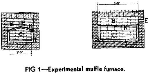
level of liquid metal at not over 2 in. in depth. Even with this small depth of metal, serious leakage occurred.
At about the same time, a pilot unit was constructed which provided means for heating the metal bath from above and below. Heat was introduced below the bath by means of a gas flame within a refractory tunnel. This furnace leaked badly after every effort had been made to make it tight enough to contain molten die cast metal.
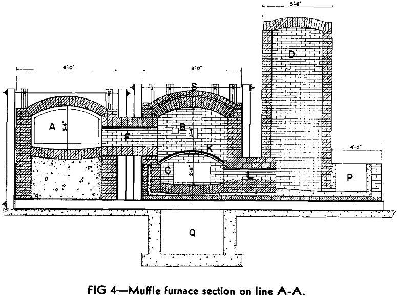
Shortly afterward a larger experimental unit 5 ft long with a carborundum arch 3 ft wide was built and tested. This unit is illustrated in Fig 1 which shows cross-sectional and longitudinal-sectional views of the furnace.
This pilot unit established the fact that zinc could be vaporized, practically, by means of a large shallow bath and that such vaporizing is less violent and more easily controlled than in the more restricted areas of small retorts.
Commercial Muffle Furnace
The first commercial unit, producing 5 to 7 tons of zinc oxide per day, was equipped with a vertical riser. This brick riser received zinc vapors from the vaporizing chamber and provided for contact of zinc vapor and air to produce zinc oxide. The zinc oxide was conveyed through a steel duct into a baghouse.
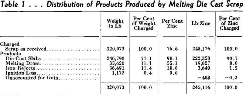
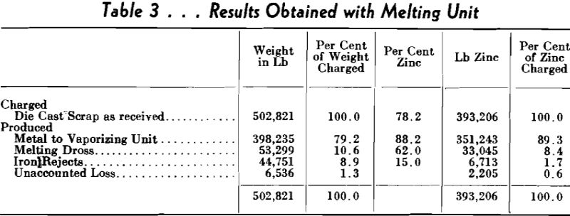
The melting unit now in use consists of a sloping hearth inclined toward a central point, which discharges into a trough to the vaporizing unit. With controlled melting unit temperatures, the oxidation of zinc is maintained at a minimum. The results obtained with this melting unit are shown in Table 3.
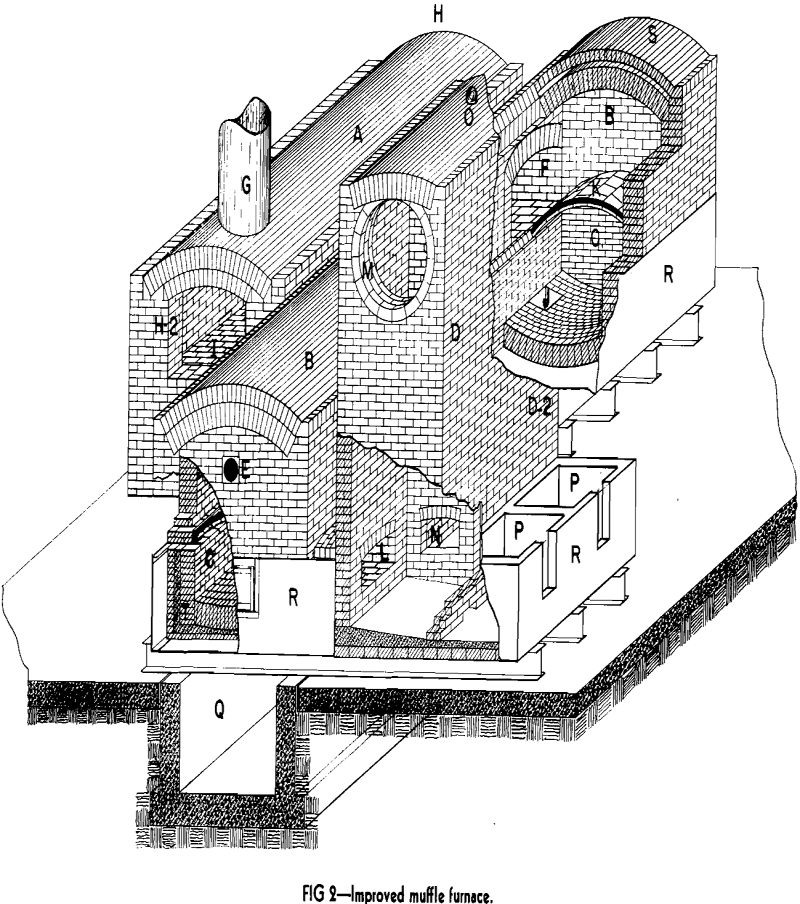
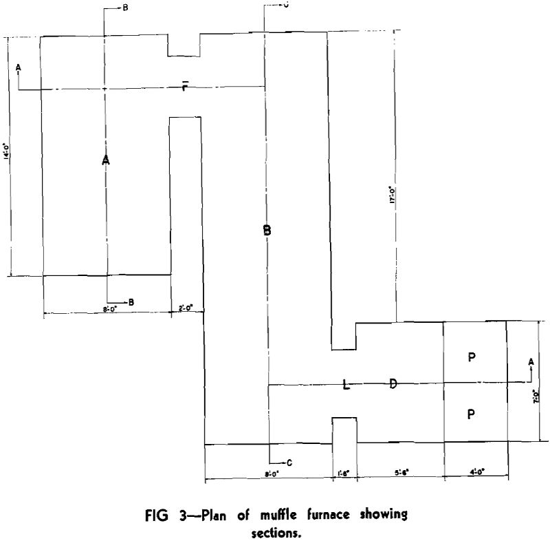
Muffle Furnace
Assembly drawing Fig 2 and sectional views (Fig 4, 5 and 6) along planes as indicated in the plan as shown in Fig 3 may be helpful in a more detailed study of the furnace design. The letters apply to Fig 1 to 6 inclusive.
A—Melting Unit
B—Combustion Chamber
C—Vaporizing Chamber
D—Riser
D2—Condenser
and provides for inspection of the bottom of the furnace pan.
Operating Procedure
The furnace is preheated with a gas flame, gradually raising the temperature to 1600°F. The oil burners are then started and the temperature of the combustion chamber elevated to 2400°F. Preheating requires about ten days.
Charging of metal is started at 2400°F and the production of zinc vapor begins almost at once. Charging is continued at as rapid a rate as possible until a depth of 5½ in. of metal has accumulated in the vaporizing unit.
Conditions which determine the end of the cycle are: The rate of zinc vapor production for economical operation of the furnace, a low zinc content in the residue metal, as tapped from the furnace, and a lead content low enough to meet the requirements of the particular zinc oxide being produced.
The cycle is ended by tapping residue metal from the vaporizing chamber, emptying it as far as possible. This metal is drained through a tap, not shown, into cast iron molds. The temperature of the furnace is held constant while it is being drained.
Production of Zinc
Of the various types of risers tried at East Chicago, several of them indicated the possibility that zinc metal could readily be produced from the muffle furnace. The relative position of the riser with respect to the molten bath of metal in the vaporizing unit seemed ideal to exclude or at least reduce contamination of the zinc metal by copper, aluminum and tin.
Zinc Produced from Secondary Metal
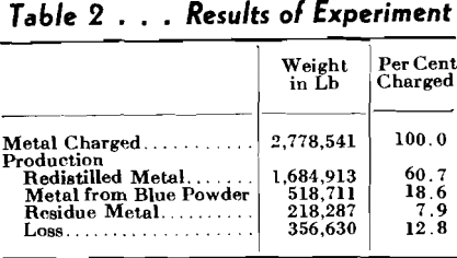
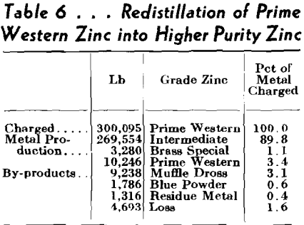
With this type of riser on the furnace, the distillation of zinc from secondary metals became a commercial possibility because the zinc produced in test runs was Prime Western, Brass Special or Intermediate grade. The results of such an experimental run are given in Table 5. In this run die cast slabs and die cast scrap were used as the source of zinc.
.

More
This particular model has a chamber size of 12 inches high, 14 inches wide and 18 inches in length. These are versatile models and offer inexpensive means of bringing your heat treating in-house; ideal for most tool room applications because they combine a high temperature hardening chamber stacked above a tempering or draw oven.
Heat treating most of your common tool steels involves a 3-step process of first hardening the steel at high temperature in the furnace chamber under radiant heat. Typically, this is done in the 16-1900 degree temperature range. After the hardening, the parts will be removed and they’re quenched in either air, oil or water. After the quench cycle, the parts are loaded into the oven chamber to remove the hardness out of the steel at low temperature under convection heat. The oven is equipped with a fan assembly to recirculate the air which is critical for achieving uniform heat at low temperatures.
Our models feature heavy gauge coil wound heating elements, mounted in removable panels on the side walls. The chambers are lined with a hot faced fire brick layer backed up with a mineral wall for great heat storage. The floor of the chamber has a hard plank to support the work load and protect the floor insulation. The doors on the furnace models are a horizontal swing type for quick operation. A micro switch shuts off the heating elements when the door is open. Both chambers operate independently using digital temperature controls. The furnaces are completely wired and assembled and test fired and we ship directly to your plant.
These models are compact, easy to install and operate. Bringing your heat treating in-house will save you money by eliminating the live charges from your commercial heat treater, will save on your turnaround time and help maintain better control on your production schedule.
Today we want to talk about economy box furnaces. These models offer an inexpensive means of bringing your heat-treating requirements in-house. The models are rated for operation up 2200 degrees Fahrenheit under air, and ideal for hardening small parts and processing light loads. When combined with foil wrapping of tool steels, a scale 3 finish can be achieved. Most parts will have a dull gray finish with hardness to the surface.
The models feature heavy-gauge coil wound heating elements with a low Watt loading for longer element life. The elements are mounted in removable holders on both side walls. The chamber is lined with a combination of a fire brick hot face, with a backup layer of mineral wall for better heat storage and low outside shell temperature. A hearth plate on the floor of the chamber supports the workload and protects the floor insulation. A horizontal swing door with a cam latch provides a tight, brick to brick seal and a microswitch automatically shuts off all power to the heating elements when the door is open.
All models are standard equipped with a Honeywell digital temperature controller. The furnaces are completely wired, assembled and shipped directly to your plant, ready for connection to your main power supply. These particular models are also equipped with a ten recorder and a fusible disconnect switch. Additional accessories are available, including high-limit safety systems, programmers, timers and various door arrangements. These models are compact, easy to install and operate. Bringing your heat treating in-house will save you money by eliminating minimum life charges from your commercial heat treater, save on turnaround time, help maintain better control of your production schedule and improve the quality of your product.