
Hover
")
Hover

Hover

Hover

Hover
")
Hover
")
Hover
")
Hover
")
Hover
")
Hover

")


")
")
")
")
")
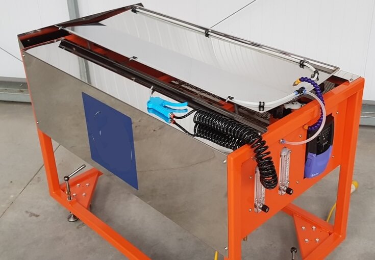
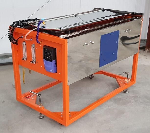
Multi Gravity Mozley Separator Drum
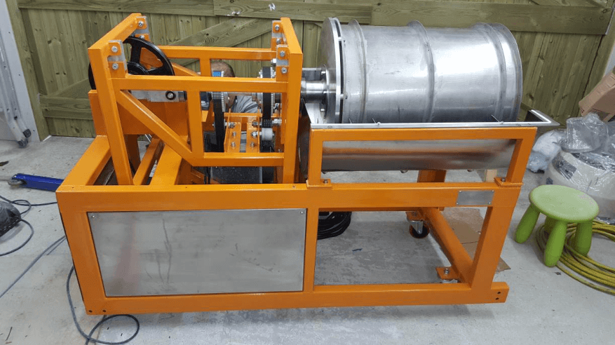
The 911MPEC900 Laboratory or Pilot plant multi-gravity separator (MGS) is a compact and mobile unit suitable for laboratory or on-site pilot plant investigation into the continuous separation of minerals of different specific gravities in liquid suspension.
It is able to separate two minerals from each other or separate a group of heavy minerals from lighter “gangue” material, provided that there is a reasonable difference in specific gravities.
The MGS is suitable for the treatment of fines and ultrafines with a maximum particle size of approximately 150µm (0 .15mm) and lower limit of approximately 5µm (0.005mm).
Typical applications include
- the scavenging of precious metals or valuable minerals from tailings or slimes streams
- pre-concentrating heavy mineral sands or industrial minerals (anatase, barytes, chromite, coal etc.)
- upgrading flotation concentrates, concentrating base metal oxides, sulphides, uranium etc. from primary ores
- treatment of alluvial ores in general

Description
The Laboratory multi-gravity separator (single drum design) formally known as the Richard Mozley C-900 (MGS–C-900). We are also please to offer the new “Pure Select” system in addition to the conventional scraper system.
The (MGS–C-900) uses the same principles of separation and mechanical techniques as the larger double drum MGS C-902 with 3.5 to 4 tons per hour capacity and we confirm that the performance of the (MGS–C-900) laboratory machine will be equal to that obtained from the larger field MGS C-902, assuming the same feed and equipment set-up.
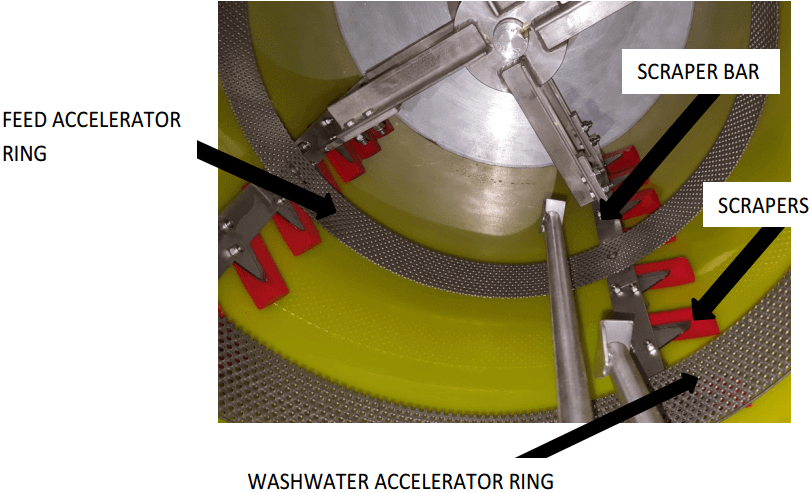
The (MGS–C-900) is a premium separator designed to separate and upgrade the finest minerals and metals on specific gravity difference. The optimum feed to the (MGS–C-900) machine will typically comprise solids in the range of 5 to 120 microns. It uses a similar principle of separation as a shaking table but enhances the degree of separation and the capacity of the machine multiple times by wrapping the normally horizontal separating surface of a shaking table into a conical drum. When rotated this develops a force many times greater than gravity alone causing the finest particles to separate within the dynamic thin liquid film coating the inner surface of the drum. The speed of rotation and degree of shake can be adjusted to provide a high degree of selectivity in operation, enabling the (MGS–C-900) machine to achieve the required grade and recovery of concentrate to meet the client’s needs. Internal scraper blades convey the heavy concentrate to the front of the drum, while lighter material is washed to the back of the drum as a tails stream.
The MGS consists of a slightly tapered open ended drum that rotates clockwise (as viewed from the open end) while being shaken axially with a sinusoidal motion. Inside the drum is a scraper assembly that rotates in the same direction as the drum but at a slightly faster speed.
Feed slurry is introduced continuously from a position midway along the drum onto its internal surface via an accelerator ring launder. Washwater is added via a similar launder positioned near the open end of the drum.
As a result of the high centrifugal forces and the added shearing effect of the shake, the dense particles migrate through the slurry film to form a semisolid layer against the wall of the drum. The scrapers move the dense layer towards the open end of the drum where the layer discharges into the concentrate launder.
The wash water carries the less dense minerals downstream to the rear of the drum to discharge via slots into the tailings launder.
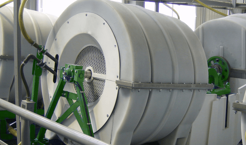
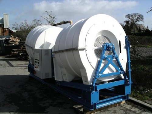
For full-scale production the 911MPEC902 Double Drum MGS is available. Extensive trials have demonstrated that this unit, measuring 4.7m x 1.5m x 1.8m high, will produce similar grade and recovery to the 911MPEC900 MGS while treating between 10 and 25 times the feed tonnage.
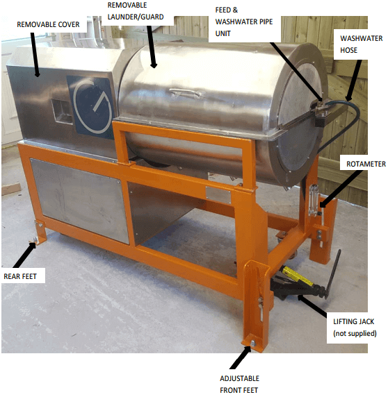
General Arrangement of this Mozley Drum
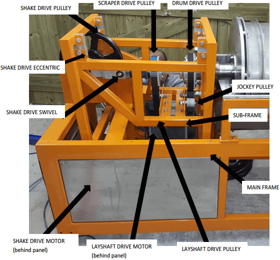
Mozley Drum’s Mechanical Arrangement
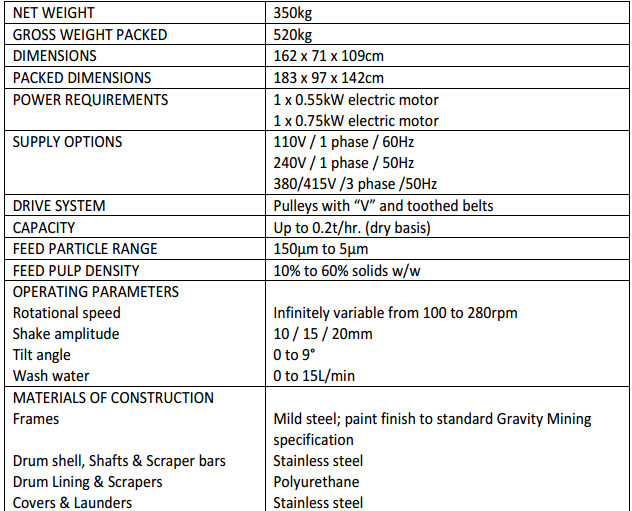
Specifications of the Mozley Drum
Initial Setting Up of the Mozley Drum
Lifting & Handling
Use forklift truck or similar mechanical aid to lift equipment from the underside of the main frame at the indicated positions.
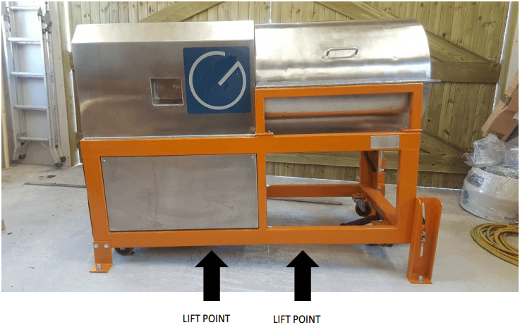
CAUTION: DO NOT LIFT BY, OR USE ANY UNNECESSARY FORCE ON THE DRUM
The MGS is fitted with castor wheels and can be easily moved on a flat surface.
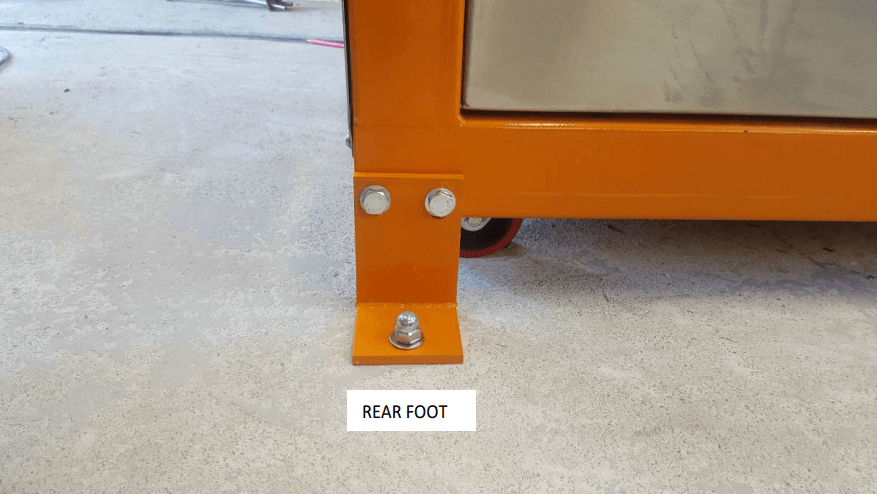
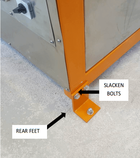
Bolting Equipment to Floor
- Position the MGS on a level concrete floor.
- Using two 19mm spanners slacken the bolt securing each rear foot in the raised position.
- Swing the feet into the position shown (this will take the weight of the castor wheels).
- Fit the second nut and bolt provided for each foot. Leave these nuts finger tight until tilt angle has been set.
- Use a 12mm masonry drill bit to make a hole in the floor corresponding with the holes provided in the feet.
- Use anchor bolts to secure the two rear feet to the floor as shown.
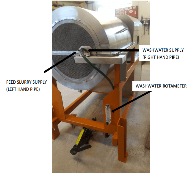
Feed Arrangement – Continuous Feeding
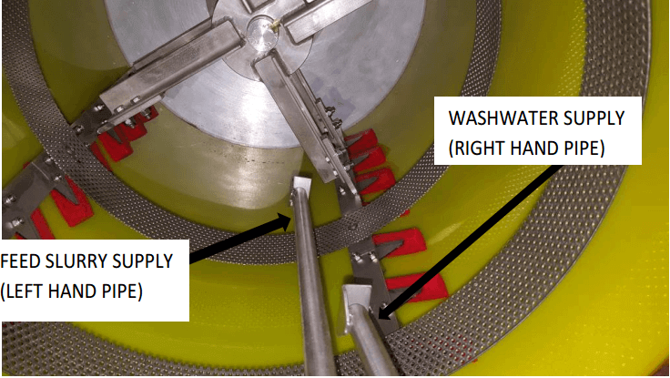
Where a continuous supply of feed slurry is available, or the feed is supplied via a pump from a stirred tank, connect a hose of suitable size (12.5mm ID), fitted with a control valve if necessary, from the feed supply to the left hand pipe on the feed/wash pipe unit.
Washwater
Before dispatch the rotameter is fitted with a plastic packing strip to prevent breakage of the glass tube by the metal float during transit.
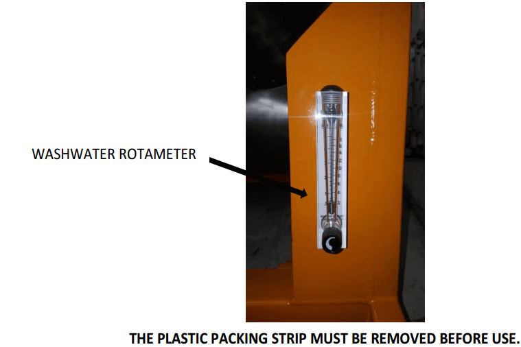
- Remove front cover of rotameter
- Pull out clip retaining top plug
- Ease top plug out of glass tube
- Remove packaging material
- Reassemble rotameter
- Connect a 12.5mm hose from water supply to the lower rotameter inlet position
- Connect wash-water hose (the longer length of hose supplied) from the rotameter outlet to the right hand pipe on the feed/wash pipe unit)
Electricity Supply
Connection of electricity supply must be done by a competent electrician. Connect the electricity supply to the isolator fitted at the rear of the machine. Check motor rating plates to confirm correct electricity supply.
Important:
- Do not operate machine before carrying out checks described in section 5.
- Drum rotation must be clockwise when viewed from the open end.
- The electrical enclosure and inverter are set during commissioning and do not contain ‘user’ adjustable controls.
Initial Test Running
Inspection
- Disconnect the electricity supply
- Remove the four locating screws from the launder/guard
- Carefully remove the launder/guard
- Carefully inspect the inside of the drum to ensure there are no loose objects or components that may interfere with the drum’s rotation or oscillation
- Ensure the scrapers are fitted non-rigidly to the four scraper bars at an angle of 60° to the drum axis
- Rotate the drum by hand over several revolutions in a clockwise direction (NEVER anticlockwise) when viewed from the open guarded end. This ensures that the drum and scrapers rotate freely and that all scrapers are undamaged and in the correct position.
- Replace launder
- Replace the four locating screws to the launder/guard
- Remove the four locating screws from the rear cover
- Remove the rear cover
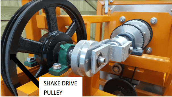
- Rotate the shake drive pulley by hand to ensure the drum and shaft assemblies oscillate freely.
- Replace rear cover
- Replace four locating screws to the rear cover
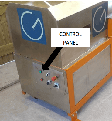
 Electrical Controls
Electrical controls are mounted on a panel at the rear of the machine. The electrical enclosure and inverter are located within the body of the MGS and must not be adjusted by the user. The settings are adjusted during commissioning by a qualified person. For information the Lenze SMV frequency inverter manual is supplied as an addendum.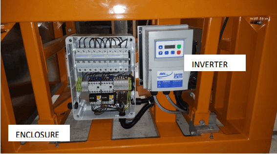
 Test Running
Ensure Electricity Supply is Disconnected
- Remove the lower side panels,
- Remove tension from layshaft drive belt by slackening clamp bolt on layshaft drive motor mounting plate.
- Remove belt from motor pulley
- Reconnect electricity supply
- Switch isolator to ‘ON’ position
- Switch on rotary drive
- Ensure the motor rotates in the direction indicated by the arrow
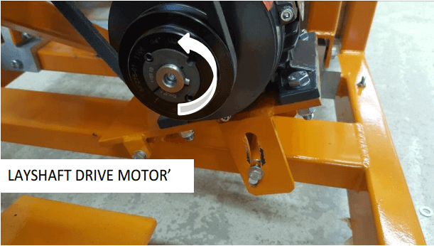
 The Drum must Rotate Clockwise when Viewed from the Open Guarded End
If the Drum Rotation is not Correct Press Stop Button
- Isolate the machine from the electricity supply
- Arrange for a competent electrician to reverse polarity of connections at the isolator.
- Reconnect to the electricity supply
8. Refit belt to motor pulley
9. Set correct tension to layshaft drive belt
10. Tighten clamp bolt on layshaft drive motor mounting plate
11. Fit lower side panels
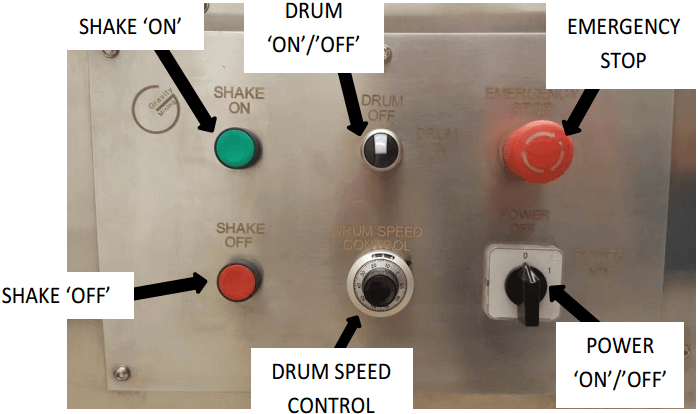
12. Check shake mechanism operates satisfactorily by pressing shake ‘ON’ button
13. Switch off using either stop button and switch or the isolator
Note: Multi Gravity Separator must not be used without Wash-water. this ensures lubrication of the scrapers.
Multi Gravity Separator Operating Variables
Tilt Adjustment
The machine is fitted with sliding feet which are adjusted as follows:
- Slacken the four bolts securing the two rear feet to the MGS using two 19mm spanners. These feet are already bolted to the floor.
- Slacken the four bolts securing the two front feet using two 19mm spanners
- Raise the front of the MGS to the required height using a jack or a lever at the jacking point indicated
- Slide the feet to the required position
- Re-tighten rear feet and sliding feet bolts
In practice a tilt angle of approximately 4° is usually found to be satisfactory for feed solids finer than 250µm
A combination of larger tilt angle with faster rotational speed will usually produce higher concentrate grades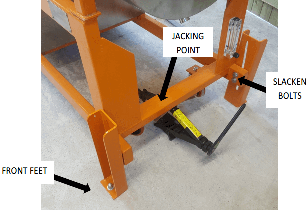
Rotational Speed of an MGS
The rotational speed of the drum is controlled by a variable speed controller mounted below the layshaft, accessible on removal of the right hand panel. Speed is adjustable between 100 and 280 rpm using the rotary speed control (this is a ten turn potentiometer) mounted on the control panel.
As a factory setting the speed control is set to give (for a 240v 50Hz supply):
| RPM | reading |
| 100 | 000 |
| 150 | 275 |
| 200 | 555 |
| 280 | 999 |
These figures are correct where the electrical supply is 240 volts 50Hz. Calibration will vary with voltage frequency. On installation check the drum speed over a range of settings and if necessary plot a revised calibration chart similar to the one below.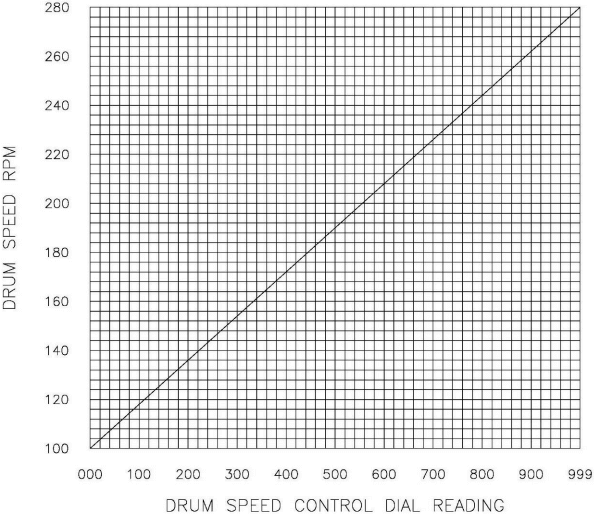
Shake Frequency of a Mozley Separator 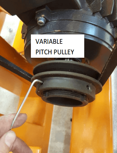
Adjust shake frequency by adjusting the variable pitch pulley using the 4 Allen screws.
How To Change Shake Frequency of the Drum
- Disconnect Electricity Supply
- Remove cover and lower side panels.
- Slacken the Allen screws on the variable pulley adjustable flange
- Screw the adjustable flange to reduce the distance between both flanges and therefore increase the ‘V’ belt tension and the shake speed
- Unscrew the adjustable flange to increase the distance between both flanges and therefore decrease the ‘V’ belt tension and the shake speed
- Use trial and error to adjust the shake speed
- When satisfied with the shake speed, tighten the Allen screws to lock the flange in position
- Replace covers
- Re-connect to electricity supply.
The variable range is 52 to 78 pitch diameters
In Practice it is Usually Unnecessary to Change the Shake Speed from the Factory Setting.
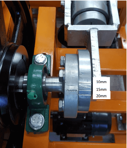
Amplitude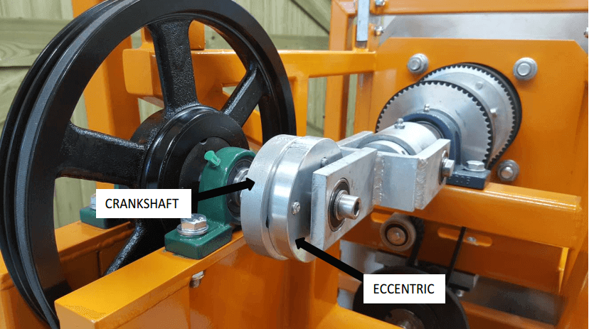
Use the variable eccentric to adjust the amplitude of shake.
The options available are
- 10mm
- 15mm
- 20mm
 How To Change the Amplitude the the Mozley Drum
- Ensure Electricity Supply is Disconnected
- Remove cover
- Using 17mm spanner, slacken the three bolts securing the eccentric to the crankshaft
- Prevent crankshaft rotation by holding tightly.
- Rotate eccentric until the amplitude setting on the eccentric aligns with the mark on the crankshaft
- Tighten the three bolts securing the eccentric
The factory setting of amplitude is 15mm in practice a small amplitude is usually used with a higher shake speed and vice versa
Washwater
Washwater flowrate is adjustable between 0 to 10 L/min by means of the thumb valve below the rotameter.
The quantity of washwater required will normally depend on the density of the minerals treated. For lower SG minerals a flowrate of 2L/min may be sufficient whereas for high SG minerals a flowrate of ≥ 6L/min may be required.
Increased washwater gives a cleaner concentrate (dense fraction), but also results in increased loss of dense mineral to tailings. Solids of lower specific gravity (such as barytes) usually require less wash water than materials with higher specific gravity (such as cassiterite) or coarse solids.
Feed Rate
Depending on the nature and particle size of the feed solids, throughput may vary between 50 and 200kg/hr. of dry solids. For finer solids (<75µm) an acceptably clean concentrate with good recovery is usually produced with a throughput of 100kg/hr.
As a general guide use feed pulp density of 40% w/w with a flowrate of 2 L/min.
Important: do not exceed a feed rate of 200kg/hr. of solids.
Overloading may damage the drive belts
Feed pulp density & classification
Feed pulp density may be varied between 15% and 50% solids w/w. The higher pulp density feeds will require additional washwater. It is usual to use a pulp density of 30% solids w/w.
As with any gravity concentrator a deslimed or classified feed is always preferable. Undeslimed, low density feeds will require higher rotational speeds and vice versa.
Heavy Duty Scrapers
When treating high density minerals at high concentrations (for example magnetite concentrate) it is necessary to fit heavy duty scrapers. These are available upon request.
Multi Gravity Mozley Separator Drum Test Procedure
Simulated Continuous Testing
The MGS is a continuous processing separation machine and in order to achieve an accurate indication of its true performance it is preferable to use a test procedure which more closely simulates continuous operation. For this a minimum of 10kg of sample solids is required per test.
Proceed as follows:
- Carry out initial setting-up procedure- see Section 4
- Start with the following settings :
| Tilt | 4° |
| Rotational Speed | 200rpm (mid-range) |
| Shake Speed | 4.8cps (mid-range) |
| Amplitude | 15mm (mid-range) |
| Washwater | 3L/min |
3. Carry out initial test running procedure- Section 5
4. Isolate From Electricity Supply
5. Loosen and remove four set screws
6. Remove upper launder
7. Using a water hose, thoroughly wash out all compartments and drum, ensuring that no residue remains from previous test runs.
8. Replace launder
9. Re-connect to electricity supply.
10. Place a sample bucket under the tailings discharge pipe, another under the concentrate discharge pipe and a third under the centre spillage discharge pipe.
11. Mix a minimum of 10 kg of dry sample with water to give a pulp with a density of between 30 to 50% solids w/w (volume will be 28 and 14 litres respectively). To ensure adequate dispersion of the solids it is advisable to add a dispersing agent (i.e. Sodium Polymetaphosphate). Ensure all lumps or agglomerates are fully dispersed. The solids must be kept in homogeneous suspension for the duration of the test using a mechanical stirrer.
Stir the feed pulp vigorously to keep all particles in suspension.
12. Open the water valve below the rotameter and adjust to give a washwater flowrate of 3L/min.
13. Reconnect to electricity supply and switch on isolator.
14. Press shake starter button and switch on rotary drive to set the MGS in operation.
15. Set speed control to 555 (to give 200rpm). Leave the settings for shake speed and amplitude unaltered for the initial series of tests. Set tilt to approximately 4°. Optimise the results by varying the settings (by trial and error) in subsequent test series. Keep settings for shake, amplitude and tilt angle constant in a test series while varying rotational speed and washwater flowrate.
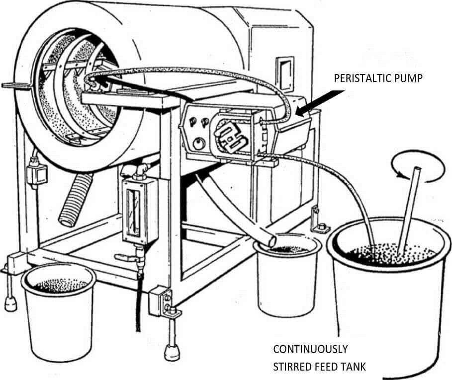
16. Using a suitable pump (a peristaltic type is recommended) introduce the feed pulp into the MGS at a steady feed rate of 1 to 2 L/min.
17. Allow the MGS to run under steady feeding conditions until operation becomes completely stabilised. This usually takes between 2 and 5 minutes, depending on the nature of the sample and the grade of the heavy mineral present. Check buckets frequently and replace when they become full.
18. When conditions have become stabilised use clean buckets to simultaneously collect timed samples of concentrate and tailing products. Allow sufficient time to collect a reasonable quantity of concentrate (this may have a very low flowrate). Between 10 and 30 seconds is normally adequate.
19. After collecting the test products turn off the feed and allow the MGS to operate until the bulk of the remaining solids have discharged, either to drain or into the original buckets.
20. Turn off the washwater and stop the MGS.
21. Isolate From Electricity Supply
22. Remove upper launder.
23. Using a water hose wash all remaining solids from the launders and drum (inside and out) either to drain or into the original buckets. Rotate drum by hand while washing out to ensure removal of all solids.
24. The two samples required for full evaluation of the test will consist of
| CONCENTRATE OR DENSE FRACTION | Scraped or conveyed product collected over a timed period via front launder with the MGS running in a stabilised condition |
| TAILINGS | Product containing low density solids collected over the identical timed period from the rear launder. |
Note: Any spillage collected from the centre spout should be combined with the concentrate sample.
25. Dry, weigh and analyse the samples (see Section 8).
All Other Samples May Be Discarded.
Carry out several tests using different operating settings, to optimise performance.
It is not necessary to vary tilt, shake frequency or amplitude. As a guide, adjust rotational speed and/or washwater as follows:
| TOO MUCH CONCENTRATE PRODUCED | Reduce speed and/or increase washwater |
| INSUFFICIENT OR NO CONCENTRATE PRODUCED | Increase speed and/or reduce washwater |
 Recommended Arrangement For Continuous Testing
Interpreting the Laboratory Multi Gravity Separator Drum Test Results
Procedure
Interpretation of test data will vary depending on the sample and will, of course, vary with the amount of information required.
Use the following procedure
- Remove excess water from the test products. This may be achieved either by filtering or by allowing all solids to settle, then decanting or siphoning off the clear water.
- Transfer the damp solids to enameled steel or stainless steel trays, using a small amount of water from a wash bottle to ensure that all solids are recovered from the buckets.
- Dry the samples in an oven at a temperature of approximately 100°C.
- Allow to cool.
- Weigh the dried samples carefully
- Assay for the element or mineral of interest.
- Calculate grade and recovery data in the conventional manner.
Typical Test Sheet

Maintenance of the Mozley Drum
Carry out regular maintenance as part of a planned maintenance system.
- Always check and if necessary adjust the drive belt tension. (Section 9.1)
- Inspect all bearings and seals. (Section 9.2)
- Lubricate all bearings (Section 9.3)
- Tighten all nuts & bolts
- Inspect drum and scrapers for signs of wear
Drive Belts
- Tension drive ‘V’ belts by slackening the motor mounting plate clamp bolts, pressing down on the motor and re-tightening the clamp bolts
- Tension timing belts by adjusting the positions of the three jockey pulleys
Belts used are as follows (also see 9.2)
| Rotational Drive ‘V’ belt | SPZ 1060 |
| Shake Drive ‘V’ belt | SPZ 1737 |
| Drum Drive Belt | 390 L100 |
| Scraper Drive Belt | 367 L100 |
Bearings, Seals & Drive Belts
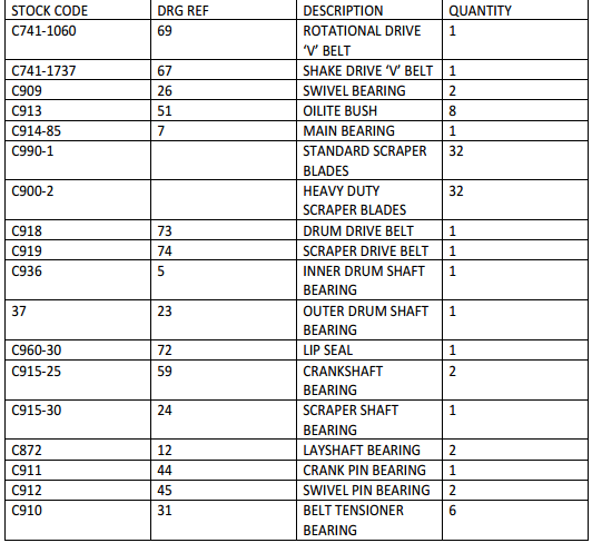
Check all bearings, seals and drive belts at regular intervals and change if necessary. When ordering replacement parts pleas use stock code numbers shown on Page 35.
Lubrication
Apply grease at regular intervals to nipples on Pillow Blocks and swivel bearings using a snap-on grease gun.
Use a general purpose lithium based grease for all lubrication purposes.
Motor bearings and all other bearings are sealed units with sufficient lubricant for life.
Troubleshooting a Multi Gravity Separator
Mgs Vibrates or is Unstable in Operation
- Check if rear feet bolts (to floor/frame) are loose. Tighten if necessary
- Check if front feet bolts are loose. Tighten if necessary.
- Check if a font foot is not in contact with the floor. Readjust if necessary.
Little or no Concentrate Produced
- Check if rotational speed is too low. Increase speed.
- Check if washwater flowrate is too high. Reduce flowrate.
- Check if tilt angle is too steep. Reduce angle.
- Check if shake intensity is too high. Reduce shake frequency and/or amplitude.
- Insufficient quantity of feed solids and short feeding time. If there is no conveyed product (concentrate) the material remaining on the drum inner surface at the end of the wash period may (as an approximation) be considered to be the concentrate. Under normal continuous running conditions only tailing and concentrate are produced.
- Loose or broken scrapers. Re-fit or re-new.
- Loose or broken drive belts. Tighten or re-new
Do Not Overfeed The Mgs Or The Driving Belts Will Break.
Little or no tailing produced (i.e. Too much concentrate)
- Rotational speed too high. Reduce speed.
- Washwater flowrate too low. Increase flowrate.
- Tilt angle too shallow. Increase angle.
- Shake intensity too low. Increase shake frequency and/or amplitude.
Shake Not Operating
- Loose or broken drive belt. Tighten or re-new.
- Check shake drive and transmission system.
List Recommended Multi Gravity Mozley Separator Drum Spare Parts
Multi Gravity Separator - Mozley Drum VIDEO
Multi-Gravity Separator (MGS)
The MGS combines the centrifugal motion of an angled rotating drum (though not at such a high speed) of a Kelsey jig or Falcon Concentrator, with the oscillating motion of a shaking table, to provide an enhanced gravity separation, particularly suited to fine particles.
The principle of the separation in the MGS is based upon the above-mentioned forces that act on particles in a slurry stream being fed and are distributed onto the inside of the drum’s surface. With the aid of scrapers and wash water, the high SG particles migrate up the drum to discharge over the drum’s top lip, while the low SG particles flow in the opposite direction and discharge over the lower drum lip (Fig. 8).
Operating Variables
- Drum rotational speed or spin (increased spin enhances the centrifugal G force imparted to the particles, making it more difficult for the particles to move up the drum, hence resulting in a smaller weight take and a cleaner concentrate
- Drum stroke length and frequency (increased length and frequency within limits will tend to increase the forces moving the particles up the drum, resulting in a greater weight take and a lower grade of concentrate)
- Drum wash water will increase the washing of the slurry particles as they try to move up the drum, thus producing a cleaner concentrate
- Drum tilt angle (increased tilt will produce a cleaner concentrate)
Advantages
- Very selective separation with fine-sized particles (typically -75 + 10 microns)
- High upgrading ratios (typically 20 to 1)
Disadvantages
- Low capacity for surface area and space, although larger capacity (and physically bigger) machines are now available
- Mechanically quite complex and expensive
- Generally enclosed so unable to see separation surfaces
- Requires reasonable amount of operator attention
- Unsuited for treating coarse material (feed must be screened)
Beneficiation of Chromite Concentration Waste By Multi-Gravity Separator And High-Intensity Induced-Roll Magnetic Separator
With more mining activity, the amount of waste materials readily increases in some countries. Storage of waste materials or tailings disposal has become a serious matter for the mining industry due to its growth. During the earlier concentration of valuable minerals in many plants, large volumes of tailings were produced and these tailings may be harmful to the environment (Ozkan et al, 2002). Therefore, it is important for some tailings to be investigated for both economic and environmental reasons in many countries.
Chromite is an important mineral used in metallurgy, chemistry, and refractory industries. Chromite ores contain a variety of gangue minerals such as serpentines and olivine. Therefore, some kind of concentration is required for beneficiation of chromites. The most commonly used beneficiation methods for chromite ores are the gravity methods, such as shaking table, jig, spiral, and Reichert cone. Magnetic separation is also used depending on the ore characteristics. Flotation is also used for the beneficiation of finely grained ores. With these conventional methods depending on the liberation particle size of the ore, significant amounts of fine chromites are lost to the tailings. For this reason, all of these methods are only partly successful in the fine particle size range (Gence, 1999).
Many investigators have reported the remarkably high value of chromites in the tailings of chromite concentration plants. A number of investigations have been run to determine the most economic process applicable to the fine tailings of Turkish concentration plants (Guney et al., 1999; Guney et al., 2001; Cicek et al., 2002; Ozdag et al., 1993).
There are approximately 2,700,000 tons of chromite tailings disposed containing approximately 20.7% Cr2O3 in the tailing dam of the Guleman-Sori/Turkey chromite concentration plant (Gence, 1999; Kaya, 2002). Conventional gravity separation devices usually lose efficiency in the finer size ranges. The multi-gravity separator is a concentration device designed to use several of the traditional gravity concentration techniques in one machine, allowing a separation of finer materials or materials with much closer specific gravity than any of the traditional methods (Chan et al., 1991; Chan et al., 1993; Goktepe, 2005). Typical applications of MGS include the scavenging of valuable metals or valuable minerals from tailings or slime streams; pre-concentration of heavy mineral sand or industrial minerals; upgrading flotation concentrates; concentrating base metal oxides, sulfides, and uranium from primary ores; and treatment of alluvial ores in general (Chan et al., 1991; Chan et al., 1993). The MGS has also been reported to have the potential to be a useful machine in the decontamination of fine metal minerals from abandoned mines, leaving a tailing with much reduced metal availability where conventional mineral processing techniques are not suitable (Wise et al., 1997; Traore et al., 1995). It was also reported that beneficiation of fine size celestite tailings by MGS is possible (Aslan et al., 1996).
In this study, the applicability of an enhanced gravity concentration technique and magnetic separation for beneficiation of fine chromite from the magnetic tailings of the Guleman-Sori/Turkey chromite concentration plant was investigated by using a multi-gravity separator and high-intensity induced-roll magnetic separator.
Materials and Methods
Multi-Gravity Separator (MGS)
The multi-gravity separator (MGS) concentrates particles based on the combined effects of centrifugal acceleration and forces acting on a conventional shaking table. The laboratory/pilot plant scale C-900 MGS consists basically of a slightly tapered open-ended drum measuring 600 mm long with a diameter of 500 mm that rotates in a clockwise direction and is shaken sinusoidal in an axial direction. Inside the drum is a scraper assembly that rotates in the same direction but at a slightly faster speed (Chan et al., 1991; Chan et al., 1993; Aslan et al., 1997; Aslan et al., 1997; Ozbayoglu et al., 2002; Bhaskar et al., 2002; Patil et al., 1999). Feed slurry is introduced continuously midway onto the internal surface of the drum via a performed ring. Wash water is added via a similar ring positioned near the open end of the drum. As a result of the high centrifugal forces and the added shearing effect of the shake, the dense particles migrate though the slurry film to form a semi-solid layer against the wall of the drum. The scrapers convey this dense layer towards the open end of the drum where it discharges into the concentrate launder. The less dense minerals are carried by the flow of wash water downstream to the rear of the drum to discharge via slots into the tailings cleaner (Ozbayoglu et al., 2002; Bhaskar et al., 2002; Patil et al., 1999).
The parameters affecting the efficiency of separation on MGS are the drum speed (infinitely variable from 100 to 300 rpm), wash water (0 to 10 l/min), inclination (0° to 9°), shake amplitude (10/15/20 mm), shake frequency (4.0/4.8/5.7 cps), and pulp density of the feed slurry (10% to 50% by weight)(Aslan et al.,1996).
High-Intensity Induced-Roll Magnetic Separator (HIRMS)
The Carpco Model MIH 111-5 is a laboratory/pilot-plant dry high-intensity magnetic separator designed to separate moderately or weakly paramagnetic materials. This magnetic separator is also called a high-intensity induced-roll magnetic separator (HIRMS).
High-intensity induced-roll magnetic separator treats from 1 mm down to 74 µm in size and boasts a capacity of up to 90 kg/h based on material having a bulk density of 1600 kg/m³, variable magnetic field intensity up to 0.96 T, 127 mm diameter and 50.8 mm length laminated roll with variable speed 0-100 rpm (Ibrahim et al., 2002).
The separator places all materials in contact with the highest magnetic field at the zones of steepest magnetic gradient and utilizes magnetic force and gravity to capture weak magnetic particles. A turning induced magnetic roll is used to transport materials through the active area providing an opposing centrifugal force for separation of magnetic and non-magnetic materials. This technique is capable of efficiently removing weak magnetic materials as contaminants in non-magnetic products.
Materials
The sample used in tests was taken from the tailings dam of the Guleman-Sori/Turkey chromite concentration plant. The capacity of the plant was 6000 tons/year and the ore assays 30-33% Cr2O3. In the plant, a low-intensity and a high-intensity dry magnetic separator were used. The concentrate produced in this plant contains 42-43% Cr2O3. The chromite tailings disposed contain approximately 20.7% Cr2O3. The site was reported to have approximately 2,700,000 tons of chromite tailings disposed in the plant (Gence, 1999; Kaya, 2002).
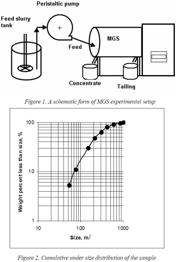
To determine the mineralogical characteristic, a physical/chemical analysis of the same sample was carried out by Gence. A complete chemical analysis by Gence is shown in Table 1 (Gence, 1999). A sieve analysis was carried out to determine the size distribution of the feed sample, as shown in Figure 2. Each size fraction was analyzed chemically and examined microscopically to determine the metal distribution and point of chromite particles, respectively. The results are shown in Table 2. The sample used in this study contains 20.7% Cr2O3. The sample is composed of chromite (mostly in 53-600 µm fraction) as valuable mineral, olivine (mostly in 25-275 pm fraction), feldspar (in 25-250 µm fraction), and pyroxenes (in 25-150 µm fraction).
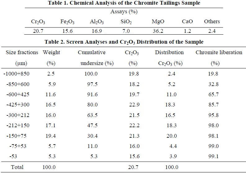
From the microscopic study, it can be easily seen that sufficient liberation, which is above 95%, can be reached at -300 µm particle size. Therefore, the sample was wet screened of 300 µm to obtain suitable feed size for MGS tests. The fraction coarser than 300 µm, which is too coarse to be handled by MGS, was ground to less than 300 µm particle size by ball mill.
Experimental Procedure
The batch tests were conducted in this investigation in The Mineral Processing Laboratory of Cumhuriyet University-Turkey. MGS tests were performed using the pilot scale machine, C900. A 10 l stainless steel cylindrical vessel was used for the feed slurry. The vessel was equipped with a turbine impeller agitator to mix the sample with tap water. The tap water used in experiments was of 7.3 pH and 18-20 °C temperature. 6000 cc of tap water was poured in the vessel and 2000 g of the dry sample was added for each MGS test. The water and the sample were agitated at a low agitation rate by the impeller for homogeneous slurry in the vessel. A sample bucket under the tailing discharge pipe and another bucket under the concentrate discharge pipe were placed for MGS. Feeding was carried out by a peristaltic pump at a flow rate of 2.3 l/min in MGS tests. 2000 g of the dry sample for MSG tests and 1000 g of dry sample for HIRMS were used for each test. A schematic form of the MGS experimental setup is given in Figure 1.
Samples from the chromite concentrate and tailing streams were collected at steady-state conditions. These samples were filtered, dried, and weighed for analysis of grade-recovery. For each sample, 0.2 g was dissolved in 15 ml of the mixture of sulfuric and phosphoric acids (2:1 ratio) and then heated at 300 °C for 30 min. After dissolution, the solution was analyzed by the titrimetric method.
To produce final chromite concentrate from pre-chromite concentrate produced by MGS was de-slimed and dried before feeding to HIRMS.
Results and Discussion
In order to produce a saleable chromite concentrate from the magnetic tailings of Guleman-Sori/Turkey, at first stage, MGS tests were carried out to produce pre-chromite concentrate and to determine optimum operating conditions of MGS. In this stage, five operating variables of MGS were drum speed, wash water, inclination in degrees, shake amplitude, and shake frequency. The feed pulp density of 25% solid by weight and the feed flow rate of 2.3 l/min were kept at constants for MGS tests. The experimental conditions of MGS and test results obtained are presented in Table 3.
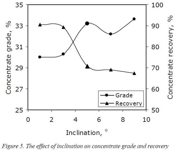
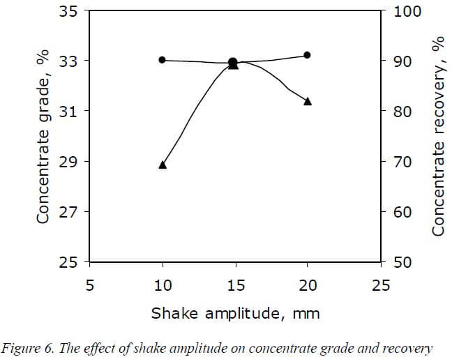
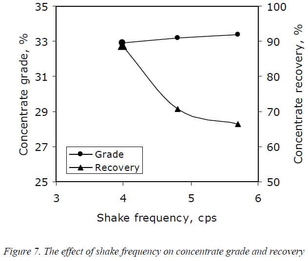
In order to gain a better understanding the effect of each parameter of MGS on the grade and recovery, data in Table 3 are presented graphically in Figures 3-7. Figure 3 shows the effect of drum speed on concentrate grade and recovery. As can be seen, a higher concentrate recovery can be achieved at a drum speed of 200 rpm. Figure 4 shows the effect of wash water on concentrate grade and recovery. A higher concentrate grade and recovery can be achieved at wash water of 4 l/min. Figure 5 shows the effect of inclination on concentrate grade and recovery. It can be seen that a higher concentrate grade and recovery can be obtained with an inclination of 5°. Figure 6 shows the effect of shake amplitude and Figure 7 shows the effect of shake frequency on concentrate grade and recovery, respectively.
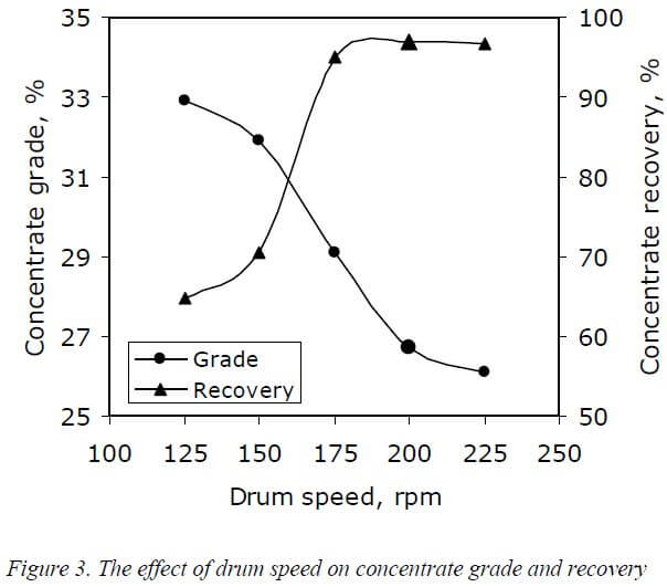
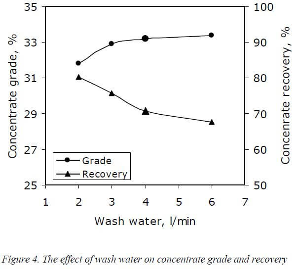
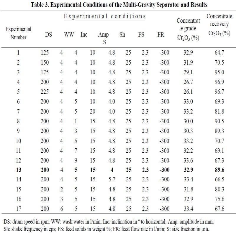
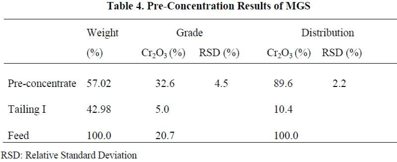
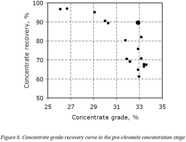
Common practice in most mineral concentration plants is to maximize the operating profit by driving the process towards an optimum grade-recovery point on a more or less known concentrate grade recovery curve. To find out optimum operation parameters of the MGS, a grade-recovery curve was plotted from Table 3 data and the curve is shown in Figure 8. From Table 3 and Figure 8, it can be easily accepted that a pre-concentrate containing 32.6% Cr2O3 with 89.6% recovery is a reasonable result to produce a final concentrate. As shown in Table 3 and Figures 3-7, the optimum operation parameters are as follows: drum speed of 200 rpm, wash water 4 l/min, inclination of 5°, shake amplitude of 15 mm, and shake frequency of 4 cps. Under these optimum conditions for producing pre-chromite concentrate, further MGS tests were performed 3 times under the same conditions. The mean results obtained are presented in Table 4. It can be seen from Table 4, the pre-chromite concentrate containing 32.6% Cr2O3 with 89.6% recovery could be produced at the optimum operation parameters determined.
The pre-concentrate consists of olivine, feldspar, and pyroxenes as gangue minerals. The pre-concentrate was screened to 75 µm, and then the -300+75 µm size fraction was fed into HIRMS to upgrade. On the other hand, the – 75 µm size fraction was considered as slime size.
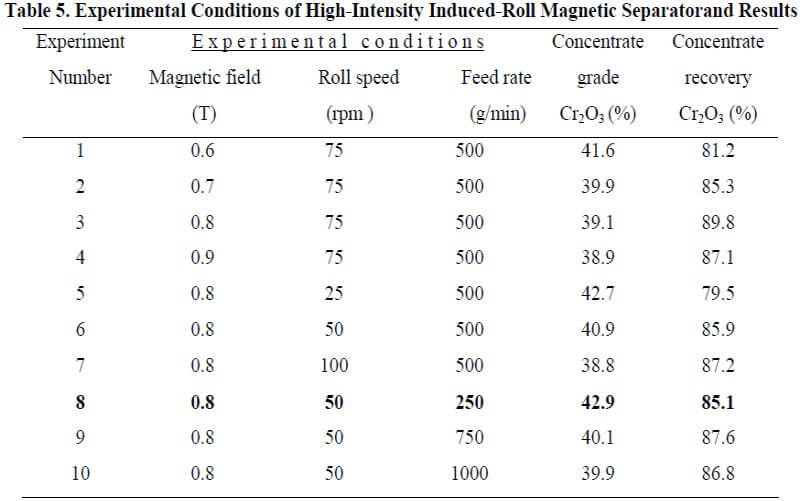
At the second stage, some optimization tests were also conducted to determine the optimum operating parameters of the HIRMS, which were magnetic field intensity (0.6-0.9 T), roll speed (25-100 rpm), and rate of feeding material (250-1000 g/min), on the metallurgical performance of the HIRMS both by qualitative and quantitative means. Experimental conditions of the high-intensity induced-roll magnetic separator and results obtained are presented in Table 5.
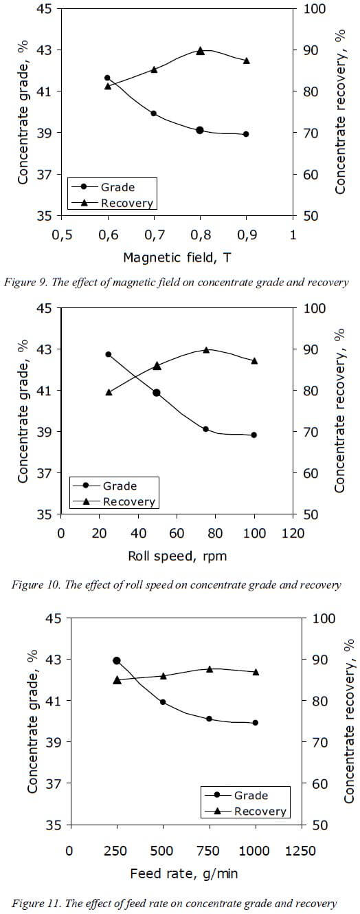
In order to gain a better understanding of the effect of each parameter of HIRMS on the grade and recovery, data in Table 5 are presented graphically in Figures 9-11. Figure 9 shows the effect of magnetic field on concentrate grade and recovery. Figure 10 shows the effect of roll speed and Figure 11 shows the effect of feed rate on concentrate grade and recovery, respectively.
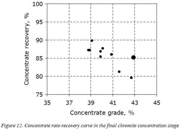
A grade-recovery curve for the final chromite concentration was also plotted from data in Table 5 and the curve is shown in Figure 12. In order to obtain the highest concentrate grade from the pre-chromite concentrate, as shown in Table 5 and in Figures 9-11, the optimum operation parameters of the HIRMS are as follows: magnetic field intensity of 0.8 T, roll speed of 50 rpm, and feed rate of 250 g/min. Under these operating conditions of the HIRMS, a final chromite concentrate containing 42.9% Cr2O3 could be obtained with 85.1% recovery.
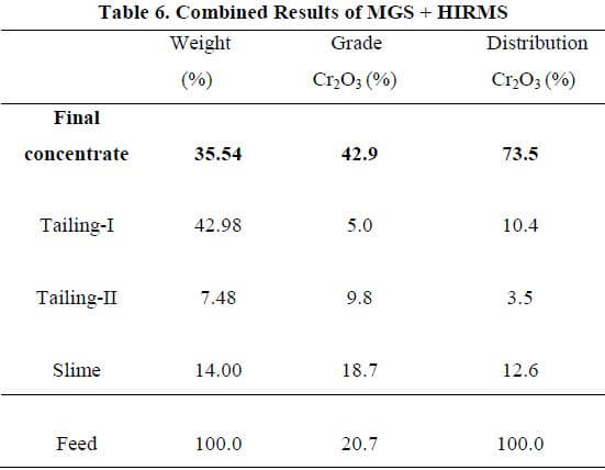
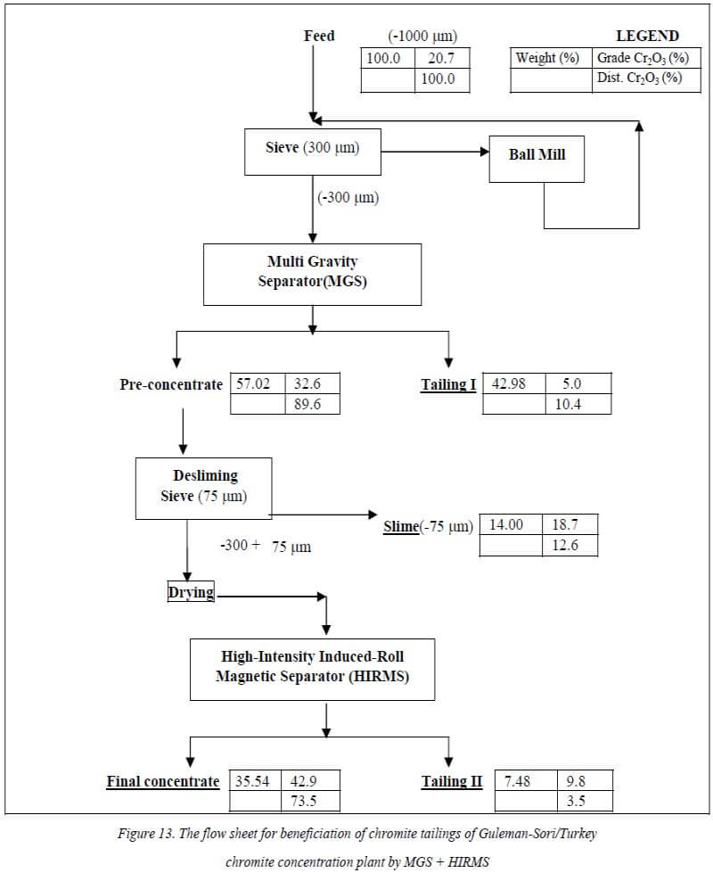
The flow sheet for beneficiation of chromite tailings from the Guleman-Sori/Turkey chromite concentration plant by MGS + HIRMS is given in Figure 13. With the optimum operation parameters of MGS and HIRMS combined, results are presented Table 6.
Conclusions
To produce a pre-concentration of chromite tailings, the optimum operation parameters of MGS are as follows: drum speed of 200 rpm, wash water 4 l/min, inclination of 5°, shake amplitude of 15 mm, and shake frequency of 4 cps. At these operation conditions, a pre-chromite concentrate containing 32.6% Cr2O3 with 89.6% recovery could be produced.
The optimum operating parameters of the HIRMS determined to produce final chromite concentrate from pre-concentrate are as follows: magnetic field intensity of 0.8 T, roll speed of 50 rpm, and feed rate of 250 g/min. At optimum conditions of the HIRMS, a final chromite concentrate containing 42.9% Cr2O3 with 85.1% recovery could be produced.
As a result of two-stage consecutive concentration (MGS+HIRMS), a saleable chromite concentrate that generally contains above 42% Cr2O3 could be produced.
The results of beneficiation studies showed that MGS+HIRMS might upgrade this kind of tailing materials without further grinding. In this way, it is possible to reduce the amount of waste material by recovering its valuable content.
http://citeseerx.ist.psu.edu/viewdoc/download?doi=10.1.1.519.2328&rep=rep1&type=pdf