
General Description.—A grapple dredge is, in principle, a derrick mounted on a float and swinging a grab bucket. Any derrick lighter may perform the operation of dredging by simply attaching a grab bucket to its fall. This, however, is merely a makeshift, and by no means constitutes a dredge. The operation of the bucket is but one of three principal functions of the grapple necessary to the complete business of “mud-digging.” They are:
- To operate the bucket
- To control the position and local movement of the dredge itself
- To handle the scows
The first requires a derrick, comprising boom, “A” frame and back legs and the requisite hoisting machinery, consisting of a double cylinder, double drum engine with boiler, auxiliaries and appurtenances. The bucket is a very important machine in itself, and its proper design is most essential to the efficiency of the dredge. It will be discussed in detail subsequently. It is hung from the end of the boom by two wires or chains by means of which it is raised, lowered, opened and closed and by which also the boom is swung.
The position and local movement of the dredge is controlled by spuds, by anchors, or a combination of both. Spuds are long timbers of heavy section suspended from tall masts or so-called gallows-frames and running vertically through openings in or pockets attached to the hull. They are raised by hoisting engines and, when released, penetrate into the river bottom by virtue of their own weight, thus anchoring the hull and holding it in position while digging.
The third function, that of handling the scows, is accomplished by three wires attached to the scows and lead to capstans or to hoisting engines on the deck of the dredge. The scow is thus moored to the starboard quarter of the dredge and, as each pocket is loaded, is hauled aft until the next pocket comes under the bucket.
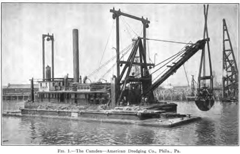
Figure 1 is a first-class representative grapple, the Dredge “ Camden,” a 7½ yard clam-shell, of the American Dredging Company of Philadelphia, shown working for the American International Shipbuilding Corporation in the construction of the Hog Island Shipyard on the Delaware River.
For convenience, in a more detailed exposition of the grapple dredge, each component part will be discussed successively as follows:
- The Bucket
- Boom, “A” frame and Back Legs
- Spuds, Spud-wells and Gallows-frame
- The Machinery
- The House
- The Hull
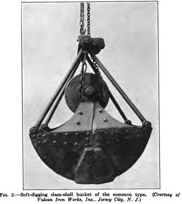
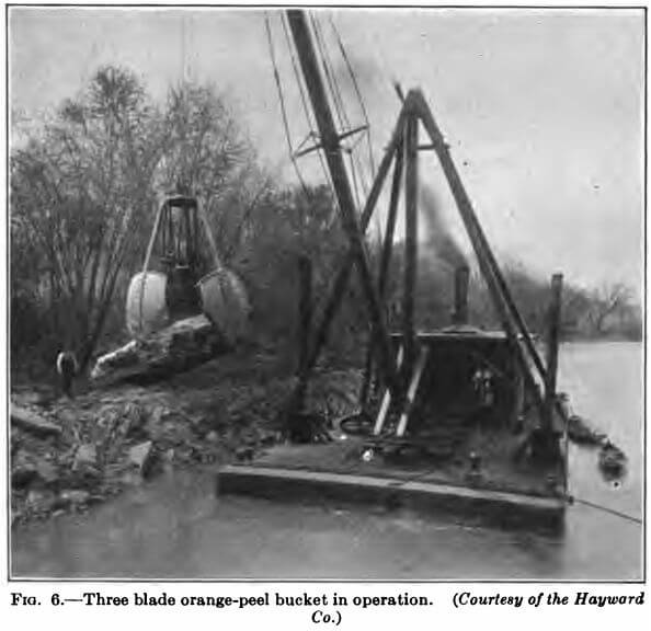
The Bucket.—The grapple dredge bucket, or the grab bucket as it is called, is of two kinds, the clam-shell and the orange-peel, as briefly defined in the foregoing classification. Both have the same principle of operation, but differ in that the clam-shell has two jaws or shells while the orange-peel has three or four. There are two principal types of clam-shell bucket, the common type and the sliding cross-head bucket, each of which may be distinguished further as a hard, medium or soft-digging bucket according to the class of material for which it is designed. Figure 2 is a soft-digging clam-shell of the common type.
A hard-digging clam-shell bucket of the sliding cross-head type with a capacity of 7½ cubic yards, is shown in Fig. 1 and the frontispiece.
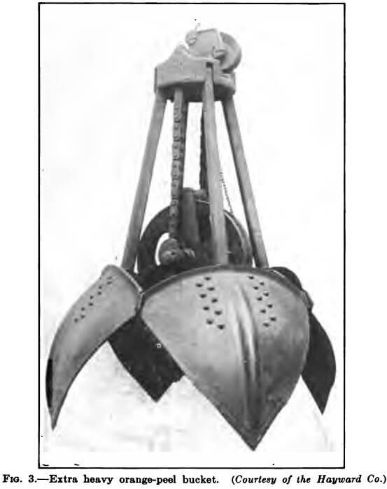
Figure 3 is the extra heavy, standard orange-peel bucket of the Hayward Co.
The Common Grab.—A general knowledge of the construction and operation of grapple buckets may be had by an analysis of the common grab.
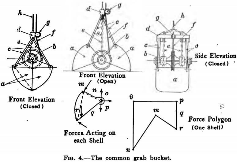
The bucket has five main constituent parts as shown in the outline drawing, Figure 4.
- The two shells a
- The spool and shaft b
- The four arms c
- The cross-head d
- The two closing chains e
The shells rotate about the main shaft, to which the spool is keyed. The spool consists of a large central sheave to the perimeter of which the closing wire f is attached, and two cylinders of smaller diameter, (the spools proper) to which the two closing chains e are fastened.
Whether a single casting or independent parts, these three wheels are keyed to the main shaft. The arms are pin connected to both cross-head and shells. The upper ends of the closing chains e are attached to the under side of the
cross-head d. The closing wire f is confined by a lead sheave g mounted on the side of the cross-head. The opening wire h is bridled to the cross-head.
Obviously, therefore, if the bucket is suspended from the opening wire with the closing wire slack, the spool and shells fall by virtue of their weight until the spool has rotated to the point at which the closing chains are vertical and taut, preventing further motion. The bucket is hanging open. If, now, the closing wire is given the load, and the opening wire slacked, the central sheave is caused to rotate so that the spools proper are rolled up on the closing chains toward the cross-head until the bucket’s jaws come together. The bucket is closed. The limit of tension in either opening or closing wire is the weight of the loaded bucket in air, plus an allowance for impact and
breaking bottom suction. With the bucket resting open upon the bottom, however, the closing wire tension at the beginning of the “bite” is necessarily less than the weight of the submerged bucket empty since the bucket obviously would be raised clear of the mud by a pull greater than its weight. As the bucket closes, the weight of the enclosed material becomes effective and the wire tension increases. The total stress in the two closing chains is equal to the product of the closing wire tension by the ratio of the diameter of the central sheave to that of the chain spools. The total compression in the four arms is equal to the sum of the total closing chain tension and the weight of the cross head divided by the cosine of the angle θ between the arms and chains.
Isolating one shell of the bucket, (Figure 4) the forces acting upon it when closing are the following:
mn—the thrust of the two arms.
no—one-half the upward pull of the main shaft,
op—the horizontal pull of the opposite shell.
pq—one-half the weight of shaft and spool.
qr—the weight of the shell itself.
rm—the resistance offered by the bottom material to the cutting lips of the bucket.
Beginning at m and going clockwise, the force polygon is as shown, mnopqr. The force no represents one half the sum of the closing wire and closing chain tensions. The force qr acts through the center of gravity of the shell. For any given position of the bucket, the force rm, or the cutting resistance at the lips, will be maximum when the tension in the closing wire is greatest (i.e., when equal to the weight of the submerged bucket) but when this condition obtains, the bucket is on the verge of rising so that the vertical component of rm is zero, or, in other words, the cutting force rm at the lips becomes horizontal, and its value may be determined for any position of the bucket by taking moments about the main shaft as a center, after computing mn as above and approximating the weight qr and its point of application. The form of the shell, therefore, in so far as it influences the magnitude of the moments mn, qr and rm about the shaft, is an important factor, i.e., the shape of the inscribed triangle formed by lines joining the main shaft, arm-pin and edge of lip determines the relation between the lengths of the lever arms of the forces acting.
From the above considerations, the following conclusions may be drawn in reference to the bucket’s ability to dig, or, in other words, its closing power as measured by the cutting force at the lips:
- It is a function of three co-related quantities: the weight of the bucket, the form of the shell and the ratio of diameters of central sheave and chain spools.
- It varies inversely with the depth of bucket from shaft to lip.
- It varies directly with the width and weight of the bucket and with the diameter ratio of sheave to spools.
- Weight in or near the curved back of the shells is no more effective than that concentrated about the shaft.
Bucket Axioms.—The bucket designed for soft-digging need not have inordinate closing power. It is made, therefore, as light as consistent with strength and durability and, in shaping the shells, the consideration of maximum capacity outweighs that of the adjustment of the inscribed triangle to maximum closing moment. The ratio of the diameter of the closing wire sheave to that of the closing chain spools is less than in the hard-digging bucket.
The hard-digging bucket requires great weight that it may obtain a full load in refractory material and, since the maximum combined weight of bucket and contents is fixed by the power of the main engine, bucket capacity must be sacrificed to bucket weight. A dredge capable of swinging a 10 yard soft-digging bucket will carry a somewhat smaller hard-digging bucket, probably about 7½ yards. The relatively large sheave to spool ratio, essential to the hard-digging bucket, results in a central sheave of considerable diameter, since the diameter of the closing chain spools cannot be less than enough to reel up with one revolution a sufficient length of chain to close the bucket. The designer should be mindful, however, that the perimeter of the sheaves must not extend below the horizontal plane through the lips of the open bucket, for the reason that, on a hard level bottom, the bucket so built instead of resting on its two lips in the wide open condition, would be supported by one lip and the central sheave and would have to close partially before being able to “bite.” This fault is negatived in the soft-digging bucket by the non- resistance of the bottom. It is entirely possible, too, that the closing power be excessive in proportion to the weight, causing the bucket to close too quickly before attaining the penetration necessary to get a full load.
The depth of any bucket from main shaft to lips must not be so great with respect to the width that, when closed, the main shaft is so far above the horizontal plane through the arm-pins that the closing moment is materially reduced for the last part of the closing. A bucket having this fault may be difficult to keep closed when loaded and will open very quickly.
The curvature of the shells in front elevation should be sharper than a full quadrant so that the bucket will not fit the “bite” so neatly as to create a mud suction resisting the lifting of the bucket.
In side elevation, the lips of soft-digging buckets may be straight or nearly so without detriment, but in the hard-digging type, lips of considerable curvature are more effective.
All buckets should be so designed in regard to shell curvature and maximum spread of opening that, when wide open, all parts of the shells may lie within the verticals through the lips. Otherwise, the pressure of the water upon the protruding shell surface has a tendency partly to close the bucket.
The Sliding Cross-Head Bucket.—It is difficult to design a hard-digging bucket of the common type just described that will combine all the advantages and omit all the faults mentioned. Better results can be obtained in tough bottom by the use of what is known as the sliding cross-head type, Figure 1, page 5. It consists, in principle, of a common grab bucket supplemented by a rectangular frame, the two side members of which act as guides for the travel of the cross-head and the lower member of which is formed by the main shaft of the bucket. The shells, instead of hinging directly on the main shaft, are pin- connected to the lower corners of a pair of triangular links, which, in turn, are hung from the main shaft. Thus the hinge centers of the shells are below the main shaft, with a consequent decrease in the length of the lever arm of the force rm, Figure 4, resisting the closing of the bucket. All the desirable features of an efficient bucket may readily be embodied without the presence of any of the faults. In addition to the prime advantage of great closing power, this bucket has the further good points that the elevation of the spool above the shell hinges allows plenty of open spread, keeps the spool clear of the contents of the loaded bucket and raises the central sheave well above the plane of the lips when open; while the frame adds effective weight, stiffens the entire structure and provides convenient fastening for the bucket poles. On the whole the sliding cross-head bucket is an excellent, durable and efficient tool.
For soft digging, however, the author prefers the common grab type, as, in this case, greater closing power is not required nor are bucket poles, and the frame, by adding unnecessary weight, reduces the capacity of the bucket.
Other Types.—In addition to the above, there are many types of grab buckets, some differing in minor detail and several in closing principle.
Many small buckets, i.e., from about ¾ to 1½ yards capacity are rigged to close by a three and four sheave block purchase through which the closing wire is reaved. This type is seldom used in dredging however.
Buckets of larger size have been constructed with the arms pinned to lugs projecting from the back or convex side of the shells, outside the bucket, in order to yield greater closing moment by increasing the lever arm length of the arm thrust.
The Stockton bucket resembles, in principle, a huge pair of tongs, to the ends of the long curved handles of which, the bridled closing wire is attached.
The Arnold bucket is closed by compressed air, which drives a piston in a cylinder contained in the bucket. The object is to correct the omnipresent fault of the common grab consisting of the loss in effective closing weight due to the lifting propensities of the closing wire.
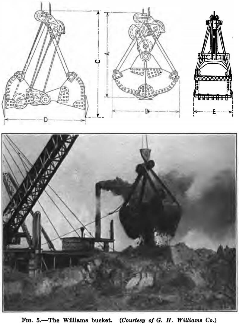
The Williams bucket, page 14, is a powerful, capable tool, unique in its closing power arm.
There are several single-wire buckets on the market,
but they are seldom used in dredging. They present the advantage of ready attachment to any two-drum hoist.
Grab Bucket Details and Appurtenances.—Both the cross-head and the shells may be either monolithic steel castings or built up. If castings, the shells, after wearing away at the cutting edge, may be fitted with attachable lips. The built up shell is made of steel plates varying in
thickness from about 3/8 to 5/8 inches according to the size of the bucket. They are reinforced at the corners and edges with bent plates and steel castings and usually at one or two intermediate points in the width of the curved face with plates and angles. The cutting edge or lip of each shell is generally strengthened by the addition of a steel casting or, preferably, manganese steel, the better to resist the severe abrasion. The arms, in section are variously round, square, rectangular and “H” shaped. All parts of a bucket, more particularly the pins, shafts and pin and shaft bearings should be generously proportioned and provided with renewable bushings.
The capacity of a bucket may be increased temporarily for soft digging, i.e., in material that has sufficient body and cohesion to stand up, by the use of so-called “side-boards” which are bent plates bolted to the arms, one to each shell, and having the effect of raising the backs and sides of the shells.
The tendency of the bucket to rotation must be prevented, as otherwise the two bucket wires would become crossed and fouled. This is accomplished in one of two ways. A wire called a “dorsey wire” is attached to the side of one of the bucket shells and is lead by sheaves up through the boom, about midway of its length, to a small pendant weight, rising and falling in the plane of the gallows frame. Or a pair of hardwood poles may be fastened to or set in the uprights of the bucket frame, extending up through rings attached to the boom head. The poles have the additional function of maintaining the bucket in an upright position on the bottom, i.e., preventing it from “falling over” when landed upon sloping, hard material. For this reason, they are considered by many “mud-diggers” to be an absolute necessity for efficient dredging in hard stuff.
Teeth are rarely used on large buckets, but on the smaller types, which are relatively light in weight, they are often helpful.
Boom, “A” Frame and Back Guys.—The derrick or crane element of the dredge, by which the bucket is handled, comprises boom, “A” frame and back legs with guys. The “A” Frame is usually vertical, or nearly so, and is set some distance back from the bow of the hull in order better to trim the ship and to permit a sufficient length of hull forward of the boom heel for holding the scow alongside when the first pocket is being loaded. Back guys and usually also back legs, i.e., struts paralleling and supporting the tension rods, extend from the peak of the “A” frame down to the after deck. There are generally two such. The boom heel is approximately in the plane of the “A” frame and its upper end is suspended from the peak of the “A” frame by a topping fall of fixed length so that the boom
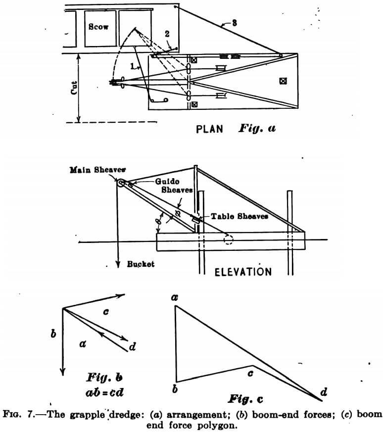
has a constant angle of inclination, which, for loading scows will be from 35 to 45 degrees with the horizontal, and generally less than 35 degrees for long-boom, banking machines. The two bucket wires pass over main and guide sheaves at the boom end, thence between the so-called “Table sheaves” mounted on the “table” which is analagous to the horizontal bar of the letter “A” in the “A” frame, and from there to the drums of the main engine. The two sets of table sheaves are spread some distance apart athwartships for the purpose of giving the bucket wires enough lead to the boom to swing it.
The weight of the loaded bucket and the boom and the pull of the engine create stresses in the boom, topping fall, “A” frame and back guys, which are readily determined. The manner of rigging and the forces acting at the boom end are shown in Figure 7a and b, and the stress diagram in Figure 7c. For the analysis, it will be assumed that the closing wire lies in the same vertical plane with the boom and that it takes the entire load of bucket and contents. Since this wire passes over a sheave in the boom head, the forces ab and cd representing the tension in it must be equal to each other and to the weight in air of the loaded bucket. It is advisable to increase all stresses by an impact allowance of at least 50 per cent. The boom compression ad and the topping fall tension bc may be scaled from the diagram, a study of which will reveal that both these stresses increase with the decrease in the boom angle θ and also with the decrease in the angle ∅ between boom and closing wire to engine.
To the above stresses must be added those due to the weight of the boom, which may be found graphically by drawing a second force polygon of the three forces, end reaction of weight of boom, boom compression and topping fall tension, omitting the bucket and closing wire.
The topping fall tension creates stresses in the legs of the “A” frame, alternately tension and compression as the boom swings and maximum when the boom is at the limit of its arc. The tension in a back leg will be greatest when the boom is in the plane of that leg. A graphical analysis will easily yield these stresses.
The boom is designed for combined compression and bending due to its own weight. The choice of section is influenced by the use of wire cable or chain for the bucket operation. Either may be employed with equal success, the preference being largely personal. If wire is used, the sheaves in the boom and on the table must be of large diameter in order to prevent undue bending stresses in the cable. The end of the boom, therefore, must be designed in such a manner as to provide a fork between the prongs of which, the two large sheaves are mounted on a shaft. The guide sheaves need not be so large. If chain is selected, all sheaves can be much smaller and those at the boom head may be suspended beneath the boom. There are many types of boom. In the smaller machines, it may consist simply of a single stick of timber with or without truss rods. In the larger dredges it may be built up of two timbers braced together side by side with sufficient clearance between to contain the two end sheaves. The timbers are often reinforced with steel plates or channels. Or it may be a lattice or truss boom of timber or of steel. A convenient form of the latter comprises four angles laced both ways and with deep plates at the ends and one intermediate point at least. Booms of this type require transverse or sway frames to resist racking strains.
The “A” frame members, if built of wood, must be supplemented with steel stay rods because of the reversal of stress. Although the back legs are subject to compression only in rare instances, yet it is advisable to combine in them both strut and rod the better to hold the “A” frame rigidly and truly in its intended plane without oscillation or vibration.
All sheaves, shafts, boxes and the derrick fittings should be proportioned generously to withstand the exceptionally severe wear and tear and to cut repairs and renewals to a minimum. The connections of the “A” frame and the back legs to the hull and the bearing and thrust of the boom heel casting upon the hull require care as to the proper transmission of the stresses to the hull and will influence the hull design to the extent of the provision of adequate strength at those points.
Spuds, Spud Wells and Gallows-Frame.—The grapple dredge is held in position, oriented and advanced in cut by means of spuds alone, or by wires alone, or by a combination of spuds and wires. Many machines are fully equipped both with a full complement of spuds and spud handling apparatus and with all the necessary machinery and appliances for operation by wires and anchors. This dual arrangement is obviously advantageous, since, while the spud method is more convenient through the saving of lost time in running lines and anchors and through the
non-interference with traffic and adjacent structures, yet there are times when the wires must be used, as in deep water or in swift currents or in the event of the breaking of a spud.
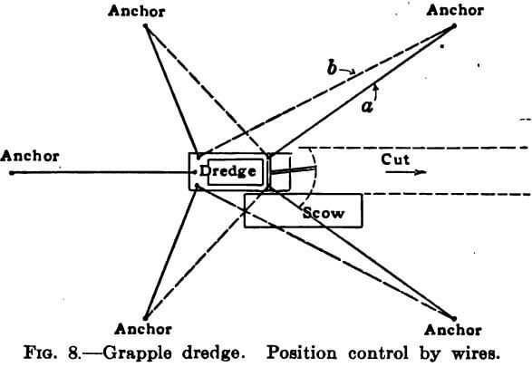
For position control by wires, five lines are generally used, two quarter lines on each side and a stern wire. They may be arranged as in Fig. 8a, or as in Fig. 8b. The rigging of 8b presents advantages over the former in that the two quarter lines forward are not as likely to foul the bucket in digging and dumping into the scow. In either case, the two wires on the scow side of the dredge, usually the starboard, must be elevated to clear the fight scow. This is done by leading them from the drums up through overhead sheaves, one attached to the end of a cross arm set in the “A” frame or gallows-frame for the bow wire and another mounted on a post or column erected on the after deck for the stern quarter line. Some machines have symmetrical wire equipment so that the wires may be elevated on either or both sides. Others have but two spuds, used in connection with the wires. It is readily seen that the high wires on one side and the low deck wires on the other exert a force couple tending to resist the listing of the dredge in the direction of the low wires when the boom is swung to that side.
Another expedient, which has been successfully used, to prevent scow and other interference with the anchor wires is the complete submergence of the wires by running them through sheaves in the toes of the spuds. This arrangement has been patented by the Osgood Dredge Company. The 10 yard clam-shell dredge “Finn Mac Cool” was so equipped.
The spuds in the smaller dredges are single sticks of round or square timber. In the larger machines they are square built-up members comprising four or nine pieces of heavy square timber bolted together. Some spuds are as large as four feet square. They are equipped with pointed metal shoes to facilitate penetration into the bottom and to add enough weight to overcome the buoyancy of the timber. All-steel and wrought iron spuds are sometimes used, both round and square.
The spud wells or openings at the deck through which the spuds travel may be either holes in the hull or housings attached to the sides and stern of the hull and called “outside” wells. The spuds must have sufficient clearance in the wells to permit perfect freedom of operation.
Three spuds are required for control entirely independent of wires, two forward at the sides and one aft, in the center. The two forward spuds are suspended from a tall, vertical rectangular frame called the “gallows-frame” approximately in the plane of the “A” frame and often braced to it. The stern spud is hung from a frame of more humble proportions or from a single mast maintained plumb by guys. The gallows-frame consists simply of two or four columns with a top cross cap and the necessary transverse struts and diagonal braces or knees. It must be borne in mind that the load upon the gallows-frame may be much more than that due to the dead weight of the spud because of the difficulty frequently encountered in pulling the spud out of the tenacious river bottom, i. e., “breaking the suction. ” It even may be greater than that developed by the maximum pull of which the spud hoisting engine is capable due to the fact that the careening of the dredge when digging is resisted by the reaction of the spud on the high side, comprising both weight of spud and the grip of the mud. The spuds are raised by the spud engine, having a wire leading through a sheave at the gallows-frame cap thence down to a collar encircling the spud and free thereof, but which grips the spud when the wire is taut. In rarer instances, the spud wire is made fast to the spud well housing from which it is lead down through a sheave in the toe of the spud itself, thence up through the gallows frame sheave and finally to the drum of the engine. Rigged so, the gallows frame need not be as high as the full length of the spud.
It is interesting to note here that in the case of a dredge swinging a long boom, excessive listing is sometimes prevented by the use of boom logs attached to the sides of the hull by chains of such length that the logs are afloat when the machine is on an even keel, but are raised clear of the water when the boom swings to the opposite side.
The Machinery.—The usual machinery of the clam shell dredge comprises the following units:—
- The Boiler: The Scotch Marine is a general favorite although Locomotive, Leg, Vertical and others are used. It is usually designed to carry from 125 to 150 pounds pressure, and is located aft, where, with the appurtenant coal bunkers and water tanks it acts as a counterweight to the active loads forward.
- The main engine for operating the bucket wires: generally a two cylinder horizontal type driving two drums through pinions, spur gears and frictions. The drums are in line athwartship and spread to give a direct lead to the table sheaves. The frictions may be either of the block or disc type, the latter being preferable for large machines. The pinions are as a rule below the elevation of the drum shaft. In the older dredges, the drums were thrown into clutch with the frictions by means of a long hand-operated lever in the pilot house. Now, however, steam or compressed air is used, except in small machines. The frictions are a very important item of the unit and should be given careful consideration. For efficient digging their grip must be positive and their release quick and complete.
- The Secondary Engines: The operation of the spud hoists, the anchor wire drums and the capstans or drums (as the case may be) for scow lines may be accomplished through two engines if desired, one forward and one aft. If the dredge be fully equipped with a complete complement of spuds and anchor wires and with symmetrical scow-handling equipment for right and left hand digging, a total of 14 drums or drums and capstans are required, 3 for the spuds, 5 for the anchor lines, and 3 on each side for scow control. The secondary engines should be double cylinder.
- Pumps: A minimum of two pumps is essential, one for the boiler feed and the other for pumping from the bilge, water tank or water scow and for fire purposes. If a surface condenser be used, circulating and air pumps will be required.
- Condenser: The main and secondary engines may be run as condensing engines by piping the exhaust steam from all to a single condenser.
- Miscellaneous equipment, such as electric light plant, air compressor and refrigeration plant.
The runner’s control in the pilot house comprises simply main engine throttle and frictions. The secondary engines are under local control upon signal from the pilot house.
An idea of the relative engine sizes may be had from the following data: The dredge “ADMIRAL,” shown on the frontispiece, has a hull 110 ft. x 39 ft. x 11 ft. 10 in., swings a 7½ yd- bucket and has a horizontal, two-cylinder main engine 20 in. x 24 in. The dredge “BALTIC,” American Dredging Company, has a hull 110 ft. x 39 ft. x 12 ft., a 5½ yd. bucket and a horizontal two-cylinder main engine 16 in. x 24 in. The dredge “COLUMBIA,” of the same Company, has a hull 90 ft. x 35 ft. x 10 ft., a 4 yd. bucket and a two-cylinder horizontal engine 14 in. x 20 in. The “PACIFIC” (same owners); hull 78 ft. x 23 ft. 9 in. x 7 ft., bucket 2¼ yd., main engine, two-cylinder, horizontal 10 in. x 15 in. The dredge “FINN MAC COOL;” hull 120 ft. x 40 ft. x 12 ft. 6 in., bucket 10 yd. (soft digging) main engine, two-cylinder, 18 in. x 24 in. The “ADMIRAL” mentioned above will swing a 10 yd. soft-digging bucket. Dredges of this size usually have secondary engines of from 8 x 10 to 10 x 12 double cylinder. The engines of clam shell machines are seldom run condensing.
The House.—The usual grapple boasts a two-story frame or steel house, the first floor of which comprises boiler and engine housing, galley and mess room; and the second floor, pilot house or operators room, and sleeping quarters for the crew and inspector. Deviations in detail from this arrangement are not uncommon. The main engine and boilers are generally depressed below the main deck.
The Hull.—The dredge hull must be of sufficient size to contain, with comfortable freeboard, all the above mentioned superstructures and machinery with adequate fuel and water storage. The beam and the length forward and aft of the “A” frame must be sufficient to provide adequate stability when dredging, i.e., to keep the ship in reasonable trim in resistance to the listing moments of the swinging boom and bucket. The width of hull cannot be so great, on the other hand, as to necessitate an excessive length of boom in order to reach beyond and clear the pocket coaming of the light scow. The freeboard should be such as to assure some reserve buoyancy when the machine is at the point of maximum inclination due to the limiting position of the loaded bucket in its arc. In brief, the problem is the proper co-ordination of hull dimensions with the location and height of “A” frame, length of boom, bucket capacity and disposition of machinery, fuel and water tanks. The solution is simplified by the commonly rectangular shape of the hull both in plan and section, with rake at the stern only to facilitate towing. Moulded hulls have been constructed for grapples but are quite rare. The total depth of hull is the sum of the draught of the empty hull, the displacement depth due to machinery, superstructures, fuel and water, and the desired freeboard. The first quantity is first approximated by roughly estimating the total feet board measure of lumber in the hull (or the tonnage, if steel) and checked subsequently from the accurate bill of material taken from the detailed design. The ratio of hull depth to the width is as a rule slightly less than 1 to 3 and that of beam to length a little more than 1 to 3.
The principal loads acting upon a dredge hull are the normal water pressure on bottom sides and ends; the weight of the machinery, more or less concentrated under the main engine and boilers; the pull of the main and secondary engines; the weight of fuel, water tanks and super-structure; the thrust of the heel of the boom which may be in any vertical plane passing radially through the heel casting; the alternate thrust and pull of the A frame; the pull of the back guys; the bearing of the gallows-frames; horizontal force couples due to spuds in their wells or to anchor wires; and finally wave action, causing both local impact and bending moments in the structure as a whole. While the majority of the above loads are capable of reasonably accurate determination, it is hazardous to design upon a purely theoretical basis. The efficiency of a dredge depends among other things upon the ratio of its working time to the total. The more the time lost for repairs and renewals, the less valuable is the unit. Therefore, either temper the theory with the knowledge resulting from practical experience or else use a large safety factor, to the end that the members shall be proportioned generously to withstand the severe duty required of “mud-diggers.”
Most hulls are built of wood. They are virtually heavily constructed boxes stiffened with bulkheads, trusses and knees to resist distortion. A hull that has become convex upward longitudinally is said to be “hogged” and when concave upward, “dished.” Although varying widely in detail, the usual design is, in principle, as follows: The bottom planking is laid transversely upon the under side of longitudinal keelsons, heavy timbers spaced from about 2 ft. 6 in. to 4 ft. c.c., extending the full length of the ship and spliced with long scarf joints from 4 to 6 ft. in length. The reactions of the keelsons are taken by heavy cross keelsons, running athwartship at greater intervals on top of the keelsons and notched down and over them. Upon the cross keelsons in turn bear the longitudinal bulkheads or trusses and the stanchions. There are at least two trusses, usually of the Howe type, or solid bulkheads extending the full length of the hull which, with the keelsons and side planking (acting also as deep longitudinal girders) furnish the requisite stiffness fore and aft. Upon the trusses, bulkheads and stanchions are placed the deck beams carrying the deck planking. More commonly the deck beams are transverse members and the decking longitudinal. The deck is usually crowned about 3 inches. The side planks, called “strakes,” are spiked to the side stanchions, the thrust of which is transmitted to the cross keelsons and the deck beams by fore and aft ribbon pieces sometimes called side cleats. Frequently two or more side strakes are thicker than the others, extending beyond the side plane and acting as fenders. The inclined members of the stern are called rake timbers. All the exposed planking is dressed, outgaged and caulked with pitch and oakum. Deck spikes are covered with wood plugs. Transverse stiffness is provided by lateral bracing or by hackmatack knees.
Operation.—The dredge is towed to the site of the work and placed in position at the starting point of the project. Her spuds are dropped or lines and anchors set as the case may be. The cut to be dredged is indicated by range targets stationed ahead of the dredge. A light scow is brought alongside by the tug acting as tender and moored to the machine by the wires of the scow handling machinery, which are generally 3 in number located as follows: A breast wire leading from a “U” bolt in the pocket coaming of the scow to the port bow of the dredge; a second wire attached to the port stern corner of the scow and running forward to the starboard bow of the machine; and a third wire extending from the starboard stern of the scow to the starboard stern of the dredge. The arrangement is shown in Figure 7, page. 17. It is customary to interpose a boom log between dredge and scow.
The deck hands board the scow and, using bars as levers, wind up the door chains of each pocket about the shaft until the doors are raised to the closed position and held so by ratchet and pawl. The end pocket nearest the dredge having been thus closed, digging is started.
The operator in the pilot house releases the starboard friction to slack the closing wire and the bucket opens hanging by the port wire. He then slowly lowers the open bucket into the water by easing up the port friction until the bucket rests on the bottom, ready for the bite. He releases the port friction, grips with the starboard and partly opens the throttle. The closing wire is thus stressed and the bucket closes upon its load and rises. Keeping the load on the closing wire and controlling the resulting boom swing to starboard by a lesser backing strain on the port wire, the operator lifts the bucket up over the side of the scow and pocket coaming until it is suspended above the pocket, when he closes the throttle, holds fast the port wire and releases the starboard, opening the bucket. Still gripping with his port friction, he opens the throttle partially, swinging the boom to port and then lowers it open into the water as before to take another bite. When the pocket is fully loaded, he signals by blowing the whistle to the deck hands who haul the scow aft by operating the scow-line drums until the next pocket is in position for loading. The scow settles more and more deeply in the water as the loading progresses, constantly decreasing the necessary height of bucket lift.
If dredging in tide-water, the operator must know the stage of the tide so that he may dig the depth specified, referred to the datum, usually mean low water. A tide guage, therefore, is set where he can see and read it. In addition to actul lead-line soundings over the bow of the dredge, he is guided in his digging by his knowledge of the overall height of the bucket or by graduations, or a single mark upon one of the bucket wires or chains or upon the bucket poles, or by means of a wire leading from the bucket through sheaves in the boom end and “A” frame thence through reduction tackle to a weight sliding on a graduated scale in the pilot house.
When specified depth has been made over the area within reach of the bucket, the dredge is moved ahead or “advanced in the cut.” If the machine is operating under wire control, this movement is accomplished simply by winding in the forward quarter lines and slacking the stem quarters and stern line. If spuds alone are being used for position control, the advance is achieved by so-called “walking on the spuds,” as follows: The bucket is grounded, i.e., lowered into the mud and the stem and one bow spud are raised clear of the bottom. The operator then stresses that bucket wire which tends to swing the boom toward the side on which the bow spud is up, but the boom is anchored by the grounded bucket and the dredge is free to pivot about the third spud, so that the boom retains its position and the dredge swings. When the free bow corner has thus been pulled forward the desired distance, that spud is dropped and the operation repeated for the advance of the other bow spud, after which the stem spud is dropped and digging is resumed. When all pockets of the scow are full, the operator blows for the tug to bring a light scow and to remove the loaded one.