Table of Contents
Over the past several years, a number of deaths have occurred in the minerals industry as a result of workers entering bins or silos to correct flow stoppages or to conduct maintenance. In almost all of the fatalities, the direct cause of the accident could be attributed to a failure on the part of the victim to obey one or more of several common-sense safety regulations. As a result, there is a temptation to prescribe preventative action based solely on such conclusions; namely, better safety training and closer supervision.
But there may have been underlying causes for the accident, causes not necessarily evident to an inspector trained primarily on the safety aspects of the problem. Why did the victim have to enter the bin? Is this action a routine part of his job, or just an occasional happening? If routine, is there a design or process change or equipment that would minimize the problem? If it is a material flow stoppage, could it have been avoided by better bin design or the use of flow-aid accessories, or was it an unavoidable result of the property of the material being stored, possibly because of weather conditions?
These are questions that are more properly in the jurisdiction of engineering rather than safety, but unless the accident is also viewed in this manner the questions will never be asked.
This handbook attempts to treat the problem of preventing bin-related accidents first of all from the ENGINEERING aspect; that is, what can be done to prevent the problems that require a worker to enter a potentially hazardous bin situation; and then from the SAFETY stand-point, assuming that eventually such action will become necessary.
It discusses common material flow problems as a function of the “flowability” of the material being handled. Materials are divided into four general classifications based on their “flowability”, and suggested bin designs, including flow-aid accessories, are provided for each. A comprehensive table listing the flowability classification of many materals is included, as well as practical guidelines for estimating flowability if a material is not listed. Sources for more detailed design help are also provided.
Federal regulations concerning the safety of workers around bins are reviewed in the last chapter. Additional suggestions are made, based on our study of fatal bin-related accidents, to better educate the response of workers to material flow stoppages.
Bin Flow Theories
Materials flow from a bin in one of two ways: funnel flow or mass flow. Whether a material shows a funnel flow or a mass flow pattern from a bin is determined by the flowability of the material and bin design.
Most bins are of the funnel flow type. As material is drawn from the bin, a flow channel forms extending from the bottom opening to the top of the material (Figure 1). As the withdrawal continues, fresh material slides into the channel from the top. The bin level is lowered in this manner with the material surrounding the channel remaining stationary.
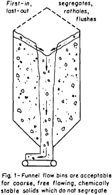
Funnel flow results in the first material being the last out. Therefore, if the material being stored has a tendency to cake or deteriorate with time or consolidate with pressure, ratholing occurs with resultant loss of flow.
Funnel flow bins also tend to segregate materials of nonuniform composition. All bins segregate materials at point of charging – the larger particles flowing to the side of the bin. With funnel flow, the fines will accumulate in the center of the bin; and thus fines will predominate in the discharge when the level in the bin is rising. Conversely, coarse materials will predominate when the bin level is falling.
The design of funnel flow bins is characterized by short, small-angled cones. Flow aids are generally needed to minimize material flow stoppages. The best application for funnel flow bins is for coarse, free flowing solids, with little tendency to bridge, but with the proper selection of flow aids (air gravity conveying and fluidization slides, air pads, vibrators, etc.) funnel flow bins can be made to handle materials of lower flowability with a minimum of problems.
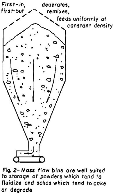
Mass flow bins are specially designed for specific products and are less common in industry. In a mass flow bin (Figure 2), all materials is in motion whenever any material is being drawn out. The material flows from the bottom and the material above moves down to replace it. With mass flow, the first material in is the first material out; and although material segregation occurs during charging, remixing occurs in the cone at a point of discharge.
Designing for mass flow without flow aids requires an extensive knowledge of the properties of the bulk solids to be handled; and although designing a bin for good mass flow is definitely possible, changes in material properties or lengthy work stoppages can result in flow problems. Flow aids, therefore, are also needed to at least initiate flow in these instances.
The design of flow bins is characterized by cones with steep tapered sides, and may require considerable head room. In addition, bins designed for gravity mass flow would have limited versatility for other materials. These points, coupled with the extensive study of material properties required for the design, undoubtedly lead some would-be purchasers to opt for funnel flow bin designs with flow aids.
Common Material Flow Problems and Solutions
That property of a bulk material that determines how well a material will flow from a bin has been given the term “flowability.” Made up of a number of definite properties, it is a measure of the freedom of the constituent particles to move when subjected to a force – in this case, gravity. Factors which affect this freedom of movement are size, size range (degree of fines present), shape, hardness, moisture content, etc.
The CEMA publication “Classification and Definition of Bulk Materials”, defines free-flowing bulk materials as ones in which the constituent particles have low strength, that is, have low resistance to movement relative to one another and maximum freedom to move individually when placed in motion. Materials of this type rarely cause bin flow problems. As this resistance to movement of the constituent particles increases, the bulk material flow becomes sluggish. In bins, the result may be that material flow ceases.
The loss of flow of a material from a bin under normal circumstances is generally due to the “arching” or “bridging” of the material. “Hang-ups”, or clinging material, is generally a less severe problem; and although it can result in loss of flow, in a continuously working system it is more generally considered loss of inventory volume. These problems are depicted in Figure 3.
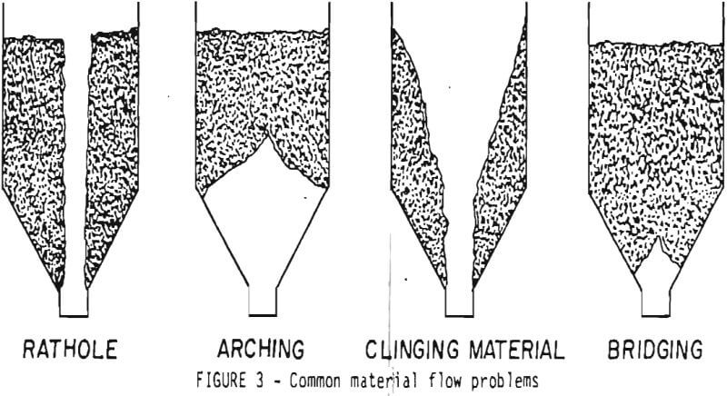
Bridging and arching are the same problem to differing degrees, and the terms will be used interchangeably throughout this handbook. They are the result of packing of the material due to the weight of overburden and its resistance to flow against itself and along the bin walls.
The strength of the bridge is essentially a function of the strength of the stored material and the bin design. Material properties and head of material determine. the strength of the stored material while bin design factors include hopper shape and slope, and size of the bin discharge opening. Some of the material properties of concern are bulk density, compressibility, and tendency to absorb moisture.
The bridging tendency can be minimized and the material kept flowing by weakening the bridge at point of contact with the cone. This can be done passively by the proper cone geometry or altering the cone surface, or actively by use of flow aids, such as air/gravity conveyors (aeration pads and slides) air cannons and mechanical devices. It is not necessary to affect the total cone surface, but only to weaken the bridge at several points, thus collapsing it.
Aeration pads affect only a limited area and thus to be effective, must be installed in the area of the bridge-cone contact. The same is true for air cannons to a lesser degree. Aeration slides and coatings such as slippery laminates and mechanical bridge breakers may be installed nearly the full height of the cone, and thus can affect bridging anywhere on the cone surface.
The strength of the bridge can also be affected by reducing the head of overburden. Active bin bottoms, or vibrating hoppers in effect do this by supporting the head load above a built-in baffle and, through vibration, metering the material into the cone below. Although more expensive than most flow aids, their versatility and reliability for maintaining flow for materials with a wide range of flowability appear to be gaining them increased popularity.
Classifications of Bulk Materials
CEMA recognizes four general classifications for bulk materials based on their flowability:
Class 1 – very free flowing,
Class 2 – free flowing,
Class 3 – average flowing,
Class 4 – sluggish.
These classification designations will be used for this handbook; and in terms of material flowability and bin design, they are intended to convey the following:
Class 1. Very Free Flowing – Material in this class will flow through almost any size opening with no additional help. It is very unlikely that any material covered here will fall in this class. It is concerned mostly with grains, plastics, etc.
Class 2. Free Flowing – With no adverse moisture or weather conditions, these materials flow about as well as Class 1 materials. Most of them may occasionally heed a flow aid accessory to get them started, but once started they flow with a minimum of help. Uniform, dry granular materials such as sand or fine coal are typical of this classification.
Class 3. Average Flowing – The majority of materials fall into this class. They require a constant flow aid (e.g., supply of air or vibration) to keep the material moving; however, there should be very few hang-ups if the system is designed properly. Dry, fine clays and hydrated lime would be typical of this classification.
Class 4. Sluggish – The bin system should be designed with utmost care for materials in this classification. Expert help should be obtained. Bin clean-out must be a part of scheduled maintenance; but with proper design, bin clean-outs and thus bin entries will be less frequent. Damp sand, soil and wet coal are typical materials that fit this classification.
As noted above, each material classification has different bin requirements to maintain flow. The obvious solution to the selection of the proper bin for a particular material then is to specify design criteria, including flow aids, for each of the flowability classifications and to show how the classification of a material can be determined. This can be done to a degree; but as expected, some flow aids are essentially equivalent, so far as getting the job done, but one may be more suited than another for a particular type of material. Thus, hard and fast criteria in terms of bin design and accessories cannot be specified. We will, however, review the various types of flow aids available and provide some guidelines as to their utility.
A similar degree of inexactness is inherent in the flowability classification of any given material. Generally, the classification that a material will belong to is a function of its size, size range (degree of fines present), shape, hardness, moisture content, etc. As a general rule, extremely fine powders (<200 mesh) deaerate and pack readily (dusts, talc, etc.), and dry, uniformly-sized larger materials will be free flowing. Air pads may be needed to move the first material and merely gravity or small vibrations can be sufficient for the second. However, added moisture or a higher portion of fines can change their flow properties to a lower classification.
Ideally, a bin system for a particular material should be designed for the worst category that the material could appear in, taking into account changes in moisture content, adverse weather during mining, processing, or hauling, and such factors as size and size range changes. This would minimize the possibility for flow stoppages and the need for entering the bin. Occasional hang-ups will still occur, however, and thus this handbook has devoted a section to safety in bin-entry problems.
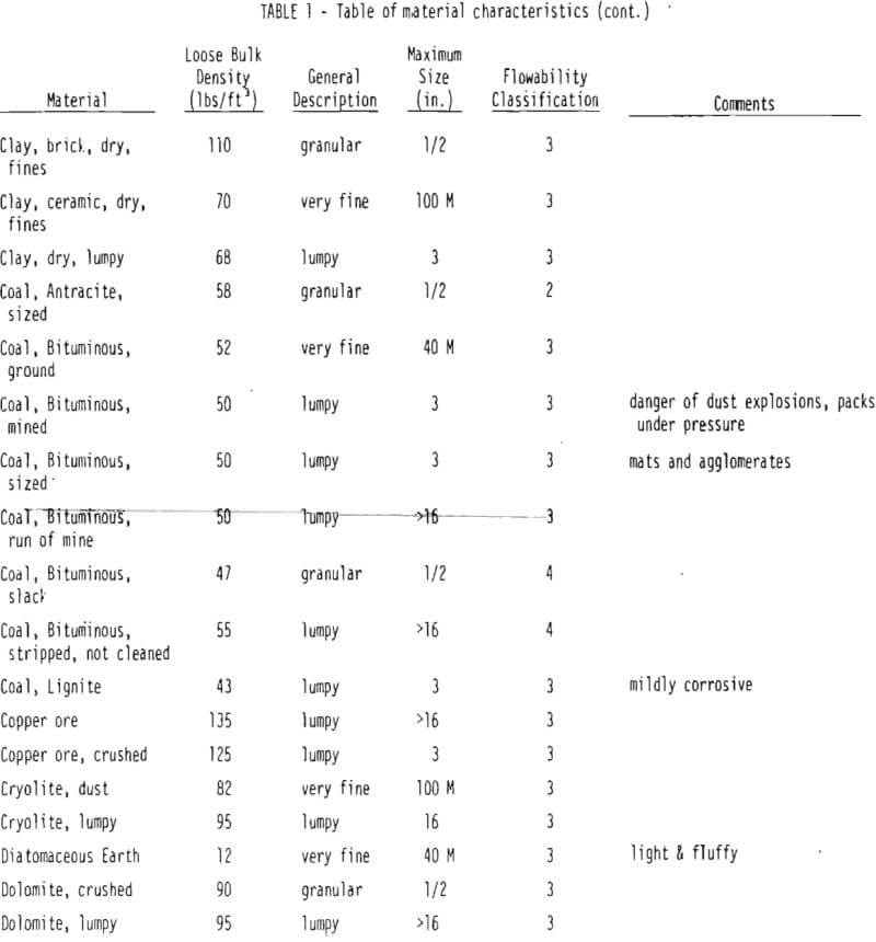
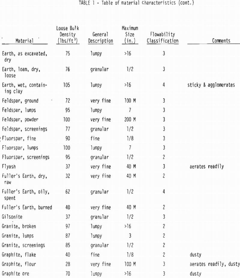
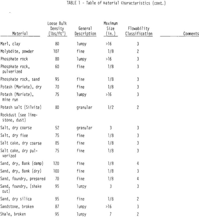
Table 1, excerpted from the CEMA publication referenced earlier, is a listing of properties and flowability of materials that might be considered for storage in small bins [throughout the minerals industry. Although it is a diverse listing and includes materials that are not minerals, it includes those minerals that make up over 90% by weight of all materials mined in the U.S. Besides the flowability classification, the table includes different sizes of the same material, general particle description, and bulk density, all of which would be of help to an engineer in matching his material to the table listing.

Classifying Your Own Material
If the flowability classification for the material to be stored is not found in Table 1, it should be determined, either by a testing firm or by tests of your own.
Simple tests for estimating the flowability of dry materials have been developed by Carr and, although the tests were developed for solids with relatively fine particles they fortunately can be applied to mixtures containing larger aggregates. In general, the flow of those bulk materials which contain a range of particle sizes, including both coarse and fine particles, is invariably governed by the flow properties of the fine fraction. The coarse material is a neutral ingredient so far as flow properties are concerned; and if screened out, that portion larger than 0.01 inches is invariably free flowing (Carr).
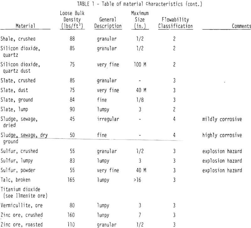
Carr measures four flow characteristics of the bulk material, assigns up to 25 points to each as a function of the test results, and uses the sum of these to determine the flowability of the material. The description of his flowability classifications as a function of the flowability point total is shown in Table 2. Beside it is the approximate assignment of flow classification taken from the CEMA bulletin based on the description of the material.
The evaluation of the flowability classification of a dry ma terial involves the determination of four properties: (1) angle of repose, (2) compressibility, (3) angle of spatula, and (4) either cohesion or coefficient of uniformity. The choice of tests for (4) depends on the apparent property of the material, but for minerals, the coefficient
of uniformity test is more applicable. Test procedures for the four properties are as follows:
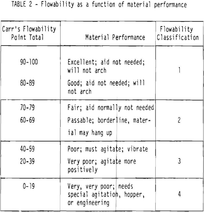
Angle of Repose
This is the angle with the horizontal that is made by the cone that is formed when a material is carefully dropped from a point source and allowed to pile up undisturbed until a constant angle is measured. The coarser the material, the larger the pile should be for the test. The more free flowing the material, the lower the angle; but care should be taken to make the determination on a sample representative of the material to be stored. Free flowing dry sand, for example, would have an angle of repose of 34°; whereas wet sand could approach 60°. If material conditions may vary, choose those that would provide the lower flowability (higher angle of repose).
Compressibility
The difference between the loose (L) and packed (P) bulk densities of a solid material, expressed as percent, is its percent compressibility. That is:
% compressibility = P – L/P x 100
Carr determines the densities on that fraction passing a coarse screen (about 10 mesh), first carefully screening the material into a measured volume to overflowing, leveling off, and weighing to determine the loose bulk density; and then while vibrating the same material over a five minute period, again refilling the container and determining the packed density.
The more compressible a material is, the less flowable it will be; and conversely, the less compressible, the more flowable. The borderline between free flowing and non-free-flowing is about 20 to 21%.
Angle of Spatula
This is a measure of the internal friction between material particles. A spatula with a 7/8 to 1 inch wide blade is inserted horizontally into a pile of the test sample and lifted out vertically.
The angle the material makes with the horizontal blade is measured at several places on the spatula and averaged. The spatula is then tapped gently, dislodging some of the material, and the angles measured again. The average of these two measurements is taken as the angle of spatula and used in the flow computation. A wider spatula should be used for materials that are nonuniform in either size or shape.
Except for very free flowing materials, the angle of spatula will always be higher than the angle of repose. And similar to the angle of repose, the lower the angle of spatula the more free flowing the material. An angle of 40° or less is considered free flowing.
Uniformity Coefficient
This is a measure of the size uniformity of a material and is the numerical value arrived at by dividing the width of the sieve opening (in inches) that will pass 60% of the sample by the width of sieve opening that will just pass 10%. The test is conducted by performing a sieve analysis on a known weight of sample using from 40 to 325 mesh.
A uniform material is generally free flowing and thus would give a small uniformity coefficient. Nonuniform materials are less free flowing and would give a large sieve variation and higher uniformity coefficient.
Calculating Flowability
The values obtained for the individual flow properties are used to determine the flowability point score for each, using the graphs in Figure 4. The total of these points art used in Table 2 to determine the flowability of the sample according to Carr’s criteria, and from that, our corresponding Flowability Classification.
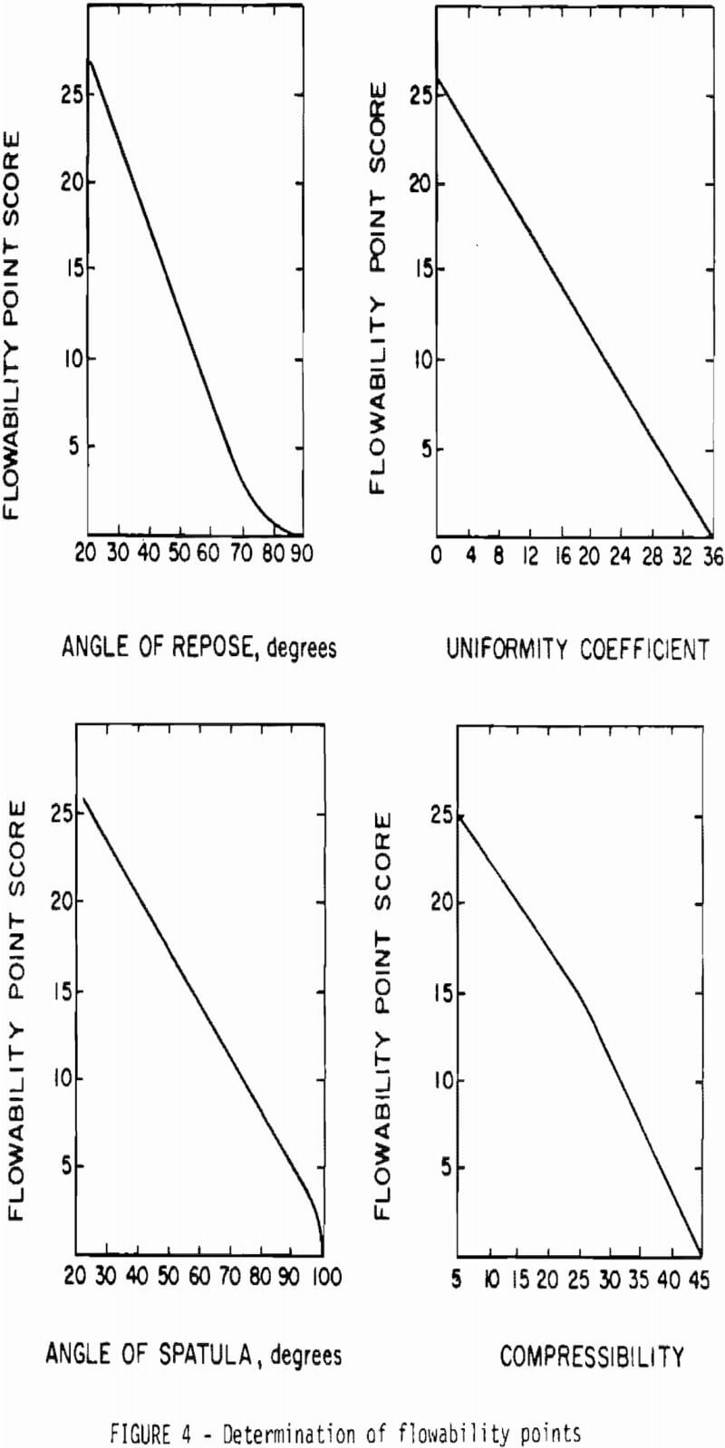
Table 3, for example, shows sample determinations for two materials.
A flowability point total of 96 for Material 1 places it in our Flowability Classification 1, and would require no flow aids. Material 2, on the other hand, shows a flowability point total of only 25.5, placing it in our Flowability Classification 3. This material has very poor fowability, will need positive agitation to move, and will require considerable thought on bin design and accessories.
Bin Flow Aids
A properly designed bin system can go a long way towards reducing the frequency of bin accidents by minimizing the necessity for a worker to enter a bin. Although bins can be designed to theoretically make most any material free-flowing, generally, a bin system will include one or more flow aids to induce or maintain material flow.
A variety of flow aids for installation on new or existing bins can be tailored to solve almost any bin flow problem. These can be grouped into the following types:
- Air/gravity conveying
- Vibration
- Sonic fluidization
- Live bin bottoms
- Liners
Air/Gravity Conveying
Proponents of air/gravity conveying, as a means of achieving a flowable material in a bin, generally consider that almost any material can be fluidized through aeration, where aeration is the driving of air into the void spaces between particles. This results in a material of lower bulk density, with reduced internal friction, that is incapable of generating the material strength to support bridging. It can be fluid-like in its flow properties.
Not all of the materials in the bin needs to be aerated, but just that material at those points where it has a tendency to bridge. This will be in the cone, generally near the discharge. In practice, a good many but not all materials can be fluidized, and some considerably easier than others. But where fluidization is readily achieved, the technique is simple and the equipment relatively inexpensive.
What Materials are Candidates? – Materials that aerate easily are generally fine (<60 mesh) powders, with flowability classifications 2 and 3. Mixed particle size materials do not aerate well, as the heavier particles tend to sink and segregate.
Equipment manufacturers generally will have a background of experience on materials that respond to aeration, or can conduct simple tests that will evaluate the possibility with questionable material. A point to consider, besides the physical property of the material to be stored, is to whether the aeration air, with the likely inclusion of moisture, might react with or cake the material after a period of time. This may result in hangups or loss of storage efficiency on the part of the bin.
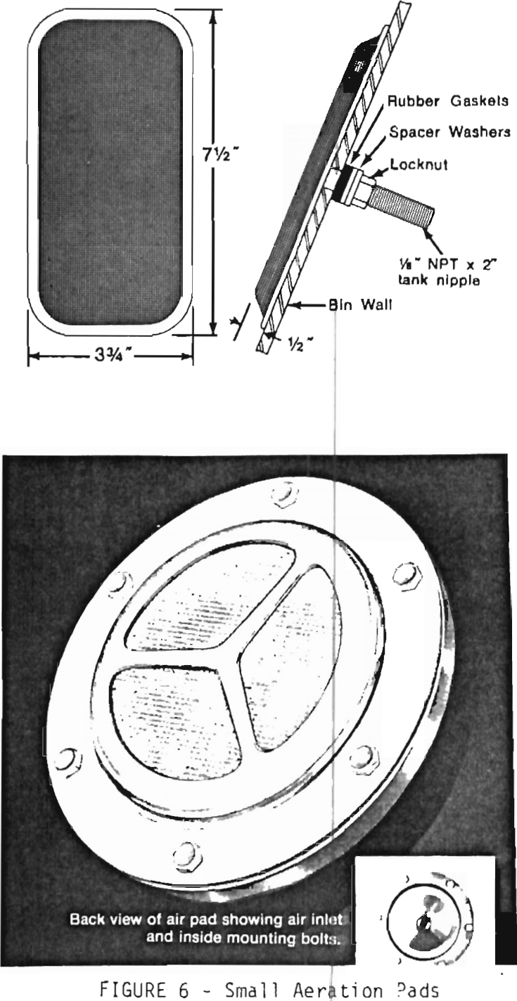
Aeration Equipment – To aerate, low pressure air is introduced into the cone area of the bin through one of a variety of devices. A common design consists of a chamber with a porous cloth, ceramic or metal surface as part of the bin inner wall; air is introduced into the chamber from the rear and travels through the media into the material (Figure 5). A high flow resistance in the media keeps the flow constant
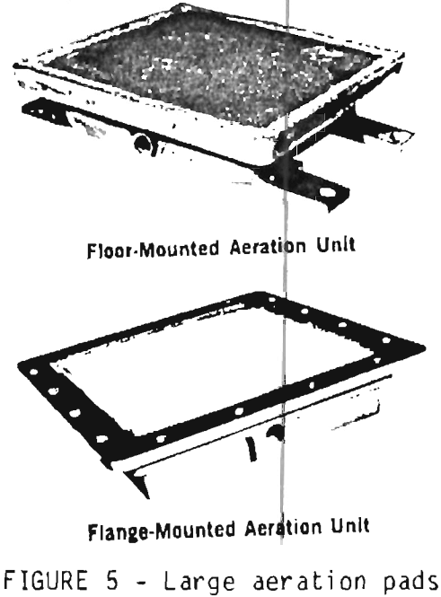
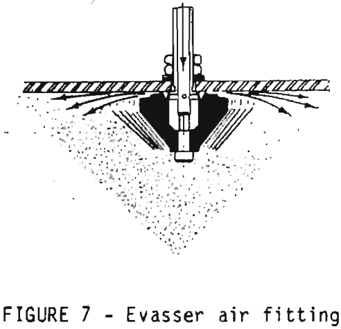
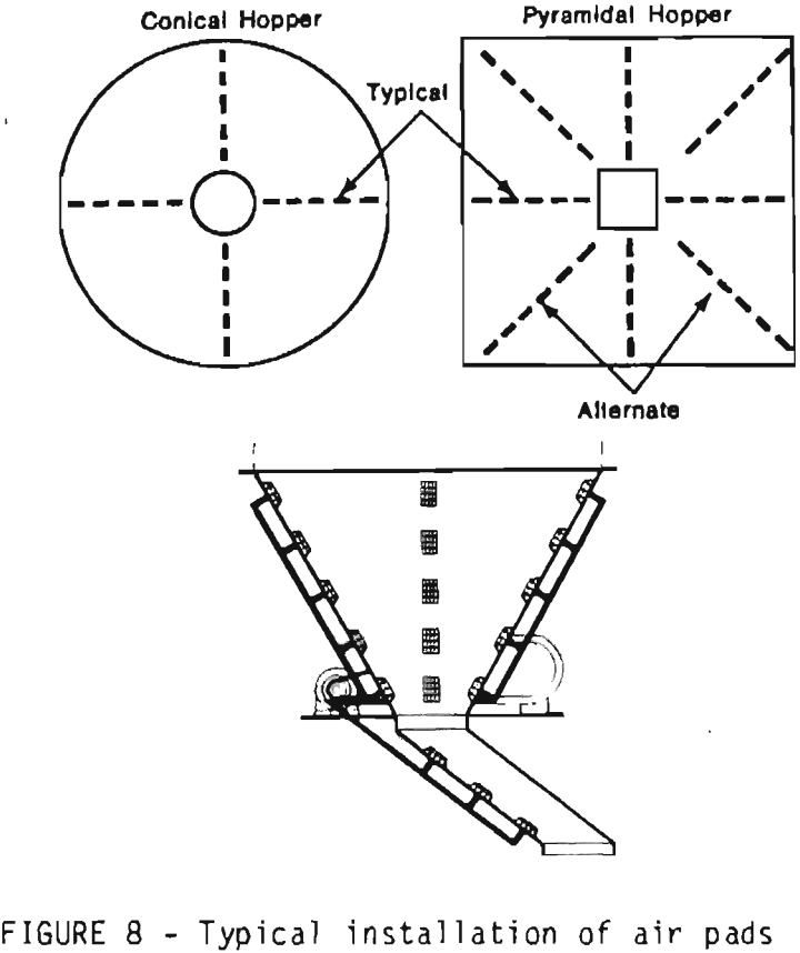
over the chamber regardless of the material depth. A series of many small pads may do as well as several large ones, with lower air consumption (Figure 6). An alternative design is a large circular pad installed in the bin bottom and slightly inclined toward the flow outlet. Several manufacturers make rubber fittings (evassers) that force air out radially from the fitting to affect a larger areas; these may require the use of compressed air (Figure 7).
To be effective, the aeration air must be introduced into the material at point of bridging. An aerating device cannot break an arch formed above it. Recommended installation by most manufacturers is along a line from the cone outlet, up the side of the cone in one or more places. Units are spaced on 12 to 24 inch centers. If the bin is square or rectangular, the air may be added in the corners of the hopper (Figure 8). Air may be supplied by plant air or a blower installation at about 2-5 psig. Consumption may vary between 10 and 50 SCFM per square foot of air pad surface. if the bin material is sensitive to air, other gases may be used, with corresponding supply and recovery systems. In any case, the aerating fluid should be free of condensed moisture that can clog the air pad and wet the material.
Advantages of aeration over other methods include:
- quiet operation,
- no operational damage potential to bin,
- no moving parts, resulting in low wear on aerater,
- reduced product damage,
- generally low-cost installation.
Disadvantages include:
- only works on fine (60 mesh or finer) aeratable material,
- requires an air supply,
- increased potential airborne dust problem,
Vibration
Vibrating a bin is one of the oldest forms of moving materials, and in its crudest form consists of a hammer and strong arm. Today many companies make accessory vibrators, so that one is available to solve almost any problem.
When properly installed and used, a vibrator breaks the friction between the material and the bin by flexing the bin sides. This in turn imparts movement into the material which disrupts particle-to-particle and particle-to-bin wall bonds, allowing the material to flow. Different materials may respond to different frequencies and different amplitudes; a variety of vibrators are available to meet these needs.
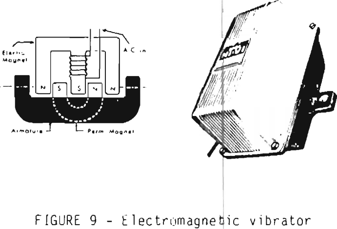
Vibrators are available in four general power classifications: electromagnetic, electric motor driven, pneumatic, and hydraulic. Electromagnetic vibrators consist of an electromagnet and a permanent magnet and work on AC current. Reversing of the electromagnet’s field moves the pivot mounted permanent magnet, producinq the vibration. These generally operate at low force, one frequency, don’t wear out and are inexpensive (Figure 9).
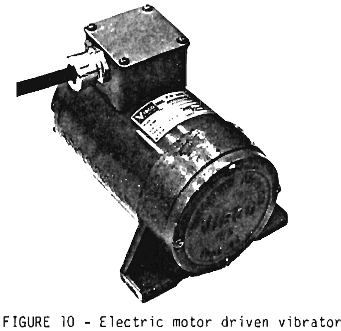
Electrical motor driven vibrators consist of an eccentric weight on a motor shaft. These can produce much higher forces, vibrate at one speed, are more expensive and subject to greater wear (Figure 10).
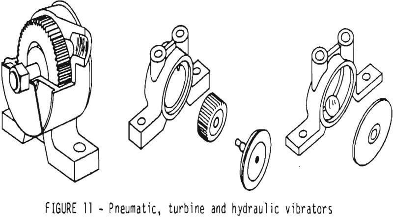
Pneumatic and hydraulic designs are similar, with differing power sources. These may use turbines with shaft mounted eccentric weights, or a hardened ball that spins in a circular race. These types have a wide range of produced force, are variable speed, relatively inexpensive, but are subject to wear (Figure 11).
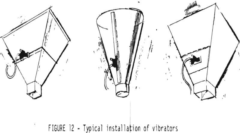
Vibrators are available in a number of mounting configurations and most common power sources. Portable ones are sold that can be moved from place to place and clamped to the bin, hopper or car as desired (Figure 12).
Sonic Fluidization
Discrete-frequency acoustic power horns (Figure 13) are recent introductions as bin and hopper accessories for eliminating and preventing material hang-ups. They have been used with flyash, kaolin dust.
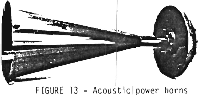
kaolin clay, lime, aluminum and iron oxide, and cement dust with report evaluated for unloading rail and tanker cars.
According to manufacturer’s literature, the new power horns, rather than generate a broad spectrum of sound, focus the sound power at a narrow frequency range, which delivers about twice the fluidizing power as conventional broad spectrum horns. The primary frequency selected (about 230 HZ) fluidizes the dry bulk material without vibrating the holding structure. One theory is that the sound vibrates the air rather than the dust particles, and that the energy is transmitted to the dust particles from the air, causing fluidization.
The installation site for the new power horns does not appear to be critical relative to potential bridging. The units are mounted above the product away from direct contact and require only compressed air and control wiring for operation. Low installation and maintenance costs are also given as advantages over mechanical accessories. Maintenance is limited to a metal diaphragm, making them very reliable.
An air cannon is a device that injects a large volume of compressed air through the bin wall into the vicinity of bridged, hung-up, or ratholed material. The force of the air expanding through the material breaks loose the build-up.
Material in almost any flowability classification can be moved by an air cannon, including sticky, wet, stringy and large lump material. Aeratable materials also may remain aerated, with improved flowability for a period of time.
All of these devices are, of course, pneumatically operated, and require a compressed air line (>100 psi) and an electric (solenoid) control system. Bursts may be automatic or on demand. General construction is a storage chamber to hold the compressed air, a solenoid or manual valve trigger, a directional control valve, and a discharge line to the bin (Figure 14). Discharging of the air is muffled by the bin contents so that little noise is heard. Inert gases can be used if air creates a hazard or degradation in the material.
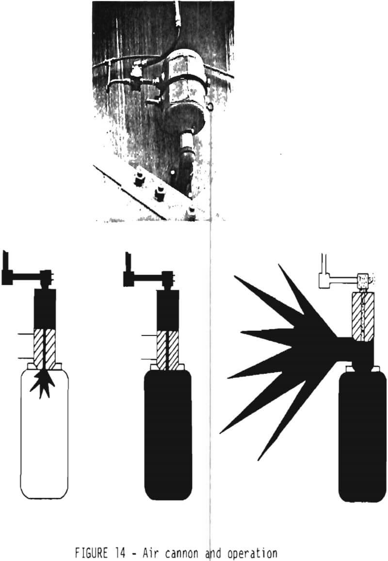
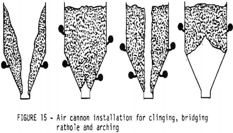
Proper installation of an air cannon is critical. The areas where hang-ups are occurring must be identified and the discharge properly placed, as discharging air will not affect a buildup when discharged above or below it.
Manufacturers have specific recommendations for the installation of their products; generally the cannon discharges are mounted above the hopper on the bin wall, and aimed toward the bin discharge (Figure 15). Because these devices are designed to break up large masses of materials, flow out of the bin may be erratic. One manufacturer recommends the use of a vibrator beneath the air cannon to even out the flow.
Some advantages of air cannons are:
- low air consumption,
- effective on almost all materials,
- quiet operation
- low maintenance.
Some disadvantages are:
- more expensive installation,
- high pressure air required,
- does not induce steady flow out of the bin,
- installation points are critical.
Internal Mechanical Flow Aids
Internal mechanical devices were some of the earliest techniques for inducing flow in low-flowability materials. Many of these were suspended and operated from the top of the bin, and included such things as large chains and suspended vertical beams with welded cross pieces, both of which were capable of vertical movement. Still an effective technique in dislodging hang-ups can be a full-height pipe or hollow section installed in the center of a bin and activated by a vibrator or mechanical/manual rotating device. The commercial internal mechanical flow-aids, however, concentrate on the material in the cone.
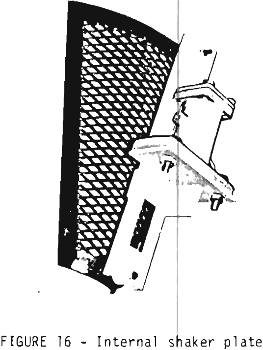
The internal shaker plate is an expanded mesh plate mounted on the inside of the bin cone in the area where the material tends to bridge. Two rigid bolts attached to the plate pass through the bin wall, through vibration isolated gaskets, and connect to a pneumatic shaker that moves the plate parallel to the bin wall. This motion breaks up bridges and keeps the material moving downward (Figure 16).
Expanding cushions are elastomer sheets bonded to steel plates and mounted in the bin cone. Air is forced through a fitting in the plate to expand the cushion. This lifts the material gently. The pressure is then released and the cushion deflates, allowing the material to fall. Pulsing the cushions gives an action similar to a vibrator.
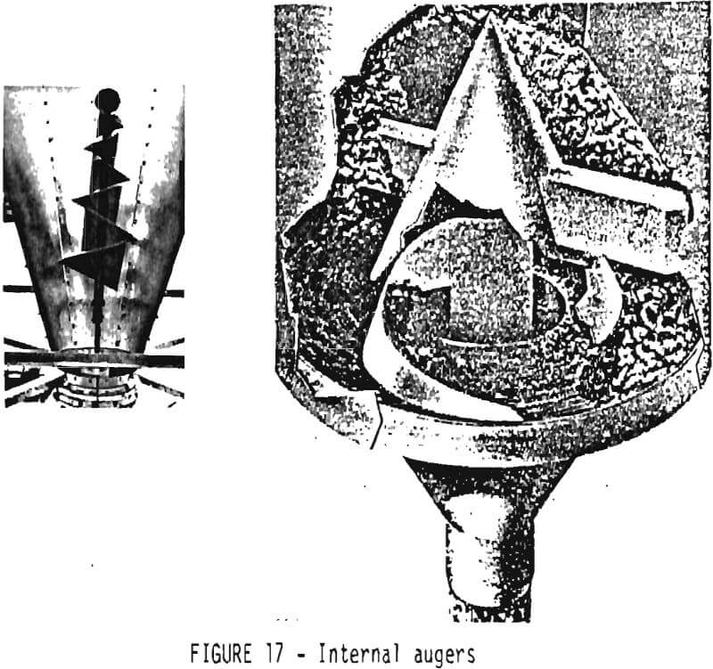
Internal augers mount inside the bottom of the bin. Long, small-diameter types “walk” around the bottom cone of the bin; short, large-diameter types mount vertically and rotate in place. The auger carries the material to a discharge port, with flow rate being a function of auger speed (Figure 17).
These systems are more positive than an outside mounted vibrator, but at additional cost. All work on low flowability materials.
Advantages of these systems are:
- move very difficult materials,
- quiet operation.
Disadvantages are:
- difficult installation (inside mounting),
- relatively expensive,
- may require air supply.
- maintenance or repair may be difficult.
Live Bin Bottoms
The active, or live, bin bottom is one of the newest techniques for inducing material flow from a bin. There are several variations, but they all consist of specially designed hoppers, suspended below and vibrationally isolated from the bin hopper, that can be vibrated to induce and meter flow of even the most sluggish materials.
Live bin bottoms are the ultimate in bin flow aids, and are accordingly priced. In many cases, however, their additional cost is recovered by the reduction in bin flow problems and their versatility in handling materials with diverse or changing flow properties.
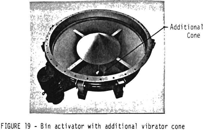
Bin Activators – The Bin Activator is the name given to a bottom hopper design which uses a baffle plate above the discharge cone to accept the weight of the overburden (Figure 18). The baffle plate is rigidly attached to the base hopper.
Flow is induced and maintained by vibrating the hopper and baffle plate using an external gyrator, sending vibrations into the
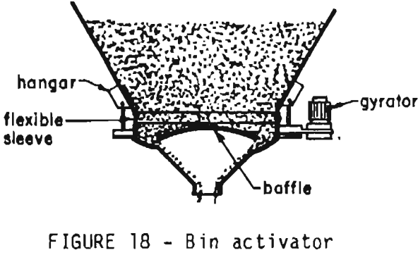
material on and above the plate. The material is thus metered through an annular space between the plate and hopper sides to the discharge outlet below with the discharge feed area seeing only loose, unpacked materials.
Figure 18 represents the more common design. For more sluggish materials, an additional vibrator cone is added beneath the main one to assist flow out of the bottom discharge (Figure 19). Another type vibrates only the center cone and vibrates vertically instead of axially. Further, the gap between the cone and the discharge can be pneumatically adjusted to control flow.
Installation of a bin activator on an existing bin requires cutting, off the bin cone and welding on a flange to which the active bottom is attached. Manufacturers’ recommendations must be followed in choosing an appropriate size in order to ensure a functional installation. In general, however, the bin activator size should increase in proportion to the bin diameter as material flowability decreases. For sluggish materials in smaller bins, the size may approach the diameter of the bin.
After installation, a trial and error period is usually necessary to determine the optimum on-off cycle of the vibrator for desired flow to minimize packing in the discharge area, especially if the discharge is being metered at some slower rate with an external feeder.
Vibratory Bin Discharger – The Vibratory Bin Discharger appears to be a substitute for the conventional bin activators, with the added capabilities of varying and stopping materials flow. Theoretically, it can replace a feeder and a slide gate, if such items are necessary parts of the bin system.
The Hogan Vibratory Bin Discharge is shown in Figure 20. It has a suspended hopper sealed to the bid hopper by way of a flexible
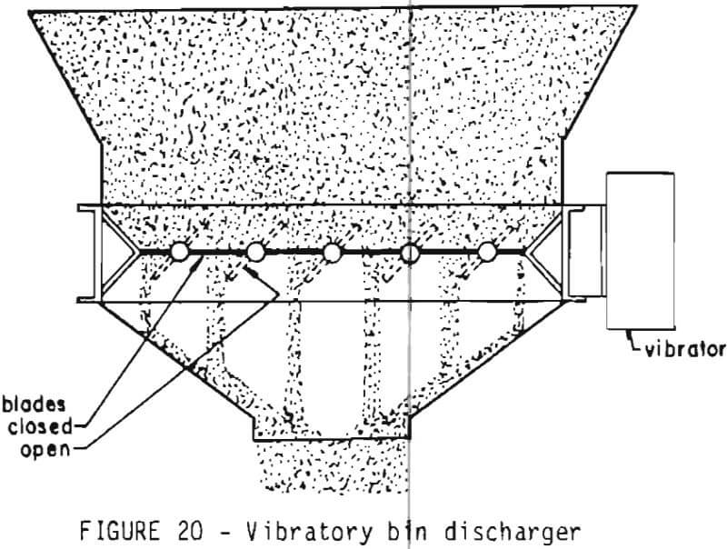
sleeve, and can be vibrated to induce flow similar to the bin activator units. Unlike the round bin activators, however, the unit is square or rectangular, dictating a similarly-shaped bin hopper, and contains a number of blades which are free to rotate through 90° from the horizontal (closed position) to the vertical (open position). The blades are all positioned similarly with a single control.
The vibratory action induces and maintains material flow through energy to the blades. With the blades fully closed, vibration is in the horizontal plane, thus minimizing packing of material immediately above. With the blades partially open, vibration is transmitted into the stored material, starting flow. If a significant size variation exists in the particles of the materials stored, according to manufacturer’s literature this type of bin discharger minimizes segregation in the discharge bin by achieving even flow over a larger bottom area.
Process signals can be used to control the bin discharge rate. Electric or pneumatic actuator systems for the blade positions can be used to automatically reposition the blades and thus increase or decrease the bin discharge rate in response to the signal. Depending on the material, 250:1 to 100:1 turndown ratios are reasonable, thus allowing considerable versatility in flows and materials to be stored.
Liners
Bin liners, installed on the inside of discharge cones, are a passive flow aid, working without external power sources. By reducing the wall friction in the area where a bridge forms, the material can’t generate the strength needed to form bridges as readily. Liners can also be combined with other flow aids, such as vibrators, allowing a smaller, less expensive vibrator to replace a larger one. Although they have the advantage of needing no operating power, they are susceptible to damage and sometimes expensive to install.
Types of liners available are many. Spray-on urethane coatings currently seem to be the most effective. They can be made very smooth, yet are abrasion resistant. Some other types are Teflon and other plastics, hard ceramic and polished stone tiles, and polished steel sheets. These may be permanently attached or replaceable.
Abrasion is the worst enemy of liners. A liner that is roughened, scored, cut or otherwise damaged is worse than useless, creating hang-ups where none existed before. Matching material abrasiveness and liner material is critical, since frequent replacement of liners is not cost effective and may require entering a bin to manually remove hang-ups before replacing the liner, eliminating the safety aspects of bin flow aids.
Liners may be used with almost any flow classification material. If the bin design is close to working, liners may provide the extra reduction in friction to turn a marginal bin into a free flowing one. With classification 3 or 4 materials, however, liners alone usually can’t make a poorly designed bin into a free flowing one.
General Installation
It should be noted that all bin flow aids may work too well; that is, increase product flow above the capacity of the hopper or bin outlet to discharge it, or above a desired flow rate. This may result in surging, flooding, or packing in the cone below the lowest active point of the bin flow aid. Further, the addition of a rotary feeder, shaker table, screw conveyor, or other metering device will also increase the likelihood of hanging up in the discharge tube. (One exception is aeration, as the material does not have to keep moving to maintain flowability.) As a result, many of these installations require some trial-and-error to achieve optimum operation.
After installation of the chosen flow aid, the system must be operated and the flow aid “adjusted” to desired flow results. This may include:
- adjusting vibrational amplitude and frequencies,
- adjusting air flow rates to aerators,
- determining cycling times on air cannons and vibrators,
- adding or moving vibrators.
The best overall guide to properly supply, install and time a flow aid system is an experienced, reputable manufacturer of these devices. This section of the manual is intended to provide an overview of the types of these devices and some general information on installation and operation, giving an operator with a problem the vital information of what the problem may be, what type of device may work, and who can supply it. The chosen vendor then has the responsibility of satisfying his customer with technical information, support and knowledgeable personnel .
Flow Aid Accessory Suppliers
The following is a listing, by types, of bin flow aid accessory suppliers. The listing is extensive, but by no means complete, nor does the order of listing designate any order of preference.
Aeration
Airnetics, Inc. – 200 North Island Ave., Batavia, IL 60510
Azo, Inc. – P.O. Box 181070, 4128 New Getwell Rd., Memphis, TN 38118
Ducon Fluid Transport – 840 First Ave., King of Prussia, PA 19406
Dynamic Air, Inc. – P.O. Box 43074, St. Paul, MN 55164
Fuller Company – P.O. Box 2040, Bethlehem, PA 18001
Material Control, Inc. – One Smoletree Plaza, Suite 115, North Aurora, IL 60542
Monitor Mfg. – Drawer AL, Elburn, IL 601:19
Vibrators
Dynapac, LTD. – 5340 Maingate Drive, Mississauga, Ontario Canada L4WlR8
ERIEZ – P.O. Box 586, Erie, PA 16512
Fluid Energy Processing & Equipment Co. – 153 Penn Avenue, Hatfield, PA 19440
Martin Engineering Co. – Route 34, Neponiet, IL 61345
VIBCO, Inc. – P.O. Box 8, Stilson Rd., Wyoming, RI 02898
Power Horns
Sonic Power Systems, Inc., P.O. Box 12785, Shawnee Mission, KS 66212
Fuller Company, P.O. Box 2040, Bethlehem PA 18001
A.S.E.A. Industrial Systems, Inc., 4 New King St., White Plains, NY 10604
Drayton Co., P.O. Box 820, Jacksonville, AL 36265
Analytec Inc., P.o. Box 810, Corrales, NM 87048
Air Cannons
Martin Engineering Co. – Route 34, Neponset, IL 61345
Monitor Mfg. Co. – Drawer AL, Elburn, IL 60119
Pulsonics Corp. – 777 Airport Road, Lakewood, NO 08701
VIBCO, Inc. – P.O. Box 8, Stillson Rd., Wyoming, RI 02898
Fluid Energy Processing & Equipment Co. – 153 Penn Avenue, Hatfield, PA 19440
Internal Mechanical
AZO, Inc. – P.O. Box 181070, 4128 New Getwell Rd., Memphis, TN 38118
Brock Mfg. Co. – Milford, IN 46542
IFE Systems – 370 Franklin Turnpike, Mahmah, NY 07430
LAIDIG, Inc. – 14535 Dragon Trail, Mishawaka, IN 66544
Thayer Scale Co., Hyer Industries, Inc. – Pembroke, MA 02359
VIBCO, Inc. – P.O. Box 8, Stillson Rd., Wyoming, RI 02898
Pulsonics Corp. – 777 Airport Road, Lakewood, NJ 08701
Martin Engineering Co. – Route 34, Neponset, IL 61345
Monitor Mfg. – Drawer AL, Elburn, IL 60119
Live Bin Bottoms
AZO, Inc. – P.O. Box 181070, 4128 New Getwell Rd., Memphis, TN 38118
Carman Industries – 1005 West Riverside Or., Jeffersonville, IN 47130
Kinergy Corp. – 4821 Jennings Lane, Louisville, KY 40218
METALFA8, Inc. – 140 Woodland Ave., Rochelle Park, NJ 07662
ORTHOS, Inc. – 5001 Lincoln, Box 520, Lisle, IL 60532
Solids Flow Control – 4 Flair Field Crescent, West Caldwell, NJ 07006
Vibrascrew, Inc. – 755 Union Blvd., Tutowa, NJ 07511
Pneubin Corp. – P.O. Box 554, Palos Heights, IL 60463
Thayer Scale Co., Hyer Industries, Inc. – Pembroke, MA 02359
Liners
Devcon Corp. – 30 Endicott St., Danvers, MA 01923
Dupont Co. – Room X39752, Wilmington, DE 19898
AZO, Inc. – P.O. Box 181070, 4128 New Getwell Rd., memphis, TN 38118
Brock Mfg. Co. – Milford, IN 46542
Carman Industries – 1005 West Riverside Drive, Jeffersonville, IN 47130
IFE Systems – 370 Franklin Turnpike, Mahmah, NJ 07430
Klnergy Corp. – 4821 Jennings Lane, Louisville, KY 40218
LAIDIG, Inc. – 14535 Dragon Trail, Mishawaka, IN 46544
METALFAB, Inc. – 140 Woodland Ave., Rochelle Park, NJ 07662
Monitor Mfg. – Drawer AL, Elburn, IL 60119
ORTHOS, Inc. – 5001 Lincoln, Box 520, Lisle, IL 60532
Solids Flow Control – 4 Fairfield Crescent, West Caldwell, NJ 07006
Vibrascrew, Inc. – 755 Union Blvd., Tutowa, NJ 07511
Bin Safety
In the FOREWORD, we stated that the primary purpose of this manual is to promote bin safety; that one of the ways to do this is to minimize the necessity for a worker entering a bin by good bin design; and we gave guidelines on how this may be accomplished. Even if you, the engineer in charge, and your company have followed these guidelines to the best of the present state-of-the-art, your responsibility to your workers does not stop here. With even the best of designs there are times when material flow or other bin problems will occur, and it will become necessary to enter a bin. When this occurs, it is your responsibility that the worker observes all regulations and uses procedures that will expose him to minimum danger.
Figure 21 is a newspaper account and picture of a bin accident in 1983. This victim survived. Just as often, however, the report would have read, “the victim was discovered dead with his feet protruding from the base of the bin, when flow from the bin stopped and workers investigated to find the cause.”
Bin fatalities are still too common, and avoidable if safety regulations are observed. In a 5-year period, between 1975 and 1979, 24 such fatalities occurred. Like the potential victim above, Federal safety regulations were ignored.
Further analysis of the accidents revealed the following:
- No victims observed all Federal safety regulations.
- Only 4 victims wore safety belts.
- Only 1 victim had a second person tending his safety line.
- Thirteen victims entered the bin unknown to others.

- Fourteen victims fell through an encrusted surface and were buried. Five were assumed to have fallen from above.
- Seven victims were initially found alive, but could not be extracted in time.
The victim that wore the safety belt and had a second person tending his line failed to shut off the bin conveyor equipment; and when the crust on which he was standing gave way, he fell through and could not be pulled out by his attendant. When the attendant went for help, the victim was pulled into the discharge opening.
It should be emphasized, not one bin fatality occurred in this period in which the victim observed all Federal safety regulations.
And What Are Those Federal Safety Regulations?
There are three Federal safety regulations governing the actions of workers in and around bins. These are:
- 30CFR 56.15-5 – “Mandatory. Safety belts and lines shall be worn when men work where there is danger of falling; a second person shall tend the lifeline when bins, tanks, or other dangerous areas are entered.”
- 30CFR 56.16-2(a) – “Mechanical devices should be employed so that during normal operations persons are not required to enter or work where they are exposed to entrapment by caving or sliding of materials.”
- 30CFR 56.16-2(c) -“No person shall enter the facility until the supply and discharge of materials have ceased and the supply and discharge equipment is locked out.” “Second person shall be stationed where the lifeline is fastened and shall constantly adjust it or keep it tight as needed, with minimum slack.”
Bringing the Federal safety regulations to the attention of your workers is just the bare minimum of your responsibilities. One could assume that a significant percentage of bin fatalities just discussed knew the Federal regulations, and ignored them either for expediency or because of a lax company attitude towards safety.
What Else Can You Do?
Your company should make every effort to keep these violations to a minimum. The following are recommendations that should be considered:
- Make bin systems as trouble-free as possible – Use proper bin designs and bin flow accessories for the material to be handled. Keep records of bin problems so that the potential danger points can be identified and corrected.
- Improve your SAFETY IMAGE – Safety is more an attitude problem than a problem with actions. This attitude must be emphasized at every level of company management, especially the production supervisors.
Maintain clean and inspected safety equipment convenient to the work site and train your personnel on the correct procedures and the safe way to handle a bin problem. Reinforce this training with frequent reminders, and penalties, if these procedures are ignored. - Limit access to bins – Whenever possible, padlock access doors to bins, and keep the key with supervision. If access is needed, the supervisor can make certain that safety rules are observed, and recommend safe courses of action.
- Post signs on bin accesses – If limiting bin access is not feasible, post highly visible warning signs on all bin accesses.
- Provide warning lights and equipment lockouts – Whenever possible, provide warning lights and equipment lockouts. These could be made automatic with an access door opening, or at least convenient when a worker must enter a bin area.
When A Bin Must Be Entered
If material flow problems, cleaning, or repairs require that a bin be entered, some common sense guidelines should be observed:
- Observe all Federal safety regulations – Lock out conveyor equipment, wear suitable safety clothes and harness, and have a second person tend your safety line. Wear a safety harness rather than a belt if possible, and make certain that the safety line is in good repair and maintained taut and secure by the attendant. The attendant should have safe, secure footing.
- Approach the problem from the top – Don’t go below material clinging to the bin sides, or to the base of sloping material. When initiated, some materials can quickly engulf potential victims before evasive action is possible. Be especially careful in probing bridged material up through bin discharge openings. Sudden material surges have damaged chutes, with fatal consequences.
- Beware of walking on encrusted surfaces – Voids underneath are potential death traps should the crust give way. If such action must be taken, maintain a taut and secure line to the worker at nearly a completely vertical angle so that if footing is lost, the potential vertical drop for the worker is limited to only 2 or 3 feet. Safety pulleys, limiting the free fall of workers, are advisable.
- Handle the problem at length if possible – Use mechanical accessories, air lances and long probes rather than picks and shovels.
- Do not activate bin accessory equipment with the worker in the bin – Sudden material surges are powerful and dangerous, and could cause structural bin damage with potential injury to workers in or near the bin.
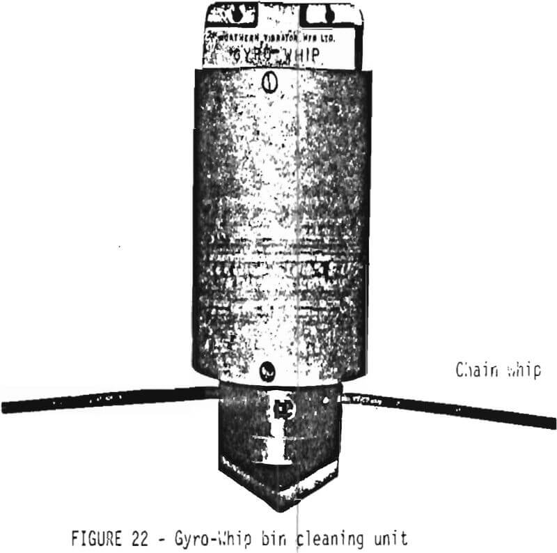
A New Bin Cleaning Tool
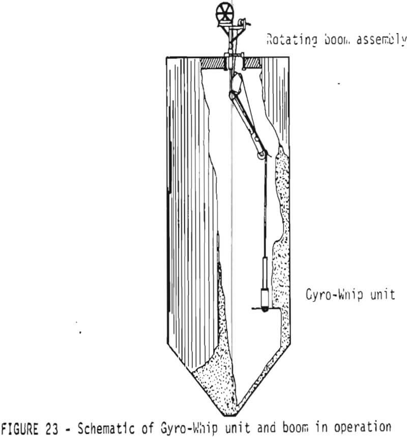
A portable, remote-controlled tool developed specifically for clearing build-up of bulk materials in bins and other storage units without requiring bin entry by workers, has recently come on the market. Called the Gyro-Whip System, the tool, shown in Figure 22 is manufactured by Northern Vibration Manufacturing Limited. It consists of a compressed-air driven motor which rotates two cable or chain whips at high speeds, and a boom unit for positioning the tool within the bin (Figure 23). Developed initially for the grain industry, the system has recently been used for cleaning cement, cement klinker and copper, nickel and zinc ore products from bins and silos.
The positioning boom unit is lowered through the manhole entrance and assembled by a two-man crew, who remain outside the bin at all times. The Gyro Whip unit, which is supported by its air hose, can then be raised, lowered and moved about the interior of the bin. It has a specially designed nose cone that aids in removing loose material from its path. The force created by the whips hitting the solid material is counteracted by the gyroscopic action produced by the motor.
The boom has a reach of 21 feet, and can be rotated 360°. It thus can clean bins up to 40 foot diameter from a center opening.