Table of Contents
Terms such as in situ mining, in situ leaching, solution mining, borehole mining, and slurry mining have been used in different ways to describe a wide range of mining operations where a commodity is usually extracted remotely by activities that are conducted from the surface. As used in this publication, in situ mining is a general term that includes both leaching and borehole (or slurry) mining methods. In situ leaching does not include dump or heap leaching where the ore is blasted and/or dug and placed in areas specially prepared for leaching, but is reserved for the process where chemical solutions are circulated through the ore body. Although the ore may be blasted to increase permeability for in situ leaching, it is not transported. The term borehole mining is used for the process where a hydraulic jet is used to slurrify a mineral commodity which is then pumped to the surface through a pipe.
In situ mining has been characterized as an extraction method having significant potential for increasing productivity and extending reserves. Leaching and borehole mining can lower the cutoff grade of ores having appropriate characteristics. Other advantages attributed to in situ mining include low capital costs, quick return on investment, minimal effects on the environment, and improved safety. As part of its mission to assure that private industry can produce a substantial share of the Nation’s mineral needs in a manner that does not degrade the environment, the Bureau is conducting research to improve in situ mining technology. Although research is underway at the Bureau’s Metallurgy Research Centers (principally Salt Lake City and Reno) to improve metallurgical processes for dump, heap, and in situ leaching, this paper will be restricted to research conducted, by the Bureau’s Mining Research Branch.
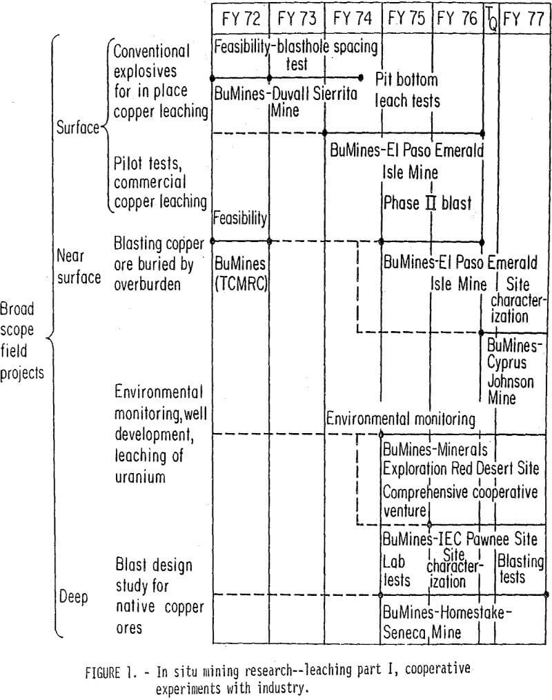
In situ mining research started at the Twin Cities Mining Research Center in FY (fiscal year) 72 with a study to evaluate the feasibility of using conventional chemical explosives to fragment a low-grade copper ore body in preparation for in situ leaching (fig. 1). In FY 73, this research effort was expanded into a “field evaluation of various blast designs and eventually helped form the basis for establishing (in FY 76) a separate subprogram devoted to in situ mining at the Twin Cities Mining Research Center as part of the Bureau’s Advancing Metal-Nonmetal Mining Technology (AMNMT) program.
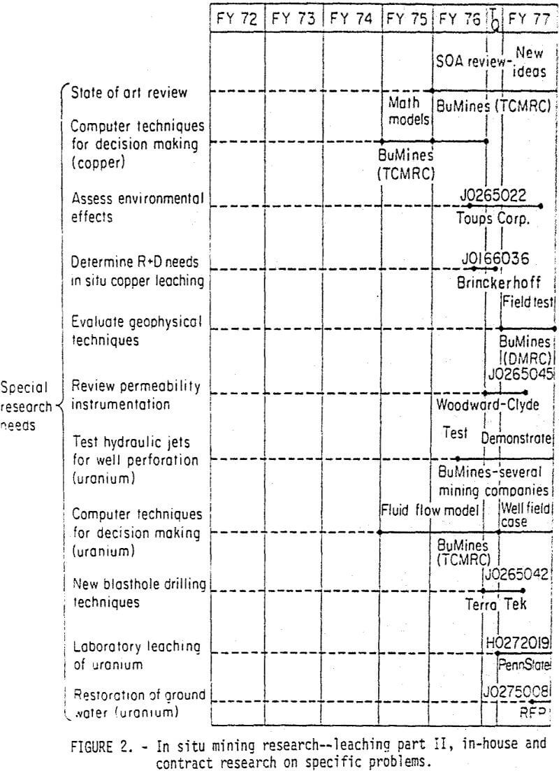
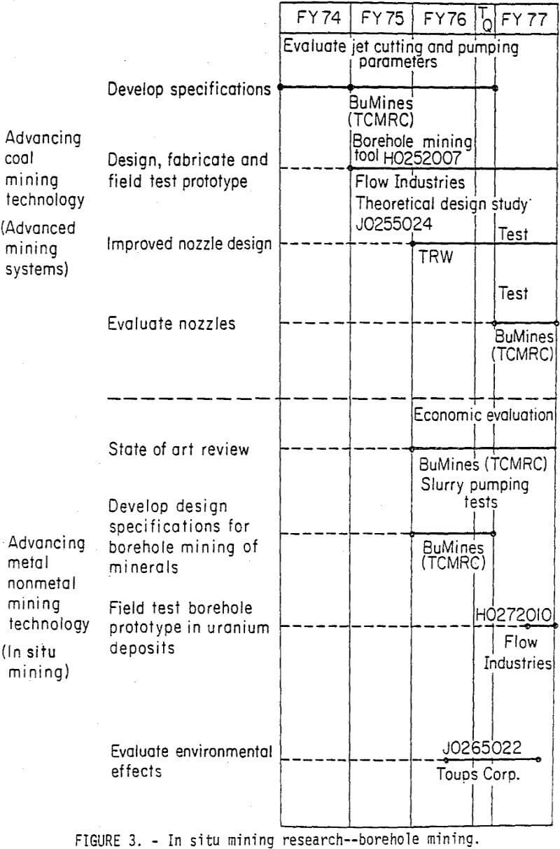
The in situ mining subprogram and the previous in situ mining research conducted at TCMRC include projects in both leaching and borehole (or slurry) mining. Research in leaching has been conducted under broad scope cooperative ventures with mining companies (fig. 1) and also as more specific investigations of high-priority problems (fig. 2). The progress on the borehole portion of the AMNMT subprogram has been significantly aided by equipment development work funded under the Bureau’s Advancing Coal Mining Technology program (fig. 3). Major emphasis in the AMNMT borehole mining research is placed on identifying the economical potential of this technology for critical mineral commodities such as uranium. Both the leaching and borehole portions of the In Situ Mining subprogram contain projects which review the state of the art (SOA) of the respective mining methods. In addition to keeping abreast of the developments in these fields, the SOA projects assess the economics for applying the technologies to new commodities. As a result of interaction with industry, the SOA projects generate ideas for new research projects. Results of the SOA work will be disseminated to the public through periodic Bureau publications, such as Information Circulars and Reports of Investigation and other documents. For example, under the leaching SOA project, the Bureau has developed an extensive bibliography which is continually updated and is available to the mining industry and the general public upon request. Parties interested in obtaining copies of the updated bibliography on leaching should contact W. C. Larson, Twin Cities Mining Research Center, Bureau of Mines, P.O. Box 1660, Twin Cities, Minn. 55111 (612-725-3464). Parties interested in specific details on the borehole mining research conducted by the Bureau should contact Dr. George Savanick (612-725-4543), also at the Twin Cities Mining Research Center.
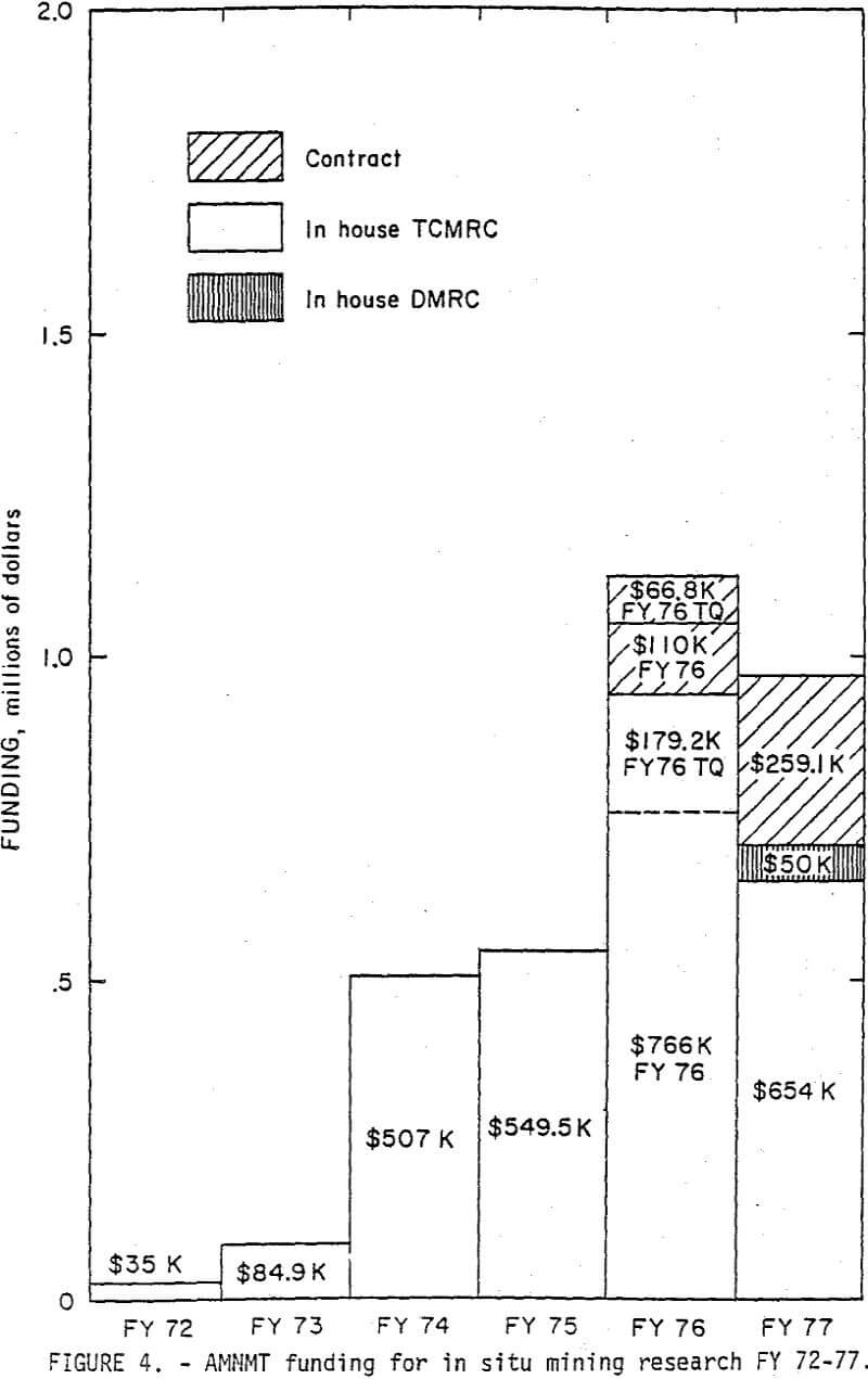
Figure 4 shows the AMNMT funding for in situ mining research during the period FY 72-FY 77. The high funding level for FY 76 was caused by the Federal Government’s shift to a new fiscal year framework starting in October rather than July. The program funding has been projected at about $1 million per year for the next couple of years.
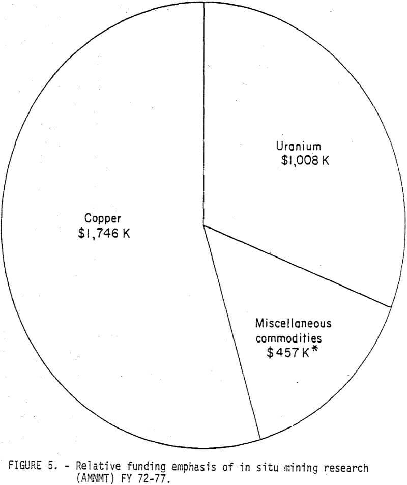
Until FY 75 all the in situ research projects were directed toward copper leaching. During FY 75 the first experimental work on in situ uranium leaching was conducted in cooperation with Minerals Exploration Co., at its site in the Red Desert area of Wyoming. The relative percentage of research funds directed toward solving problems in the in situ uranium leaching field has increased sharply during the recent years, and presently the proportion of the total funds spent on uranium-related work has grown to about one-third of the total (fig. 5). The trend toward a heavier emphasis on the technologies for In situ extraction of uranium is expected to continue as the problem of maintaining an adequate supply of uranium to fuel the Nation’s nuclear reactors becomes more serious.
The ultimate goal of the Bureau’s in situ mining subprogram is to accelerate the development and transfer to industry of improved techniques for the in situ extraction of ore deposits that would otherwise not be mined, thus expanding the Nation’s supply of critical mineral commodities.
In Situ Leaching Copper
The leaching portion of the in situ mining program (particularly for copper) is divided into three broad depth ranges: surface, near surface, and deep (fig. 1). Most of the copper ore bodies in the surface category are above the water table, and little, if any, overburden covers the ore. The near-surface deposits may or may not be below the water table, but a layer of overburden covers the ore body. Because a heaving action is difficult to obtain in these near- surface deposits, the problem of obtaining sufficient permeability enhancement by blasting is more complex than in the surface case. Research in the surface and near-surface cases is discussed under the heading of shallow deposits.
The deposits characterized as deep are buried by such thickness of overburden (> 1,000 ft) (305 m) that natural permeabilities of the formation are very low. In this case, one potentially feasible mining method is to enter the ore body and excavate swell space to receive the remaining rock mass which is blasted. Extraction proceeds on a hybrid scheme where the rich portions of the ore body are mined conventionally and the leaner portions are exploited with the in situ technique.
Shallow Deposits
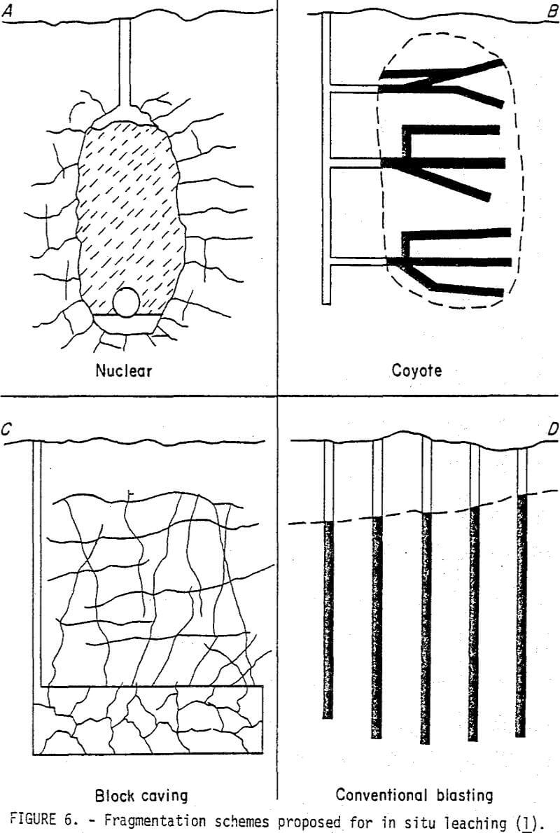
The Bureau’s first project in the in situ copper leaching field was a feasibility study to evaluate the technical and economic problems encountered by industry and to recommend a course of action. Figure 6 A-C shows the three blasting schemes that had been proposed for use of the nuclear device (fig. 6-A) or were being used for in situ leaching in operations such as Ranchers Old Reliable project near Mammoth, Ariz., (fig. 6-B) and for block caving and leaching in mines at Ray and Miami, Ariz., (fig. 6-C). The Bureau’s initial work evaluated the fragmentation scheme shown in fig. 6-D, where large-diameter (> 9 in) (> 22.9 cm) vertical bore-holes were used with AN-FO (ammonium nitrate-fuel oil) or slurries to fragment the ore zone. Preliminary calculations showed that the vertical blasthole concept was competitive in cost with employing a nuclear device and of course avoided the political and environmental problems associated with that energy source. The largest question in the economic picture involved the blasthole spacings that would have to be used to achieve adequate fragmentation in this blasting condition where the explosive is severely confined, and the Bureau’s research was focused on that problem.
Blast Design—Fragmentation Research at Duval’s Sierrita Mine
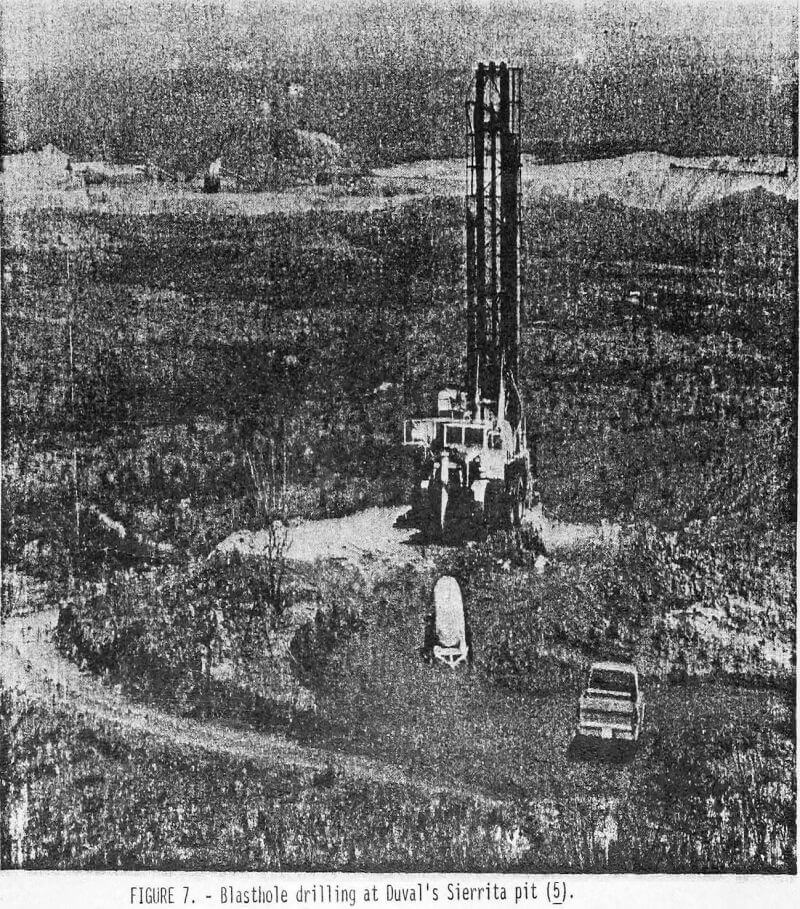
The first steps toward answering the blasthole spacing question for conventional explosive fragmentation were undertaken by the Bureau in cooperation with the Duval Corp. The target ore zone was located in a porphyry copper molybdenum deposit near the company’s Sierrita pit south of Tucson, Ariz., (fig. 7). Ten 9- inch (22.9-cm) diameter blastholes containing a total of 17,400 lb (7,900 Kg) of aluminized slurry were fired in a special pattern which allowed the Bureau to evaluate fragmentation from three different blasthole spacings: 15 ft (4.6 m), 20 ft (6.1 m), and 25 ft (7.6 m).
In comparing the drill core data obtained from the blasted regions of the Duval test site with fragmentation results reported for the in situ leaching blasts at the Old Reliable and Big Mike mines, the Bureau determined that all three blasthole spacings produced fragmentation comparable with that produced by these production blasts. The Bureau’s test blast produced an average fragment size that was less than the average 9-inch-diameter fragments reported at the Big Mike mine and within the 9-inch or less range obtained at the Old Reliable.
The Bureau used acoustic logging techniques to evaluate the deterioration in structural quality of the postblast versus the preblast rock and determined that the blast-induced damage in the core fragments had been significantly better in the 15- and 20-ft spacings than it had in the 25-ft spacing (7.)- The 25-ft spacing, however, did appear to generate sufficient cracking in spots to also hold potential for use as a design parameter for exceptionally low grade ores that have poor structural quality initially.
Leaching Experiments at El Paso’s Emerald Isle Mine
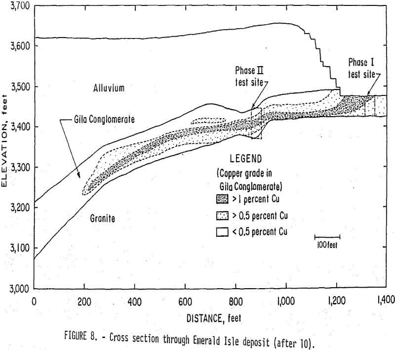
Although the Bureau’s fragmentation experiment at Duval’s Sierrita mine had indicated that conventional explosives in vertical boreholes at spacings of 15, 20, and even 25 ft (4.6, 6.1, and even 7-6 ra) could adequately break up a buried ore body for in situ leaching, no leaching had been conducted. Because value recovery is one of the important unanswered questions in the in situ copper leaching area, the Bureau sought further cooperation from the mining industry to actually prepare and leach a site. This phase of the Bureau’s program was undertaken in cooperation with El Paso Mining and Milling Co., at their Emerald Isle mine 15 miles northwest of Kingman, Ariz. The ultimate goal of the Bureau’s cooperative work at the Emerald Isle mine was to demonstrate that in situ leaching methods could be used to economically exploit 200,000 tons (18.1 x 10 7 Kg) of ore in the pit bottom and 1,500,000 tons (136 x 10 7 Kg) of ore located near the flanks of the pit but buried under 200 ft (61 m) of overburden. In addition to the paper presented by D’Andrea and Runke at the joint MMIJ-AIME meeting in Denver, Colo., September 1-3, 1976, the Bureau plans on publishing a comprehensive Report of Investigations (RI) describing the Emerald Isle work. The initial test (Phase I) Involved explosively fracturing 15,000 tons (13.6 x 10 6 Kg) of ore in the pit bottom which was then leached (fig. 8). Based on the success of the Phase I test, El Paso also leached part of the ore in the pit bottom. The remaining experiments conducted under the cooperative agreement involved assessment of the fragmentation and permeability enhancement resulting from two blasts detonated by the Bureau in the Phase II area buried by 200 ft (61 m) of overburden.
During leaching of the Phase I area, effluent copper grade averaged 0.562 gram/liter, and a total of 29,000 lb (13,200 Kg) of copper was produced by cementation on scrap iron.
After the completion of the Phase I leach test, El Paso commenced leaching of approximately 100,000 tons (9.1 x 10 7 Kg) of ore in the pit bottom. The leaching continued for 190 days after the December 1971 startup date. Because the company believed the natural permeability of the Gila Conglomerate in the pit bottom might be sufficient to circulate the leaching solutions, the ore was not blasted. Although the grade of the effluent solutions was 0.646 gram/liter, low flow rates eventually forced El Paso to suspend leaching activities in the pit bottom to drill and blast the ore in an effort to increase the permeability and boost the flow rates. Some blasting was done, but before this step in ore body preparation could be completed, the company decided to close the Emerald Isle mine.
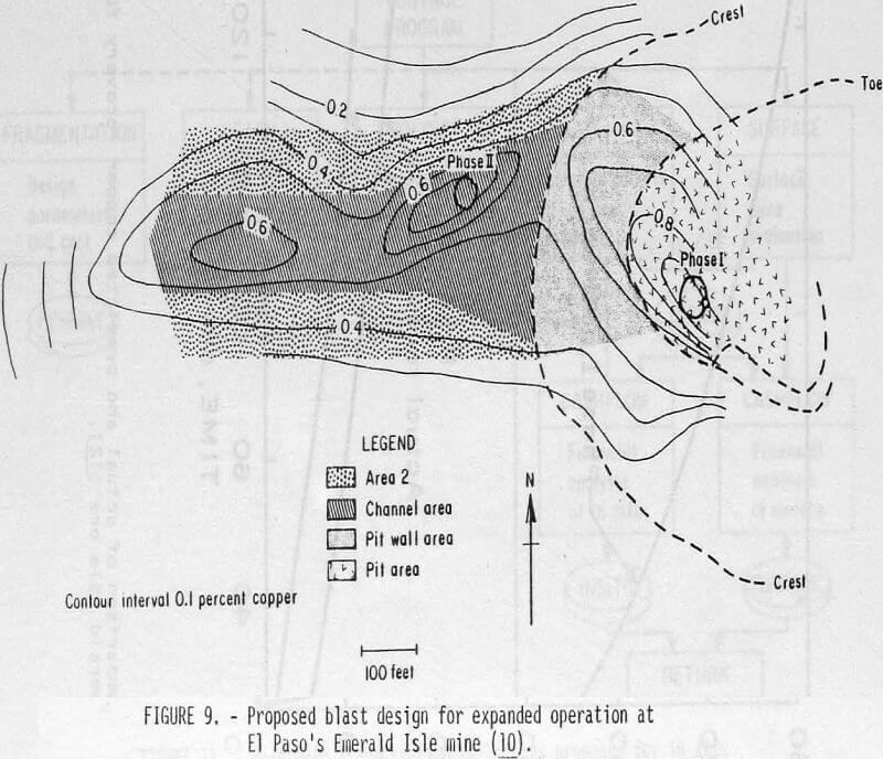
Although El Paso’s decision to terminate operations at the Emerald Isle mine shelved the Bureau’s goal of demonstrating a production-scale in situ leaching operation for low-grade copper ore buried under 200 feet of overburden, detailed plans had been formulated. Figure 9 shows the final product of this exercise—an approach that would blast and leach high-grade ore first, with successive panels of lower grade material added as the project was expanded. The first area would include ore in the pit bottom, under the pit walls, and under 180 to 250 ft (55 to 76 m) of overburden along a channel extending 700 ft (217 m) from the crest of the pit. The channel would follow the high-grade copper mineralization. The second step would be to leach lower grade ore along the flanks of the 700-ft (217-m) channel.
This stepwise plan has several advantages which may be exploitable in other similar geologic situations:
- Initial leaching is in the higher grade ore. Lower grade areas need not be added unless the first area yields good results.
- Because the solutions would migrate downdip from the pit bottom to the recovery wells, the leach solutions would be in contact with the ore for a longer time and should produce a higher grade solution.
- Because the initial channel would be weakened by the action of leach solutions, a second blast which fragments lower grade ore could be designed at a lower powder factor than the first.
- Blasting of the second area should shake up the first area and restimulate copper production.
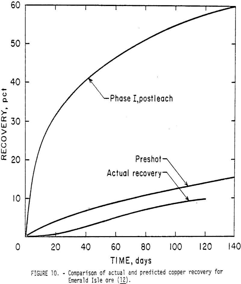
One of the important obstacles to wider application of the in situ leaching method in copper mining is the uncertainty in predicting final recovery. To help resolve some of this uncertainty, the Bureau used data from the Sierrita and Emerald Isle experiments as input to a computer program which predicted copper recovery as a function of fragment size and leaching parameters. This work, presented at the 17th U.S. Symposium on Rock Mechanics, demonstrated that the actual copper recovery fell short of the recovery predicted by the computer techniques (fig. 10). In addition to the degree of overestimation inherent in the program, the fragment sizes obtained using a double-barrel wireline system were probably smaller than those present in the rock mass; hence higher recoveries would be predicted. Improvements in computer simulation capability plus use of core drilling techniques, such as a triple-tube core barrel with a split inner tube, that do not disturb the core as much as other methods should enhance the accuracy of predicting the upper bounds of copper recovery from proposed in-situ leaching operations. Obviously if the economic value of the copper recovery predicted with these techniques (an upper boundary) does not exceed the costs of the project by a significant factor, the ore body should be rejected as an in situ leaching target.
Containment of Leach Solutions at Cyprus Mines Corporation’s Johnson Mine
After the untimely termination of the cooperative agreement with El Paso Mining and Milling Co., for research at the Emerald Isle mine, the Bureau canvassed the copper mining companies in the Southwest to find a new cooperator. Because of the depressed price for copper, interest was low; however, the Bureau succeeded in obtaining a cooperative agreement with Cyprus Mines Corp., for work at their Johnson mine. The project objectives are to demonstrate the economic advantages of in situ leaching for extracting low-grade ore from the fringes of Cyprus’ open pit mine. One of the most difficult problems under evaluation is that of solution containment. The ore body is above the water table, and several highly permeable zones intersect the area, targeted for leaching. A test blast was detonated during the last half of FY 77, and water circulation studies are underway to assess the ability to contain leaching solutions. As a followup to a successful test, Cyprus and the Bureau plan to conduct pilot- scale leaching in FY 78.
Mathematical Modeling
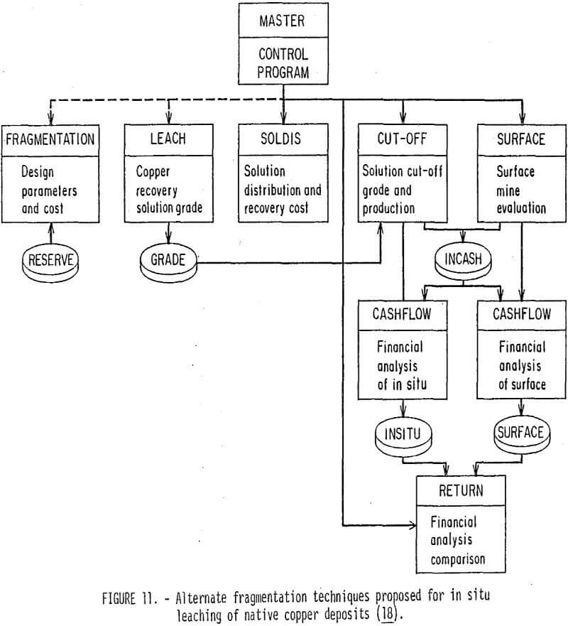
The Bureau’s work on computer modeling of in situ copper leaching, started in FY 75 (fig. 2), is summarized by a Ph. D thesis and two outside papers describing key portions of the overall computer program. As formulated in the thesis, the computer model consists of eight programs—ore reserve, fragmentation, leach, SOLDIS (solution distribution and recovery cost), cutoff, surface, cash flow, and finance (return)—that are designed to run separately, but could be combined by a master program (fig. 11).
An ore reserve model developed by White was used in this application to determine the geological parameters of the ore body to be investigated. The other programs calculate various operating parameters and/or costs. For example, the fragmentation program calculates the cost for either a coyote or a vertical blasthole system, while the leach program simulates the leaching of a typical unit of the copper oxide ore column and calculates factors such as the percent of copper recovered, the grade of the effluent solution, and the grade of the ore column as a function of time, acid concentration, and geologic parameters.
Based on the interest of the mining industry for use of this model, the Bureau plans to publish more details of the model as RI’s.
Deep Deposits
The portion of the Bureau’s in situ mining research dealing with an ore body that is too deeply buried to be fragmented with vertical blast holes from the surface was conducted in an underground mine In Upper Michigan’s Keweenaw Peninsula. This old mining district is famous for its rare occurrence of native copper, which is found in two types of rocks – lava flows (amygdaloid) and sedimentary deposits (conglomerate). A significant amount of copper remains in the mined-out areas in shaft and stope pillars, old stopes filled with low-grade ore, and low-grade remnants left in hanging and foot walls. Other deposits, never mined, also constitute a sizable reserve.
Because of the high costs associated with conventional mining and milling, elevated prices for copper have never stimulated the economics of this area to its former levels. Still, the native copper deposits of the Keweenaw were worked continuously from the l840’s to 1968 when Universal Oil stopped mining operations at its Calumet Division. In 1972, Shoemaker proposed that the deposits of the Keweenaw area might be reevaluated as targets for in situ leaching using a modified version of the Benedict process, a technique using cupric ammonium carbonate as a lixiviant, that was patented in 1915 by C. H. Benedict and used to treat millions of tons of tailings. Shoemaker’s suggestion of turning the entire copper-bearing vein structure of the Keweenaw Peninsula into one huge in situ leaching field represents an exciting concept. Implementation would, of necessity, have to be a slow, gradual process which would evaluate the numerous problems before leaching could be instigated on such a grand scale (or even on a small one).
Site Characterization and Fragmentation Assessment at Homestake’s Seneca No. 2 Mine
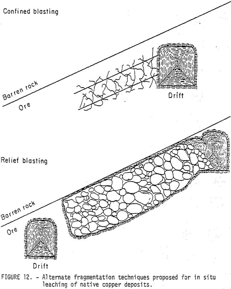
The Bureau’s research evaluated the feasibility of developing blocks of virgin ore for leaching, rather than leaching existing stopes filled with rubblized gob. The project was a cooperative venture with Homestake Mining Co., as part of Homestake’s agreement with Universal Oil Co., to work and evaluate mineral properties in the northern half of the Keweenaw Peninsula. A service contract was also awarded to Michigan Tech’s Institute of Mineral Research (IMR) to perform.laboratory “vat” leaching tests and porosity and permeability tests in the mine. Two basic approaches were originally conceived for fragmenting deep ore bodies for leaching—confined blasting from drifts, and blasting to relief provided by raises or other mine development openings (fig. 12). Because of the depressed market for copper at the time the cooperative work was conducted, emphasis was placed on the low-cost methods of circulating leach solutions through the ore body (confined blasting).
Part of the Bureau’s initial work on deep leaching of native copper deposits (FY 75) involved laboratory experimentation on a new technique for leaching the ore broken in a rubblized stope similar to the configuration shown in figure 12. The normal scheme for leaching ore in this configuration would involve flooding or downward percolation of leachant to contact the broken ore. Because of the large volume of leachant required for flooding, the cost is substantial. Moreover, in case an unexpected fissure is encountered, the flood leaching case would risk considerable loss of reagent with concomitant financial loss and potential threat to ground water. In addition, some of the leaching schemes proposed for the deeply buried ore deposits have involved plans for solution collection in drifts below the broken ore. Because a method of contacting fragmented ore in a generally upward or horizontal advancement appeared to have value, the Bureau developed and laboratory-tested a method for passing reagent-carrying foam through a rubblized ore column using air or other gas pressure. The key to the process is to incorporate a surfactant (surface reactive agent) in the leaching solution. The use of gases lighter than air, such as helium or helium-air mixtures, as foam carriers increases the traverse speed through the broken ore. The leaching process- can thus be carried out cyclically, with foam-up and drain-down cycles, or continuously, with the drain-down occurring at the periphery of the mass. This foaming technique may reduce channeling of the reagent flow patterns in a fragmented ore body, a potential benefit of the technique which must be verified in field experiments. Further tests may also be necessary to determine whether the surfactants are compatible with the leaching solutions and with the metallurgical processes used to recover the minerals from the solution.
The test site chosen by Homestake and the Bureau was on the third level of the Seneca No. 2 mine, near Mohawk, Mich. The copper mineralization at the Seneca Mo. 2 occurs in the amygaaloidal top of the Kearsarge basalt, which dips at an angle of 37° in the general direction of Lake Superior. Although the project activities were to be conducted only 350 ft (107 m) below the surface, the mine had been abandoned since the late 1950’s, and Homestake had to spend considerable time and money to refurbish the shaft and surface facilities before the test drift could be prepared.
The first step in analyzing the baseline conditions at the test site was to core-drill selected zones of the hanging and foot walls. The cores were analyzed for fractures, and later the holes were used to measure the natural permeability, porosity, and fracture characteristics of the amygaaloidal basalt. These data were used to (1) evaluate the possibility of circulating fluids without blasting, and (2) assess the relative effectiveness of different blasthole spacings In fragmenting the ore body.
The natural permeability of the formation ranged from 0 to 1.5 millidarcys (1.5 ft/yr [0.46 m/yr]), with an average of about 0.04 millidarcy. Effective porosity measurements, a way to estimate the length of the paths over which the pores in a rock are interconnected, showed that the pores were interconnected for an average of only 1 inch (2.54 cm) away from the core hole. These tests demonstrated that the formation had no potential for being leached without blasting.
Accordingly, the Bureau evaluated the fracturing and permeability enhancement generated by blast patterns (3-in [7.62-cm] diameter blastholes) with burden-to-blasthole-diameter ratios of 10, 14, and 18. A slurry blasting agent was used to provide a 20-ft (6.1-m) powder column. The remaining 20 feet of hole was filled with water. The effectiveness of each blasthole spacing In fragmenting the rock was evaluated with postshot core holes drilled in the center of each triangular pattern. Fracturing in the core was then compared with that in the preshot core; the permeability was also then determined in the postshot core holes for comparison with preshot measurements. Dyes were also injected into the formation after the blast to identify fracture zones capable of transmitting fluids.
The permeability changes created by the blast fracturing were disappointingly small. Even with injection pressures of 80 psi (5.51 x 10 5 N/m²), very little fluid could be pushed from one hole to the next. Because permeabilities of at least 500 ft/yr (152 m/yr) or 500 millidarcys are desired for leaching, and since the best permeability achieved with the close spacings was only 40 ft/year (12.2 m/yr) or 40 millidarcys, the Bureau concluded that confined blasting simply did not create enough permeability to support leaching. Furthermore, studies of the postshot core to locate fractures containing dye injected into the formation revealed only one 2-ft (0.61-m) fracture that contained any traces. The remainder of the core from all three postshot core holes showed no evidence that dye had been transmitted through the formation. Further research in preparing impermeable formations (such as the native copper ores) for leaching at depth must concentrate on methods where significant swell space is provided to allow the fragmented rock to expand and realign.
Plans to proceed with Homestake to evaluate the “swell space” blast design had to be shelved in October 1976, when the company laid off miners and mill workers at the Centennial mine due to low copper prices. The Bureau is seeking new cooperators for research ventures in deep leaching.
In Situ Leaching, Uranium
Most U.S. uranium-bearing deposits occur in sedimentary formations such as sandstones and conglomerates. The principal uranium minerals (uranite, coffinite, and carnotite) are found in a variety of geologic occurrences including interstitial fillings, grain coatings, replacements of organic or carbonaceous materials, and fracture or cleavage fillings in the long crescent-shaped roll-front-type deposits commonly found in Texas and Wyoming. Most individual uranium deposits are small and contain only a few hundred to a few thousand tons of ore. In addition to the small size of the ore bodies, uranium ores mined in the United States in 1973 averaged only 0.21 percent U3O8. Because the small ore body sizes and low grades present problems to mine developers using conventional surface and underground mining techniques, several companies and the Bureau of Mines are actively engaged in evaluating in situ techniques such as leaching and borehole or slurry mining which would facilitate economic extraction of these small ore bodies. Most of the activity has been located in Texas, Colorado, and Wyoming. All of the Bureau’s research to date has involved near-surface operations (< 500 ft [< 152 m]).
Well Completion Methods
Optimum Well Completion Using Conventional Techniques
One of the most important problems identified through discussion with industry representatives engaged in in situ uranium leaching is injection well construction-and development. Clogging of the wells so that only small injection rates can be obtained is a serious and common problem. Some of the low injectivity may be caused by formation damage done during drilling. Although guar-gum-base drilling fluids such as Revert and Lo Loss produce less clogging than bentonite, serious clogging can result unless proper flushing chemicals and development procedures are used.
Most of the Bureau’s well completion work involving prevention of formation damage due to drilling fluids was accomplished under a cooperative agreement with Intercontinental Energy Corp., (IEC) of Denver, Colo. The research comparing the relative effectiveness of two types of drilling fluids for completing injection wells was conducted at IEC’s site near Pawnee, Tex. The two fluids compared in the experiments were the organic drilling fluid Revert (guar gum base) and an inorganic fluid containing potassium chloride and a flocculating agent. The viscosity of the inorganic fluid was increased with additives to avoid turbulent flow during drilling and resulting borehole wall erosion.
Preliminary analysis of the injectivity data has demonstrated that no large difference existed between the injectivity of wells drilled with either fluid. Because the inorganic fluid is considerably more expensive than Revert, its use would not be justified in deposits having less than 10 percent clay. For deposits with more clay the inorganic fluids may do a better job minimizing swelling and hence be cost effective.
Because of variability of conditions in the field, the Bureau plans to extend the research on well drilling through laboratory studies to determine conditions under which a skin formed on the borehole will not break down and what steps should be taken to insure breakdown.
Hydraulic Jet Technology for Perforating and Stimulating In Situ Uranium Leaching Wells
This part of the Bureau’s in situ mining program involves the use of a water jet cutting device specifically designed to perforate the side wall of cemented polyvinyl chloride (PVC) cased uranium leaching wells. One of the present practices in the uranium leaching industry is to case and cement the well to a depth beyond the mineralized zone. The grouted casing in the mineralized zone is then removed with a mechanical reaming device, and a well screen is placed in the mineralized zone of the well. The water jet perforation technique would eliminate the expense and time required to underream the well and place the well screens. This technique has the additional advantage that perforations can be placed exactly in the spot where the ingress of solutions is required. This flexibility can be advantageously applied in those areas that are irregularly mineralized.
Preliminary results of cooperative field tests with Wyoming Mineral Corp., and Mobil Oil Co., were presented at the Uranium Mining Technology Conference held at Reno, Nev., April 25-29, 1977. In addition, the U.S. Department of the Interior has decided to proceed with a patent application for several aspects of the technique which were not covered by earlier patents in the area.
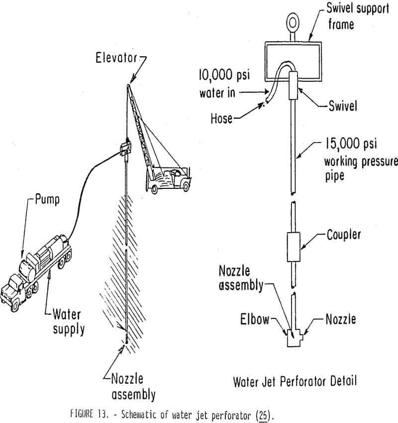
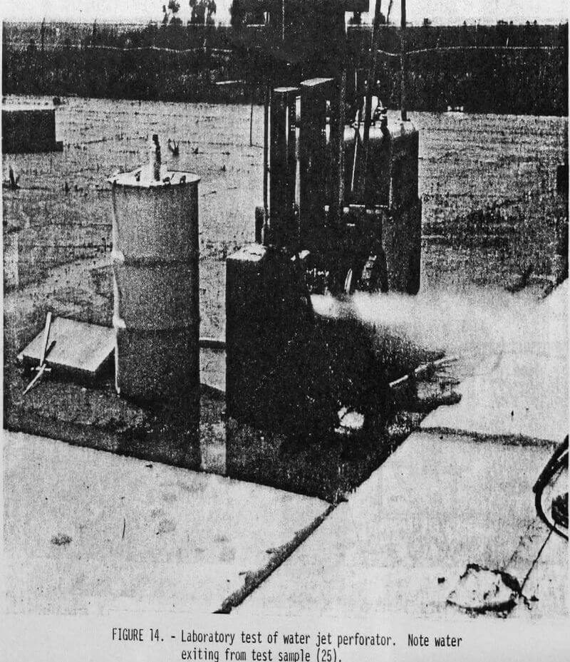
The Bureau’s water jet perforator consists of a pump, a high-pressure hose, a swivel, a string of high-pressure pipe, and a nozzle assembly (fig. 13). The nozzle assembly changes the flow direction from vertical down the length of the pipe to horizontal at the nozzle exit and converts the pressure energy of the water into kinetic energy, thereby creating a high-velocity jet which cuts the casing. Figure 14 shows the jet as it exits from a laboratory test sample.
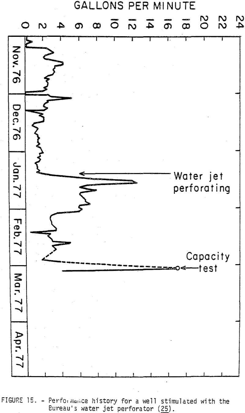
In addition to the ability to provide sand control without the placement of well screens, the Bureau’s field experiments at Wyoming Mineral’s Lamprecht site (Ray Point) and Mobil Oil Co.’s Longoria site (Bruni) in Texas identified the following potential advantages of the water jet perforator. First, the technique could be used to increase the ability to inject leach solutions through uranium leaching injection wells, which exhibit subpar injectivity and do not respond to conventional well stimulation methods, such as the use of acids. Figure 15 shows the performance history of such a well stimulated with the water jet perforator. Secondly, the water jet perforator can enhance the permeability of the uraniferous sand in the vicinity of the well bore (an annulus 1 foot [0.3 m] thick throughout the length of the mineralized zone) by selective removal of clay particles in the mineralized zone if the formation is not excessively hard. Other permeability enhancement applications might involve use of jets with higher flow rates, say up to 30 gallons (114 liters) per minute, to erode the parts of the formation wall that were damaged (plugged) by well drilling fluid during development. Finally, the jet perforator can be used to regulate the flow pattern through the mineralized zone between injection and recovery wells by the placement of a predetermined configuration of holes in the recovery wells.
Recent field experiments at Wyoming Mineral’s Irigaray site near Buffalo, Wyo., identified some additional features of the jet perforator such as the ability to operate in 2-inch (5.1-cm) diameter wells, and the ability to tolerate horizontal deviations up to 17 feet in 300 feet (5.2 m in 91.5 m) of vertical distance. The work also identified some problems related to the very competent sandstone ore. In this area sand control is not a problem, and low injectivlty is the prime concern. Jet perforator operating parameters that were successfully used in Texas did not produce satisfactory results, and further research should be conducted to evaluate higher flow rate jets in slotting configurations that might achieve the high production rates (30 gallons per minute) desired. In addition, the use of the higher flow rate jets (about 30 gallons per minute) to erode parts of the formation damaged by well drilling fluid should be extensively evaluated.
Leaching Methodology
Geochemical Modeling
Most of the preliminary data for the geochemical modeling were obtained from IEC’s Pawnee site. The ultimate goal is to develop a model that will aid in selecting the best leaching solution and concentration, oxidizer concentration, and flow rate for a given deposit, using as input the analyses of cores and ground water. The benefits to be gained from this optimization include a higher percentage recovery of uranium and possibly lower total costs for the operation. The capability for eventual computer simulation of the geochemical reactions is being developed in cooperation with the U. S. Geological Survey, Menlo Park, Calif., and Hydroscience, Inc., Westwood, N.J. Arrangements are being made to gather more field data for this task from a site in Wyoming where an acid leaching solution will be used.
Development of Computer Models for Fluid Flow
A brief summary of the first phase of the Bureau’s work on fluid flow modeling was given at the Vail Conference on In Situ Uranium Leaching. The initial product is a computer program, 5-SISL (five-spot in situ leaching), which can be used to simulate the hydrology of a single five-spot well pattern that is used to leach uranium from an underground aquifer (sandstone layer). The program consists of a number of subprograms that provide various options depending on the nature of the aquifer as inferred from core information together with laboratory and field measurements of permeability. The Bureau plans on publishing a detailed description of this program in a report of investigation.
The ultimate goal of this part of the Bureau’s model development work is to predict flow characteristics and concentration of uranium and leaching solution for a multiple-well field configuration.
Parties interested in obtaining copies of the program listings developed to date should contact the Twin Cities Mining Research Center.
Environmental Considerations
Much of the Bureau’s work in the early cooperative field experiments with industry has involved environmental monitoring of ground water quality before, during, and after leaching. Because the Bureau is not a regulatory agency, the environmental data were taken to assist the operator and the Bureau research program, not to police the site operation.
Careful preleach monitoring identified one significant fact: large variations in the ion content may be observed in a monitor well even when no leaching has been started. Variations in monitor wells during leaching may thus be due to natural variations, to changes in ground water that moves toward the leach area as more is pumped out than is pumped in, or to actual escape of leaching solution. To assist in identifying the cause of later variations, environmental data should be taken periodically at least several months prior to leaching to determine the extent of natural variations. The range of natural variation should then be considered when developing a monitoring program.
As part of the geochemical work at IEC’s Pawnee site, the Bureau took samples once or twice a day from observation wells located between injection and production wells during the initial phase of leaching with an alkaline carbonate solution. Although this sampling was done to help develop a model of the geochemical processes involved in the production leaching operation, some of the measurements had implications for environmental monitoring. The chemical front which advanced through the deposit during injection had a leading edge of bicarbonate. At an observation well only 40 feet from the injection point, the bicarbonate content rose 3 days before the content of the other ionic species. This suggests that the best “early warning device” for detecting the excursion of a carbonate or bicarbonate leaching solution to a monitor well is a bicarbonate measurement.
As part of Bureau of Mines contract J0265022, Toups Corp., is evaluating the environmental impact of in situ uranium leaching and reviewing present State and Federal laws related to application of this new mining method. The Bureau plans to disseminate the results of this research through the Contractor’s final report, which should be available early in 1978.
Further work on evaluating cost effectiveness of different techniques for restoration of ground water also is being conducted under contract.
Borehole Mining
Although the Bureau had not been engaged in hydraulic borehole mining research prior to FY 1974, it had been actively engaged in research to utilize hydraulic jet cutting technology for safer, more efficient mining of coal and other minerals and as a means of accelerating tunneling speeds in hard rock. The background gained in these investigations was quite valuable in starting research in this new mining method, which involves using a hydraulic jet to break and slurrify a deposit so the material can be pumped to the surface and processed.
Previous Industry Research
As part of the Bureau’s initial work in jet cutting in a borehole, Savanick reviewed past development and testing done by industry in borehole mining and jet cutting- in other industrial applications. Three principal patents related to the remote extraction of mineral commodities through boreholes were discovered. One patent using hydraulic jets for underreaming wells was also evaluated. Field applications of the borehole technique evaluated included the initial U.S. test conducted in 1961 by the American Gilsonite Co., at Bonanza, Utah, and the hydraulic borehole coal mining conducted by Coleman Collieries Ltd., at the Vicary Creek mine near Coleman, Alberta.
Because the past work in borehole mining had concentrated heavily on equipment development, the Bureau initiated its work in this field with a systematic investigation of the jet parameters that affect cutting and operational economics in the borehole application.
Bureau of Mines Research in Borehole Mining of Coal
The Bureau’s research in hydraulic borehole mining of coal is conducted under Advanced Mining Systems, a subprogram of the Advanced Coal Mining Technology (ACMT) program, which is also coordinated by the Twin Cities Mining Research Center (Kelly Strebig, subprogram coordinator). In addition to the several projects related to improving technology for borehole mining of coal, the Advanced Mining Systems subprogram includes research projects in high-volume hydraulic coal mining, longwall-auger mining, improved underground augering techniques, and innovative systems for longwall support and cutting functions such as the Kloswall mining system.
Laboratory-Scale Evaluation of Operating Parameters
To develop specifications for a prototype hydraulic borehole mining device, the Bureau conducted four different types of force measurement and sample breakage experiments with a model borehole device. This initial project was funded under the FY 74 Coal Mine Health and Safety program. Nozzle diameters used in the experiments were 0.107 in (0.27 cm) for the dual nozzle tests and 0.142 in (0.36 cm) for the stationary jets. Nozzle pressures ranged from 1,000 to 4,000 psi (6.89 x 10 6 N/m² to 27.6 x 10 5 N/m²). Coal and composite concrete-straw samples were used to simulate coal in the breakage tests.
Although the model device was not sufficiently powerful to mine coal economically, the jets, when operated at 4,000 psi (27.6 x 10 6 N/m²) and a 40-gpm (152-liter-per~minute) flow rate,, fragmented coal at a standoff distance of 8 ft (2.44 m). These tests showed that follow-on work should emphasize larger nozzles having much higher hydraulic horsepower. The target standoff distance established for a practical hydraulic jet borehole coal mining device was tentatively established in the 40- to 60-ft (12.2- to 18.3~m) range, and efforts to develop a tool having this level of cutting capability, coupled with improved slurry pumping, were initiated.
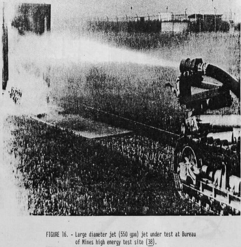
The principal conclusion of the Bureau’s follow-on in-house work on large-diameter jets (1.20-in [3.05-cm]) conducted in FY 75 under the ACMT program (fig. 16) was that these jets retained a greater proportion of their impact force at standoff distances greater than 100 nozzle diameters than did comparable smaller diameter (0.142-in [0.36-cm]) jets. This finding is of particular significance to the economic application of the borehole jetting concept. The best nozzle among the designs tested used a conical angle of 13° to produce consistently higher impact forces. The Bureau also determined that the optimum straight-section length of the nozzles for increasing the impact force is a function of the standoff distance. At standoff distances of less than 6 ft (1.83 m), a conical nozzle with no straight section produced higher impact forces, while at standoff distances between 6 and 12 ft (1.83 and 3.66 m), nozzles with a straight section three times the length of the nozzle orifice (3D) gave higher forces.
The FY 76 project on nozzle testing and slurry pumping concluded the first phase of the Bureau’s work on development of specifications for a practical borehole mining tool for coal. These investigations demonstrated that although the polymeric additives enhanced the jet impact forces, the benefits to be gained were small compared with those achievable with improved nozzle designs for optimizing the jet action at large standoff distances. Because of their inherently good reliability, jet pumps were judged to be the best choice for further development of the borehole mining concept, providing their low efficiencies in lifting slurried coal could be tolerated.
Equipment Development and Field Testing
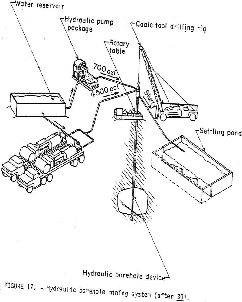
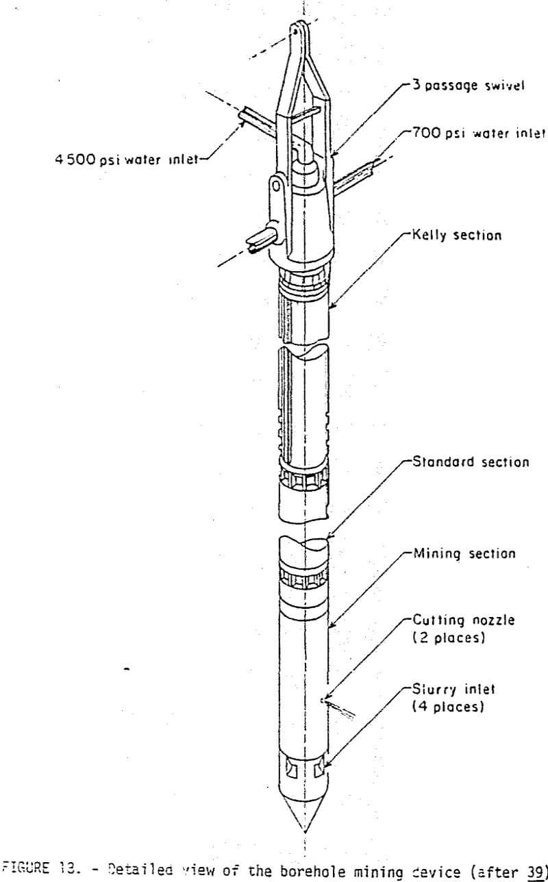
Using specifications developed in the FY 74 in-house project, the Bureau issued an RFP (request for proposal) to design, fabricate, and field test a hydraulic borehole mining tool capable of mining coal at a depth of about 100 ft (30.5 m). The successful proposer was Plow Industries (formerly Flow Research, Inc.,) Kent, Wash., which fabricated a prototype borehole device consisting of three separate systems—a hydraulic jetting system to cut the coal, a jet pumping system to propel the slurry to the surface, and a tricone bit to reduce oversize lumps of coal. The entire system would also include ancillary equipment such as a rotary table to rotate and oscillate the device, a drill rig to raise and lower the device, water supplies, and a slurry pond (fig. 17). The borehole mining device consists of three principal sections: Kelly, standard, and mining (fig. 18).
At a field test held July 20, 1976, near Wilkeson, Wash., Flow Industries demonstrated that the prototype tool could mine coal at the rate of 10 tons per hour (9,070 kg/hr) and maintain this rate of production for 4 hours. The reliability demonstrated in this initial field test was also judged to be satisfactory because the tool was operated continuously for 6 hours without mechanical breakdown or blockage occurring in the slurry pumping system.
The field test did identify a blockage problem which could constitute a potential obstacle to economic viability of the concept. This problem is caused partly by large chunks of rock and coal and partly by acicular particles which enter the pump only if their longitudinal axis is perpendicular to the inlet screen. Once inside, these particles wedge between the nozzle and the interior sidewall of the pump and cause clogging that is not correctable by back- flushing. Flow Industries, under extension of their contract H0252007, is developing an improved downhole crusher to solve the clogging problem.
The Flow Industries prototype tool is also being evaluated under AMNMT funding for mining shallow uranium deposits and is discussed in a following section. Further development of this concept to test a full-scale hydraulic borehole coal mining system is planned under the Advanced Mining Systems subprogram and will most likely be accomplished through the formal request for proposal route.
Improved Nozzle Designs for Borehole Mining
Theoretical Analysis
Under the Bureau of Mines Contract J0255024, TRW (Redondo Beach, Calif.,) used a computer model of the free jet to predict the decay of the jet center line stagnation pressure and axial thrust as a function of distance for different nozzle flow channels and pre-nozzle flow straighteners. The goal of the research is to develop nozzle and straightener designs that will produce high-impact forces at large standoff distances, yet be sufficiently compact to fit in the confined geometry of the borehole tool. The approach taken in the theoretical design development was to minimize initial disturbances, such as turbulent eddies or cavitation bubbles, to delay the ultimate jet breakup.
Several nozzle designs for different flow conditions were recommended for experimental testing. Although the overall effect on the design was to shorten the length and accept larger converging angles, cavitation and separation problems were present to complicate the analysis under different flow conditions.
Testing Improved Nozzles
TRW’s computer predictions indicated that flow splitters placed in a 90° elbow would be the optimum flow-straightening device. To be effective, however, the splitters had to have the following characteristics: (1) High radius ratio (mean radius/diameter) for minimum separation, (2) high aspect ratio (width of vane/distance between vanes) for minimum secondary flow, and (3) equal radius ratios for uniform velocity. TRW’s experimental program includes testing the flow straighteners with different nozzle configurations. Tests will be conducted on three turn devices, one without flow splitters and two with splitters. Forces will be measured at 10-ft (3.05-m) intervals from 10 to 50 ft (3.05 to 15-2 m).
The Bureau’s in-house work (FY 77) in nozzle evaluation is coordinated with the experimentation being conducted at TRW. To date, the Bureau’s tests have indicated that a large quartic-straight (Q-S) nozzle (160 psi, 250 gpm [1.10 x 10⁶ N/m², 950 liters per minute]) performed as well as the standard 13°-3D nozzle with a 58-percent saving in nozzle length. The results of these investigations will be used to design improved borehole mining tools capable of cutting material at greater standoff distances.
Bureau of Mines Research In Borehole Mining of Uranium
The Bureau is not alone in evaluating borehole mining techniques for exploiting mineral deposits. Continental Oil Co., and FMC have both evaluated the technique for mining phosphate deposits. Marconaflo has tested its borehole mining method in remining or moving tailings as well as direct extraction of uranium deposits. Tests by Marconaflo have confirmed that borehole mining of uranium and oil-saturated sands with its tool was technically feasible. Deficiencies in the Moyno slurry pump, however, convinced Marconaflo that a different pumping system is required and further R&D should be conducted. One particular item of interest in the Marconaflo report is the concept of using leaching solutions instead of water to slurrify the ore and.the contention that this might be an effective means of site benefication.
The objective of this part of the Bureau’s in situ mining sub-program is to evaluate the design changes required to make the prototype borehole mining tool developed by Flow Industries under contract H0252007 an economic mining method for mineral commodities. Because of its high unit value and importance in the overall energy mix for the Nation, uranium was selected as the first commodity to investigate. To date, evaluation has proceeded under four principal areas (fig. 3): SOA review, slurry pumping tests, field testing of the prototype, and evaluation of the environmental factors affecting widespread application of this new technology by the mining industry. Because the initial equipment development has been done under the Advancing Coal Mining Technology program, improvements in the technology would also be made under ACMT auspices unless the field demonstration (funded in FY 77) would show that improvements of a nature specific to uranium mining would be required. These advances would be made under AMNMT funding.
Laboratory-Scale Evaluation of Operating Parameters
The technical and feasibility investigations on borehole mining of minerals conducted by the Bureau in FY 76 indicated that the best commodity targets for this technology were deposits similar to the phosphate deposits of North Carolina and uranium-bearing sandstones, particularly the poorly cemented sands of Texas and certain areas of Wyoming. Laboratory cutting tests on selected samples demonstrated that adequate production could be achieved by low-pressure (500- to 2,000-psi [3.44 x 10 6 N/m² to 13.8.N/m²]), high-volume (300- to 1,000-gpm [1,135- to 3,790-liter-per-minute]) water Jets. The results of the assessment of the pumping technology required for borehole mining of minerals were similar to those of the evaluation conducted for coal. The best pumping system for reliability was the jet pump. Laboratory tests using a quarter-scale model jet pump proved that slurries of phosphate and sand could be raised up to 200 ft (61 m). Although single-stage jet pumps are capable of hoisting such material to heights of 500 ft (152 m), the efficiency of, the pumping system falls from the 40-percent level achievable at a height of 100 ft (30.5 m) to 10 percent at the 500-ft (152-m) height.
Field Testing of Prototype Borehole Mining Tool
During the first phase of field testing the prototype borehole mining tool (June 13-July 16) Flow Industries mined 100 tons of uraniferous sand from the Teapot sandstone ore body at Rocky Mountain Energy’s Nine-Mile Lake site near Casper, Wyo. The formal public demonstration also conducted under contract H0272010, confirmed that the tool was capable of mining at the rate of 11 tons per hour at a depth of 100 ft. This device or a higher horsepower unit capable of increased production has significant potential for exploiting shallow deposits. Critical factors such as reliability, maximum radius of cutting, and cavern stability are targets for evaluation in follow-on work. Results of the Bureau’s evaluations of the borehole mining tool in uranium deposits will be disseminated through the usual publication channels including the Contractor’s final report.
Summary
This paper has described the in situ mining research conducted by the Bureau and coordinated at the Twin Cities Mining Research Center (TCMRC). Specific accomplishments have been covered under the individual project summaries. Additional details on completed projects are available in the publications cited. Because much of the research summarized represents interim progress, parties interested in obtaining updated status or recent publications should contact the author at TCMRC (612-725-4540). The Bureau also desires to obtain feedback from the mining industry to assist in directing its in situ mining research toward removing the critical obstacles precluding widespread use of these new mining technologies.