Table of Contents
The first motors of this type were built to drive ball mills in the cement industry, which are very similar to those employed for ore processing. Here, too, the tendency is to build units of ever increasing capacity. In the case of conventional drives with mechanical gearing, this involves correspondingly increasing difficulties.
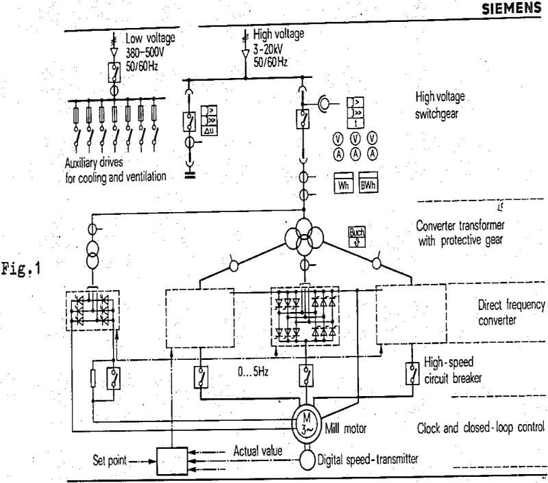
Technical principle
A high-voltage supply is taken to a special type of transformer with three secondary three-phase systems. This transformer may be replaced by three separate three-phase units..The phase-angle-controlled converter cuts out one phase of the low-frequency three-phase supply from each of the three three-phase currents available from the transformer secondary. This frequency can be varied between 0 and about 50% of the system frequency, the latter value being the maximum for which the cyclo-converter can be designed. The low-frequency output of the converter is supplied to the stator circuit of a synchronous motor through special circuit-breakers. The thyristor gate control is activated by a digital speed transmitter, which ensures that the motor and converter are always in synchronism, i.e. the motor is safely prevented from falling out of step. The motor field circuit is supplied by a separate transformer with a controlled rectifier in the secondary circuit. Since it is not possible to supply reactive power back to the system economically, capacitors are employed for power-factor correction.
Mechanical coupling problems
In the case of the gearless drives so far installed in cement factories, the mill and motor were in most cases combined to form a unit. With most of these installations, the motor is “wrapped around” the mill, a method which affords the following advantages:
- The overall length of the installation, and thus the building costs are reduced
- The motor does not require any bearings, the rotor thus becomes cheaper, and a coupling is eliminated
- The mill remains freely accessible at both ends.
The manufacturing and assembly tolerances of the mill and motor must, of course, be co-ordinated carefully to ensure that the eccentricity occurring will not unduly interfere with the air gap of the synchronous machine. Thermal expansion and static and dynamic deflection must also remain within the permissible limits. Experience acquired so far indicates, however, that all these requirements can be met without great difficulty.
The 6800 HP mill drive at Rohrdorf, West-Germany
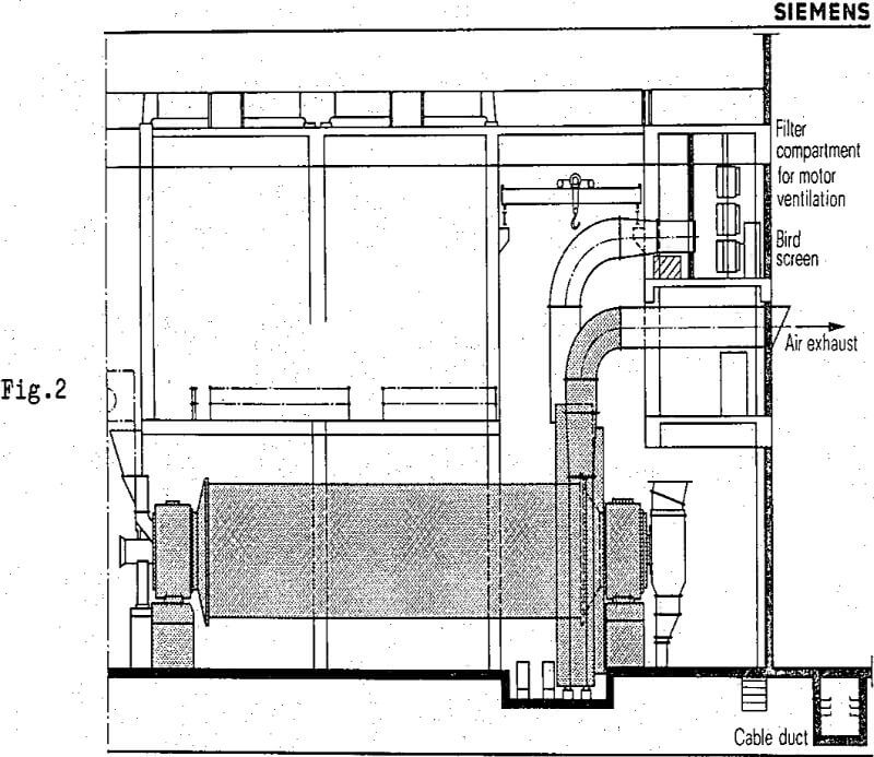
In February 1972, a 5 MW drive wrapped around a cement mill with a capacity of 160 t/h was commissioned in the cement factory at Rohrdorf. Up to now, the mill has been operating without an interruption. The mill is of the two-compartment type, is 16.5 m long and has a diameter of 4.6 metres. The drive was designed for a speed of 14.6 r.p.m. The reasons prompting the use of a gearless drive were the limited space available, and the difficulties experienced in that factory with large gear units.
The motor is a synchronous machine with 40 poles, designed for a service voltage of 1500 V. Its output is 5000 kW at 14.6 r.p.m. The motor is ventilated by a separately installed fan which draws in the air through a filter. The hot air is exhausted to atmosphere. Thus a very simple method of ventilation has been adopted.