Pinson Mining Company was formed to develop a gold orebody located in northern Nevada near Winnemucca. A feasibility study was undertaken in 1979 by a consortium of three Toronto-based mining companies arid a Reno-based exploration company.
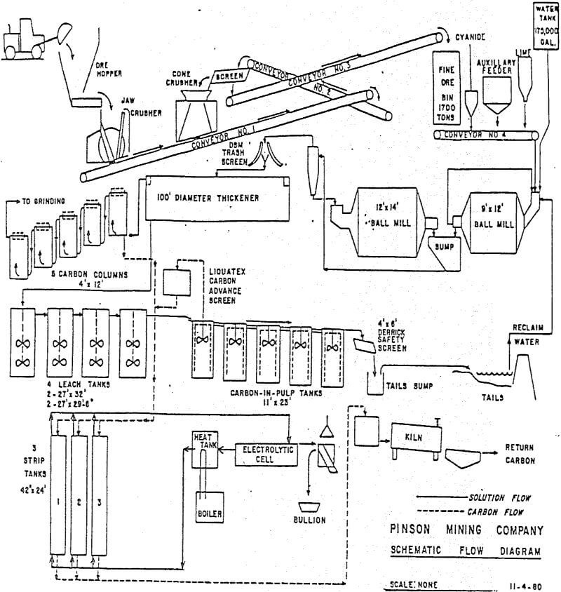
The Pinson plant has been described in some detail by Mcquiston and Shoemaker in the AIME’s Gold and Silver Cyanidation Plant Practices. I will review the flowsheet only briefly, highlighting significant features. The emphasis of this presentation will be on specifics of the design.
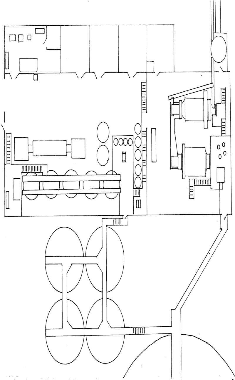
The crushing plant flowsheet is illustrated. It is a conventional two-stage plant, producing a minus 5/8 inch product. The most significant feature of the design, from a mill superintendent’s view¬point, was the provision of a belt plow and outdoor crushed-ore stockpile. This stockpile of about 20,000 tons is used to maintain steady mill feed during crushing plant maintenance shutdowns.
The grinding circuit is illustrated schematically also. The Pinson ore is extremely clean from a leaching standpoint. There are no sulfides or carbonaceous materials to consume reagents or rob dissolved gold. This fact allows the leaching reagents to be fed dry onto the mill feed belt with the crushed ore, eliminating the capital and operating cost of a reagent mix system.
Cyanide leaching is rapid in the grinding circuit. Following the six hours retention in the thickener, about 80% of the gold is in solution.
The pulp then flows by gravity to a five-stage carbon-in- pulp circuit. The CIP tanks are unique in North America. They contain Lightnin-designed draft tube agitators and were selected for their low horsepower requirements. They provide very gentle agitation which nevertheless is adequate for suspending the slurry particles. In the carbon-in-pulp circuit, we sought to minimize power input in order to minimize carbon attrition. Although carbon fines lost to attrition have a small replacement cost, such carbon fines carry absorbed gold to tails with them, and are therefore of great concern.
Loaded carbon is stripped in 3 ton batches using 1.5% caustic and 0.15% cyanide at 195°F under ambient pressure. At completion, after approximately 72 hours, the carbon has been stripped to 5 ounces per ton.
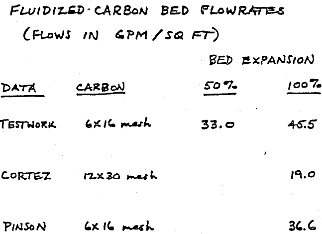
Empirical data is now available from Pinson also, indicating the maximum throughput rate manageable to be 460 gpm, or 36.6 gpm per square foot. Obviously, the bench testwork can provide a useful design guide, but must be interpreted with some caution. It is apparent that the carbon size must be selected and accurately known before columns can be designed.
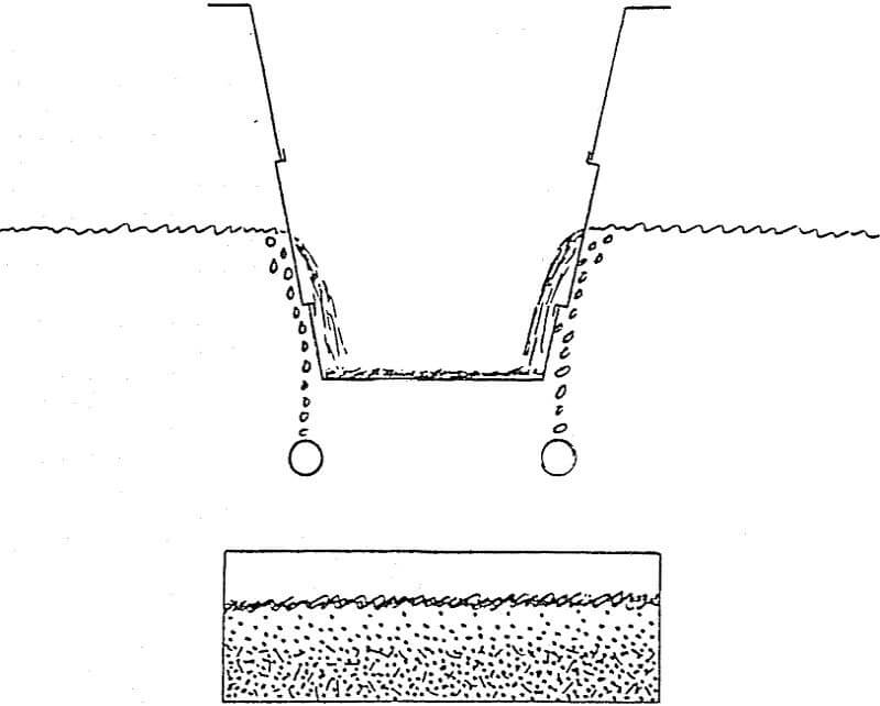
It appeared that the critical parameter was not square feet of screen area, but rather linear feet of screen, measured parallel to the pulp surface. Observations of the system at Pinson have since confirmed this, although we had some misgivings about it in the design phase. The rational is illustrated in this sketch.
On average, only about ¾ inch of the screen’s height is active. The upper portion is obviously not in use, being above the pulp level. The lower portion is blinded off, with carbon particles primarily, but also with wood chips, truck tire bits, and lime scale. The air bubblers continually sweep this build-up, however near-size particles gradually blind off the screen from the bottom up.
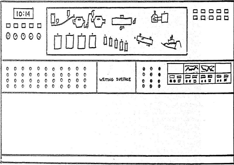
The front of the control panel is illustrated here. The graphic displays the entire flowsheet. Green lights indicate operating equipment motors. When an alarm sounds, a red light will flash on the graphic identifying the source of the trouble. The operator pushes the acknowledge button to silence the alarm horn, and the red light changes from flashing to steady red. The red light will stay on until the problem has been corrected.
Unlike the crushing plant, the milling circuit was very cost-sensitive to tonnage rate. In view of prevailing 21% interest financing rates for the project, our guidelines were very clear to construct only for the proven ten years reserves. However, without adding to initial capital cost, provisions were made in the design layout and equipment selection stages for future tonnage increases to 2000 tons per day. Additional equipment expenditures would be needed of course, but the plant layout would permit installation of this equipment with little disruption of ongoing production.