
Table of Contents
More than ever, public opinion is demanding the design of stable embankments as part of tailings disposal systems to aid in abating air and water pollution. Even though many areas have no restrictions requiring industry to impound its tailings, great interest has been generated through universities, industry, and Government in developing sound engineering principles regarding disposal problems. In some areas, attempts are already being made to prevent mine operations from starting because of the probable damage to local esthetic values. Because abandoned disposal areas are the land owner’s liability when the mine has been exhausted, and must be a paramount consideration of planning groups that look 50 years hence at land disposition requirements, disposal costs and methods have become a significant mine operations problem.
The Bureau of Mines initiated a project concerned with the design of a tailings disposal system through its Heavy Metals Program. The information gathered, which includes the best methods for construction of a stable structure, maintenance of water conservation, control of air and water pollution, and provision of adequate land reclamation, applies generally to the disposal of all conventional mill tailings. The solutions offered here are based on theoretical and technical data from field studies made throughout the United States and on the application of various soil mechanics techniques.
Over 30 mines were visited, and studies were made of recent advances in soil mechanics methods and applications. Some of the practices are currently part of the waste disposal technique for one or more of the mines visited.
Others are modifications of current soils engineering practices. While these construction principles can be applied to all types of mill tailings dams, each area, climate, and subsequent use requires some modification in the various design parameters. Due consideration to the various parameters will result in a stable, functional disposal system, constructed and maintained at reasonable cost.
Pre-construction Engineering
With any type of major dam construction a complete hydrology study, including a determination of the amounts of milling, domestic, and excess water, must be made for design purposes. Often this information is available at no cost from State and Federal water resource agencies. The design of the dam must allow for the total natural and artificial runoff, so that when the area is abandoned the water can pass through or around the dam without soil erosion or undesirable impoundment occurring. Any decant or bypass system required to move the water through or around the abandoned tailing dam should be designed so that maintenance cost is negligible. In this way the disposal system does not become a liability to either the mining company or the public.
Foundation investigation, the next critical area of study, can be accomplished through selective drill-hole soil sampling and testing. From this information, the geologic structure of the substrata can be predicted as well as basic foundation data (permeability, density, and shear strength values).
In many cases, when the structure is failing, these substrata design values are needed before effective rectification can be made. Such information is inexpensive to obtain and worth the money expended, since it is applicable both to embankment stability and to the design of decant lines that are to be constructed in the base. Numerous failures that resulted simply because soil conditions under the original structure were not investigated, have led to liability suits. One reported failure caused an estimated loss of between $13 and $14 million from claims and damages, owing to either a lack of engineering or, more probably, the failure to follow the engineering design as specified. On the other hand, proper engineering can eliminate costly overdesign and superfluous safety factors.
Soil Sampling & Testing for Design Parameters
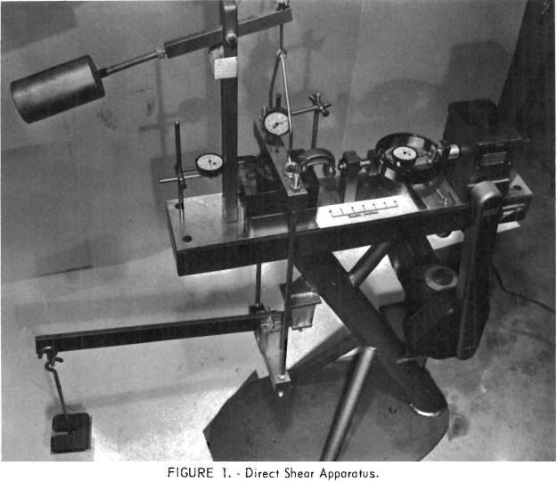
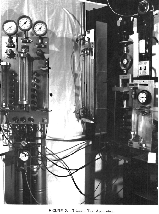
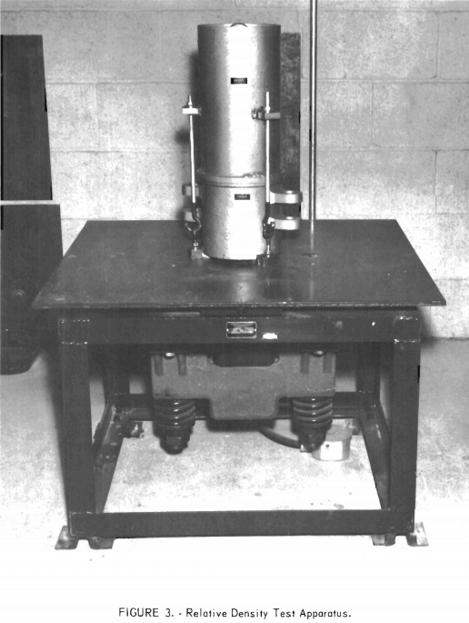
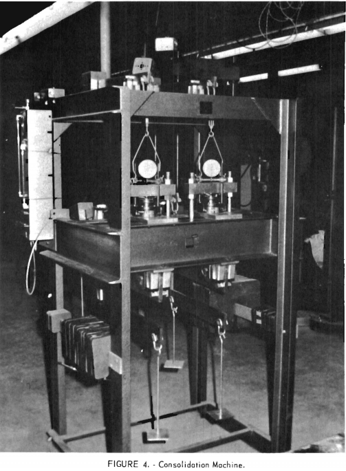
When developing design data for embankment stability, the existing tailings structure as well as any tailings structure yet to be constructed must be considered. The data needed to determine the factor of safety that an existing structure has or will have with further deposition of tailings is obtained from in-place samples. These readily available undisturbed samples can be obtained with numerous soil sampling tools. It is distinctly advantageous to develop such data while the representative samples are available. After the sample has been extracted it is tested in the laboratory for the required design parameters, which are relative density, moisture, shear strength, consolidation, and permeability. Figures 1 through 4 show the laboratory apparatus.
Access to an existing structure is also essential to the applicability of in-situ testing. Radioactive probes are being used to obtain density and moisture values in the field. Although in-situ vane shear testing has also been tried, such values have not been completely satisfactory. The standard penetrating test using the split-spoon samples has been used for comparing values and provides good guidelines simply because of the large volume of penetration data available. Necessary field measurements of the phreatic water-line and the general geometry of existing slopes are easily obtained for use in basic stability calculations.
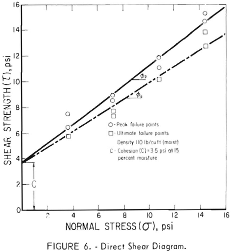
A combination of experience with existing ponds of the same type and/or simulated undisturbed sample testing of the tailings to be impounded can also provide values for the necessary design parameters. Typical void ratios and possible shear strength of emplaced tailings can be approximated in a simple laboratory model, such as that shown in figure 5, in which the tailings are

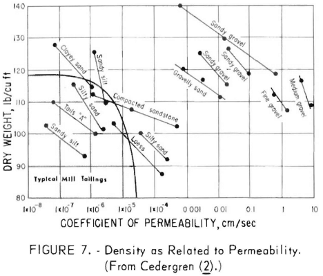
poured at the slurry density expected to be used in the proposed pond. Samples are extracted and subjected to standard tests. Consolidation tests performed on the extracted samples can approximate what will happen to the soil as the height of the pond increases, thus changing the three most critical design parameters, density, shear strength, and permeability. Figure 6 is the shear diagram developed in our laboratory for one particular soil. As indicated by the shear diagram, two phi angles (∅) are developed from the direct shear test. It is probably more realistic to use the ultimate phi angle for stability calculations, discounting some intergranular friction. Reasonably good stability predictions can be obtained by using these phi values in a slope stability analysis. Figure 7 shows the effect of density and grain structure on the coefficient of permeability.
Basic Design Methods
Two basic techniques for constructing tailings dams will be covered in this report (1) the use of mill tailings themselves as the construction medium and (2) the use of borrow material to construct the retaining structure and impound the tailings.
There are three basic construction methods: (1) the upstream method, (2) the downstream method, and (3) dams from borrow material. Each of these methods has its function depending on locality, climate type of operation, etc.
Upstream Method Design Techniques
One of the biggest problems observed on visitations throughout the United States is that the initial starter dike, which is typically used in upstream disposal systems, is frequently constructed of clay, on the assumption that this is best for the pond. A clay dike, however, which has a water-retaining ability
and critical location, will hold water that promotes instability by reducing the cohesive strength and raising the phreatic line.
Considerable effort should be made to see that the starter dike is built on a strong base having a scarified
surface free of all organic matter. The dike can be constructed of coarse rock, gravel with sand mixture, or any pervious material as long as the upstream side has a gradation into sand to prevent the piping of
tailings through the rock. This starter dike, which ultimately becomes the toe of an immense structure, should be as structurally sound as the footing under a building.
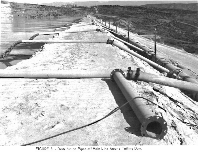
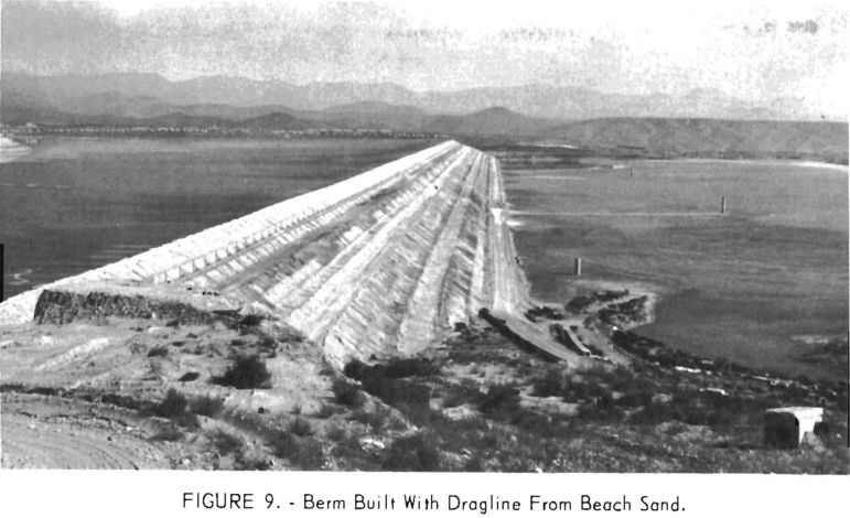
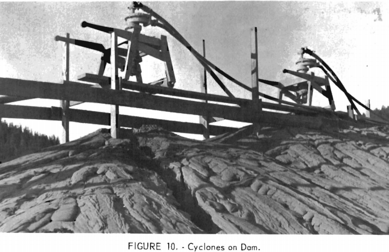
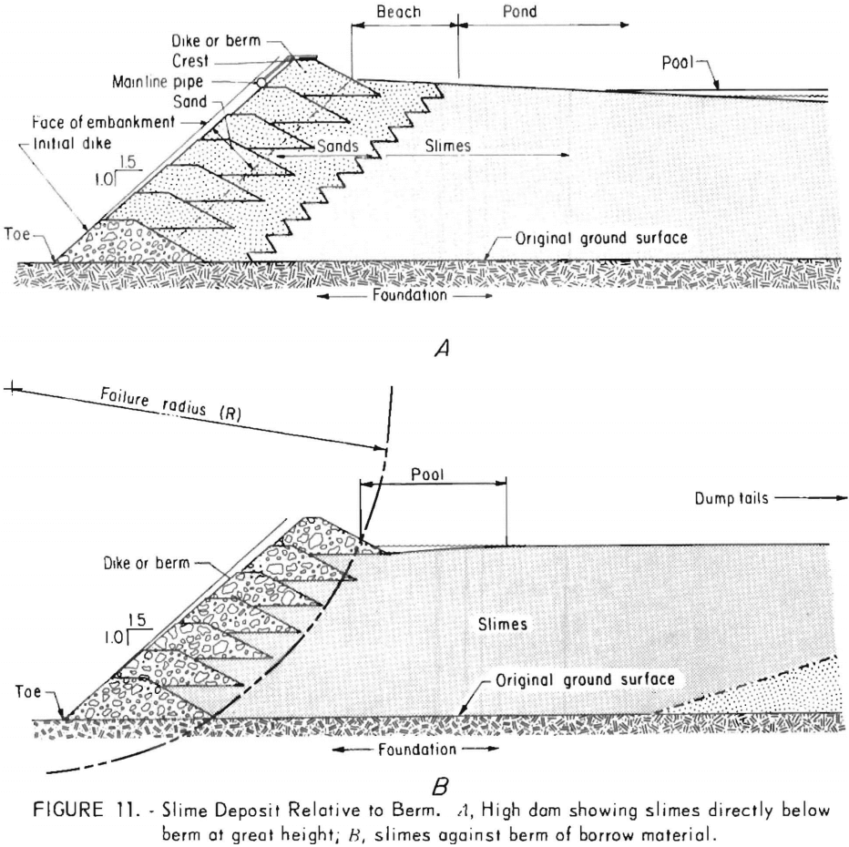
The most common upstream method, and probably the cheapest and best, is to place the main line around the periphery of the dikes. The line should discharge into the pond every 10 to 50 feet, depending on the size of the installation. Bleed lines, which range in size from 2 to 6 inches, can be used to build up the dike to heights of 20 to 30 feet in 8- to 15-foot increments before the main line must be moved (figs. 8-9). If the density of the discharge is low enough and there is a relatively large size differential between the coarse and fine fraction, a beach of considerable size is the result. Cyclones, if necessary, serve a useful purpose because they (1) keep the coarse material, which is excellent for berm building, at the outside and (2) can discharge the slime fraction far into the pond if desired (fig. 10). Figure 11 shows effective and ineffective relationships of slime deposit to the berm. In large ponds having a wide beach (200 to 300 feet), as the upper panel shows, the dams can be built to a much greater height, with even a 1½ to 1 or a 2 to 1 slope, before any previously deposited slimes lie directly below the newly placed berm.
Probably the most unsafe practice, on the other hand, is to discharge the tailings so that the slimes and water lie against the dike. With this method there will be slimes from bottom to top, as the lower panel shows, held by a relatively thin shell of berm, generally of borrow material. This slime material has a high void ratio, retains vast amounts of water, and has a low bulk density, low phi angle, and consequently lower shear strength than does a sandy material. The phreatic surface (upper limit of water saturation) is high in the dike on both the upstream and downstream sides. Consolidation of the material takes place slowly because of the necessarily slow buildup in the dam’s height. Because the horizontal and vertical permeability is very low, water is squeezed out slowly and it takes longer for the slime material to attain any shear strength. The material for some distance back from the berm and for a considerable depth is saturated, has no cohesion and no shear strength, and is held in place by the berm only. The berm itself becomes saturated, reducing the safety factor still further. In general, it is good to pool the water against the uphill side of the area as far away from the periphery of the dike as possible.
When building the berm, whether by dozer or dragline, an effort should be made to obtain compaction either by dynamically dropping the sand load or by running over it a few times with a dozer. As described very well by Hough, compaction of a soil produces a tremendous increase in shear strength. The berm should have both good compaction and high permeability in order to transmit a free flow of water to the outside, while being sufficiently compact that, if it is saturated, a sudden load or seismic shock will not cause liquefaction. When liquefaction does occur, the berm loses all shear strength, the water takes the load, and failure is instantaneous. The beneficial effect on stability by compaction of the berm outweighs the decreased permeability produced by the compaction.
Downstream Method
Some foreign mines use a type of berm building that is the reverse of common practice in this country. The coarse material discharged from cyclones around the periphery of the dike is deposited on the outside of the toe; the slimes are deposited on the inside (fig. 12), producing a very pervious, triangular dam, which is very stable and safe but requires much more labor for moving and tending the cyclones. Because the area of the dam increases as it
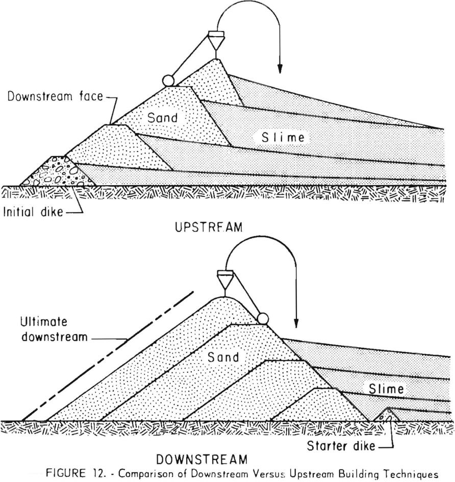
gets higher, more and more sand is required per foot of elevation rise in the dam, as can be seen by examining figure 12. This method can be safely used in building very high dams because of the bulk and density of the mass of sand; height is limited only by the volume of available sand. The downstream slope must be calculated for each operation and is governed by the shear strength, etc. Only mines not using their tailings for underground fill would have enough sand available for building dams in this manner. Even then, however, the additional cost is not normally warranted, since a very good dam can be built by previously described conventional methods.
Dams of Borrow Material
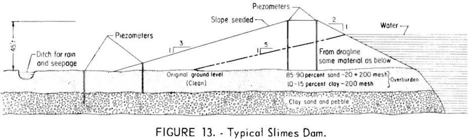
Tailings dams that do not use peripheral discharge, but simply dump the sand at the high side of the tailing area or are impounding slimes only, would normally be the only ones with berms built of borrow material. Occasionally the operators might prefer to make the berm of borrow material even though sand is available. Borrow material is very often 85 percent sand and 15 percent clay, or some mixture of gravel, sand, and clay. A decrease in the clay content from 15 to 10 percent can make a big difference in the permeability (k) of the embankment. As Cedergren has pointed out, grain shape, size, and gradation are extremely critical in determining permeability. In localities where the dams are built of from 85 to 90 percent sand and 10 to 15 percent clay, the phreatic waterline assumes a slope of 5 to 1. These dams are designed so that the line will intersect the base well within the toe of the dam (fig. 13). The location of the phreatic line is critical to slope stability. A small addition of clay can change the slope of the phreatic line to a figure as great as 6 or 7 to 1, creating instability. If the pond is filled slowly, the phreatic line in the dam can be carefully monitored with piezometers.
A high clay content in sand and gravel borrow material placed unzoned results in a homogeneous dam that is quite impervious when tightly compacted. Although a common practice in some places, this is not desirable because the waterline will be high in the dike even with a wide deposit of sand (beach) along the inside of the dam. The phreatic line will intersect the berm at the same point and emerge high on the downstream face. The outside of the dike will eventually slough and fail. Because the berm is more impervious than the material it is containing, the berm will govern the water level. A loosely compacted berm will fail very soon; a very highly compacted berm will take somewhat longer to fail. Local sloughing and piping will show on the outside of a clay berm and is a warning that failure is imminent.
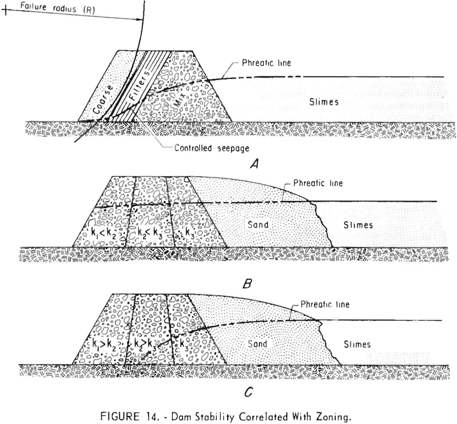
Stability can only be achieved by proper zoning. Borrow material and/or classified mill tailings can, it properly placed, produce the desired dike section as illustrated in figure 14. Figure 14A illustrates a homogeneous mix alone, which does not control the seepage water without the filter and coarse zone downstream. Figure 14B illustrates the very unstable condition provoked by improper alinement of the zone section; that is, the downstream zone permeability (k1) is more impervious than those upstream (k2 and k3). Figure 14C shows that the same material as that used in figure 14B, when properly placed, can provide excellent seepage control and consequently better stability.
Water-Dam Construction
Cyanidation mills and some iron ore plants which have contaminants that cannot be released into streams without treatment generally use the water-dam type construction. Some phosphate plants also use this type of dam to impound slimes. Water-dam construction is very costly and does not permit the free drainage of slimes for ultimate disposition. The design of these dams, which is well covered in the literature, corresponds to the purpose it is to serve and to the terrain and climatic conditions of the geographic area.
Rock-Fill Dams
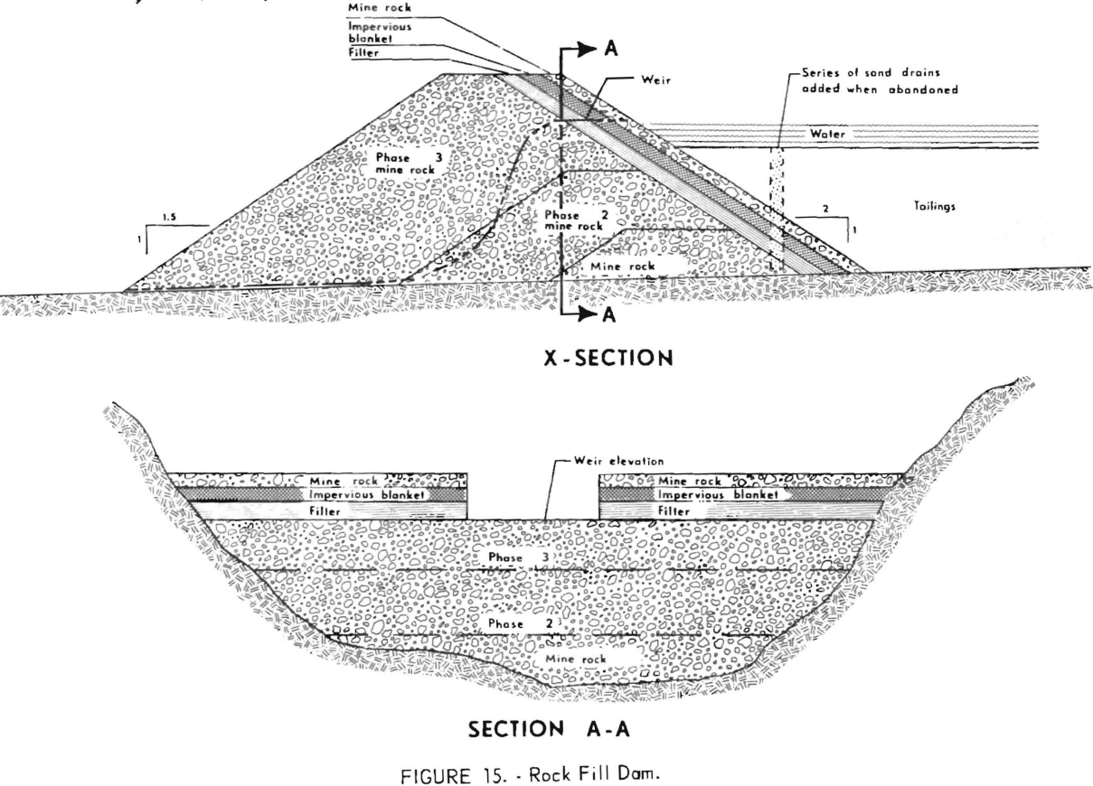
Rock-fill dam construction is a unique way of disposing of coarse mine and/or plant waste materials in the process of constructing tailings-disposal ponds (fig. 15). Such a construction method provides excellent stability and can provide a built-in spillway through the “soil weir” to guard against over-topping. The method is best used when the tailings structure must be built in a stream or river channel and provides for the passage of watershed flows through the pond. Ultimate water movement and the dewatering of the slimes can be accomplished by adding adequate drainage, for example, sand drains, when the structure is to be abandoned.
Free-Water Control
Free-water control is common to all three previously discussed building methods and is one of the most critical features in the disposal system.
Return water can be removed from the tailing pond (1) through towers and decant lines, (2) by barge pumps on the surface of the pond, and (3) through siphons off the top of the pond to permanent pump installations. With any of these systems there must be absolute control of the water in the dam, both to regulate the return water needed and to keep the water as far back from the perimeter of the dike as possible.
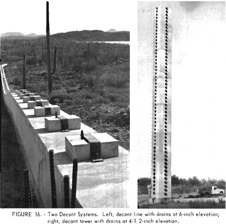
The tower and decant line system is very good where a firm base is available on which to build. In large installations they must be built to withstand the load without sinking into the base or being crushed. If practicable, it is advisable to build the lines on bedrock using heavily reinforced concrete, with water decant holes every 2 to 6 inches of elevation. The decant line through the dam should have several seep rings to prevent piping along the line and ultimate failure. The towers also must be constructed of reinforced concrete, strong enough to withstand wind as well as other loads. The decant holes must have positive and foolproof cutoff stops, for once they are under 50 feet of slime they are expensive if not impossible to repair. Figure 16 shows a large decant line and tower. In large installations, the decant lines should be built large enough that they can be entered for visual inspection.
In the smaller installations of relatively low height and short life, a solid steel pipe or reinforced concrete pipe on a firm base with several seep rings is adequate. If the pond is built against a hill, the decant line can be run ups lope and pipe can be added to regulate pond elevation as the dam height increases.
The advantages of the decant system include (1) the possibility of planning and construction well in advance of actual tailing deposition, (2) permanent pump installation (that is, no relocation is required), (3) drainage through the area after abandonment, and (4) the simplicity of operation.
The disadvantages of the decant system include (1) possible deterioration of the dam by piping, (2) difficulties of adding on to the top of decant towers, (3) increased cost of pumping water from the bottom of the pond as compared with pumping from the top, and (4) possibilities of failures or leaks occurring along tower or line.
Barge pumps and siphons are used on many dams. Besides eliminating costs for towers and lines, these methods are more advantageous than decant towers in that there are no pipes of any kind which might fail within the dam, and there is less lift of water for return to the mill.
Some of the difficulties involved with barge pipes and siphons follow:
- Raising the pumps as pond level rises, although not difficult, requires care.
- Power outage leaves no place for water to go and could cause overtopping of the dam.
- Freezing weather is a nuisance. (Compressed air or circulating water must be used to keep ice from the barge. )
- There is no way to take care of surface drainage after abandonment.
- The siphon can lose its prime with subsequent rise of water level.
- In a siphon system, the water must be against the dike unless other arrangements are made.
Slope Stability
Slope stability analysis, until recent years, has been a long and tedious calculation. Now, however, computer programs are used to calculate and select the minimum failure circle. There have been numerous programs written for the Fellenius method, the original method of slices, and the Bishop method. The Fellenius method develops a conservative estimate since it completely neglects the side forces on the individual element slices; the Bishop method is the more accurate. A study of all of these programs has resulted in the selection of the modified Bishop program, originally written at M.I.T. and slightly modified at the Bureau of Reclamation, to include both the Bishop and the Fellenius factors of safety. The Bureau agrees with R. V. Whitman and W. A. Bailey that this is the best program available today.
The factor of safety is defined as the moments about the center 0 for the circular failure are ABCD, as shown in figure 17, and is described by the equation

Where W = weight of soil and water, lb,
C = cohesion for soil, lb/sq ft,
b = width of slice,
δ = element angle,
N = effective normal force,
∅ = friction angle,
and F = safety factor.
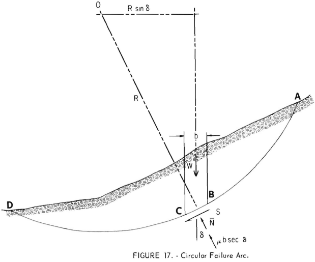
The denominator of the equation for F is an exact expression for the moment of the weight of the soil in the failure mass. (The radius R cancels since it occurs in both the numerator and denominator. ) The numerator is the moment of the shear stress about 0 along the failure surface.
N is determined for the simplified Bishop method by the sum of forces in a vertical direction, according to the equation
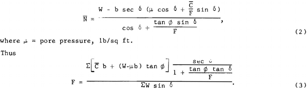
Since F appears on both sides of the equation it must be solved by successive approximations. This is the equation for which the complete program was written.
The computer will systematically search through the numerous failure circles as outlined in the guidelines of the program. It will select a minimum failure circle (the plane along which failure will normally occur) while also computing the individual circles so that the effects of the geometry, etc., can be studied in each case. At the end of the program the computer will list the minimum of all the circles selected for that particular embankment and conditions.
The simplest way to illustrate the mechanics of the computer program is to present an example. Figure 18 shows the soil properties and the location of minimum failure circles for two different conditions that were analyzed. Case 1 assumes a high phreatic line, and case 2 assumes the water table at ground level. Although the geometry and soil structures are identical for both analyses, the difference in the location of the phreatic line does alter some of the soil properties, as shown in figure 18. By comparing the computed minimum safety factors (1.14 versus 2.67) one can see that the location of the phreatic line is very critical for determining stability. A factor of safety of less than 1 is a failure situation, above 1 is a stable situation, and 1.5 is normally considered a safe design value, particularly if the soils are somewhat coarse and not likely to be subjected to seismic activity.
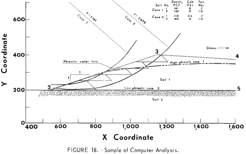
Complete computer listings of input and output for cases 1 and 2 have been included as appendixes for those who would like to study the computer searching and analyzing procedures in more detail. All of the failure circles tried are listed, and the factor of safety is computed for both the Fellenius and Bishop methods.
Should the embankment conditions indicate other than a circular arc failure, a second computer program using the Morgenstern and Price procedure can be used. With this program any desired geometric failure plane can be described and the factor of safety attained in a few minutes of computer time. Unlike the Bishop program, it does not search for the minimum safety factor but produces only the input failure plane. Since the development of computers, the most difficult part of the slope stability analysis is providing correct input data, a point that cannot be overstressed.
In most cases it is extremely difficult, if not impossible, to obtain soil samples that are truly representative of the zone being studied. Consequently, the soil properties developed from these samples must be interpreted and applied with great care. Assuming that input values developed are representative of the actual case being studied, the computer factors of safety are only general guidelines and are meaningful only if used in conjunction with all of the other design considerations.
Further Design Considerations
The engineer must anticipate and design for the worst possible condition, that is, ultimate height, maximum phreatic line, saturated soils, and seismic activity, when determining values to place in the computer program. Only then will the safety factor be meaningful.
Grain size distribution, the area of the tailing pond, and the rate of discharge have much to do with the stability of the embankment. A finer grind in the mill combined with the coarse fraction being taken out for use as underground fill has made dike building more difficult. Combine these factors with the small pond area compared with the tons of waste per day and the situation becomes worse. The tailings used underground at some properties do reduce the total that must be impounded on the surface by 40 percent or more, but they also remove the coarse sand, the best material for building the dike, and the coarse sand beach which provides added safety in front of the dike.
An example of rapid building is a situation in which a 500-ton-per-day operation has 300 tons per day impounded in a 5-acre site with a pond rise of 1 foot in 33 days or even a 10-acre site with a 1-foot rise in 66 days. Such situations could cause a rapid increase of pore pressure because the water does not have time to percolate through the fine material, especially if the dam is impervious and there is no peripheral discharge, leaving water and slimes against the dike. Even with the best of conditions, too rapid building is not good, and every effort should be made to keep the annual rise compatible with the seepage ability of the soil.
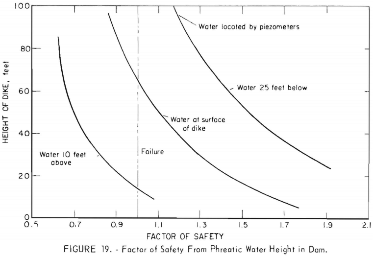
Piezometers installed in proper places in the embankment will allow monitoring of the pore-water pressure in the dam which can be related directly to the safety factor as shown in figure 19, a typical graph showing the variance of safety factor with phreatic water height in the dam. Through engineering soils mechanics, this type of chart can be developed for any dam and used by the operators as a monitoring device to predict the safety of the embankments. The phreatic surface is related to the rate that material is placed around the periphery of the dike.
If disposal areas must be small, additional areas must be provided when monitoring indicates the approach of an unstable situation. This will allow the area to decant and drain, consolidate, and lower the waterline. By alternating between two or three small areas, each one becomes more useful and will have a greater ultimate capacity. Operations in areas having extreme weather that prohibits berm building in the winter must build sufficient berm during good weather to allow dumping in large ponds during winter months.
In a seismic area safety factors cannot be accepted at face value because of the possibilities of liquefaction from either earthquake, sonic blasts, or sudden load owing to the inherent moisture and density of the material. Soils in the 80- to 280-mesh sizes, saturated, and above the critical void ratio, are very sensitive to liquefaction. Soils finer than that would be too sluggish in their reaction to shock because of low permeability, and those coarser would dissipate the water fast enough to make failure from shock unlikely.
All soil testing requires stringent testing conditions and experienced personnel. Since Coulomb’s theory and stability equations are approximations, these samples have to be studied thoroughly by experienced soils engineers to insure that true values are obtained for any stability analysis. Once these values have been interpreted, it is simple to predict the stability with today’s computer usage. Ultimate height, slope, and water movement can only be determined by soil engineering analyses. Before any major construction of this type, these analyses should be made either by the operating firm or by a consulting agency; the cost is only a few percent of the total investment.
Seepage Water Control
The movement (loss) of water in a tailings pond varies considerably between the start of filling and eventual abandonment. Initially, a pervious base has stability advantages because of water movement through the bottom, but as the height increases and the slimes accumulate over large areas, consolidation reduces the permeability of the base. As the height of the dam increases, the effect of the original base becomes negligible, and the tailings themselves have an overriding effect on the downward movement of water.
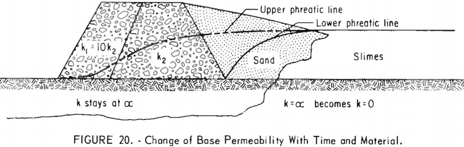
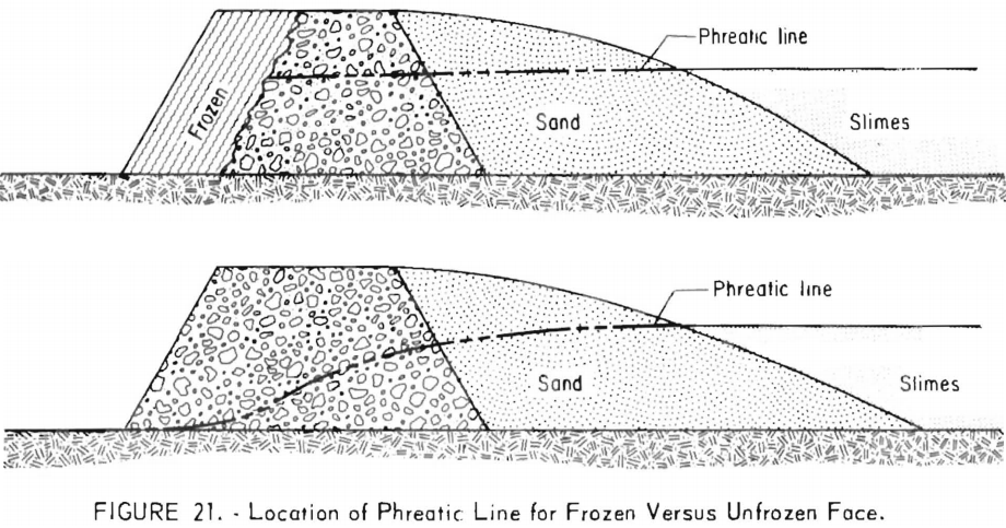
A tailings dam that starts with a permeable gravel base will ultimately develop an almost impervious base owing to the fine tailings percolating downward and the underlying tailings constantly being consolidated (fig. 20). Note that if the sands can be placed near the interior toe of the dike the pervious base remains effective and will function like a longitudinal drain, while the lower phreatic line may be used for stability analysis. If one cannot assure this, the permeability (k) of the entire base approaches zero and the upper line must be used for stability analysis. As this structure increases in height, its condition could change from very stable to very unstable unless the outside is kept free-draining. Frozen conditions can also impair stability (fig. 21).
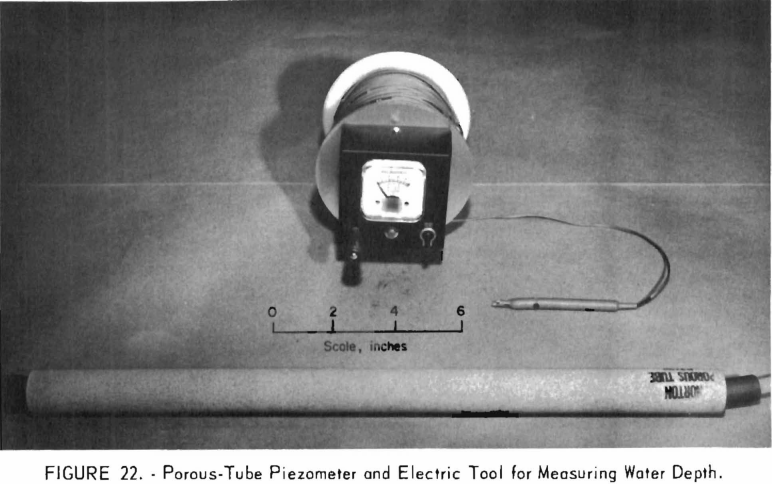
Instrumentation for measuring pore-water pressure and horizontal and vertical movement in embankments is essential in any tailings structure. The location of the phreatic waterline is most accurate when obtained with piezometers (fig. 22) in the pond and berm itself. Checking the water level in a dam in an uncased hole can produce erroneous results. Excess pore-water pressure will not be observed, as the water can dissipate into a coarse sand layer and thus not rise as high as it would in a cased hole or piezometer.
Another important instrument, a slope indicator or crossarm settlement device, is used for the internal measurement of vertical and horizontal movement. Knowledge of the location and extent of movement is essential to predicting the behavior of the structure and to taking any corrective measures that may be required.
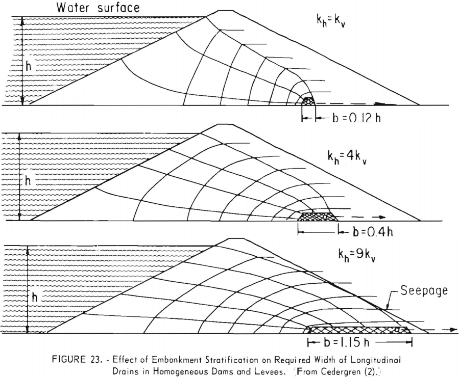
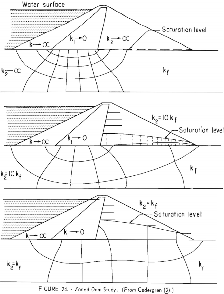
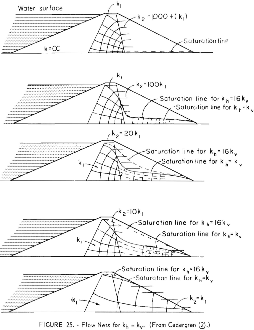
If the dam is to be built in an area for which no in-place information is available, the phreatic surface can be estimated by the solutions of the La Place equations using flow-net construction or the finite element method. Computer programs have been written for the finite element method to predict the location of this phreatic surface line. The program used in this study was developed by R. L. Taylor and C. B. Brown of the University of California (Berkeley Campus) and later modified by J. T. Christian and B. J. Watt of M.I.T. This program utilizes the finite element method to determine pressures and flows as governed by Darcy’s law. Correct hydrostatic head, geometry, and horizontal and vertical permeability according to the inclination and layering are the only input data required for predicting the phreatic surface. Using these values, the computer will search through the numerous phreatic surface lines and adjust pressures at the finite element nodes so that equal potential lines and the phreatic surface can be obtained in a matter of minutes.
Typical phreatic lines that can be developed are illustrated in figures 23-25. Note the effect of embankment stratification and the corresponding horizontal permeability (kh ) and vertical permeability (kv) on the location of the phreatic line and on the required width of longitudinal drain (fig. 23), the relationship between downstream shell permeability relative to foundation permeability and the saturation level in the shell (fig. 24), and the effects of zoning and stratification on the location of the saturation line (fig. 25).
Reclamation
Reclamation of tailings ponds as practiced in the United States varies with each operation and climatic area, though some problems are basic. In several areas the land is returned to as near the original condition as possible, or even improved upon. Elsewhere the goal is limited to the prevention of air and water pollution. Making reclamation an inherent factor in the design of tailings dams may reduce the ultimate cost which must be borne by the consumer. However, reclamation is a study in itself, and a detailed treatment is not attempted in this report.
Considerable research is concerned with promoting the growth of trees, grass, and native foliage in an attempt to beautify abandoned tailings areas. Some tailings are so toxic that it may be years before plant material will begin to grow. In such cases it may be necessary to place a few inches of soil before planting grass or to place an inch or two of gravel to allay the dust while waiting for oxidation and leaching to be completed sufficiently for native growth to take over. The most economical precautionary dust control measure observed to date is the placing of a 3- to 6-inch layer of coarse material, either gravel or mill slag, on top of the pond. The possibility of placing this material pneumatically is currently being investigated. To date it has not been feasible to prevent dust in an active pond.
Conclusions
This survey has resulted in the following recommendations concerning the construction of effective, long-lasting tailings disposal dams:
- Test the foundation soil to determine the subsoil design parameters and to remove any incompetent soils.
- Construct a foolproof decant system that permits visual inspection and, if possible, provides for ultimate surface drainage. The decant circuit should be designed so that if one decant fails an alternate is available to prevent topping, etc.
- Never construct homogeneous dams. Zoned-type construction must be used to control seepage water and consequently increase stability. Since compaction of borrow material in a homogeneous dike is of little value, the money expended should be directed toward zoning.
- Starter dikes should not be built of clay. When the outer shell consists of cohesionless soil (as used with the upstream method), some consideration must be given to compaction to avoid possible liquefaction.
- Most critical in the design of a tailings disposal system is the complete control of both free and seepage water. When impounding low-permeability tailings the disposal area should be large enough that the annual rise will be only a few feet or, as an alternative, two or more areas should be available
so that proper drainage can be attained. The tailings should be distributed around the periphery of the dike through bleeder pipes off the main line, and the pool should be kept as far from the dike as practical. - Dams and ponds should be instrumented and monitored at definite time intervals to check the water movements. The factor of safety can be determined from charts constructed for this purpose. Ponds should be checked at regular intervals, and adequate records and maps showing time, tonnage, and elevations should be maintained.
- Keep the soil permeability constantly decreasing upstream, consolidation owing to overlying tails will automatically cause the decrease of downward permeability. These permeability arrangements affect stability and seepage patterns.
- Because a pervious gravel base will be made ineffective by deposition of slimes and subsequent consolidation as the height of the tailings deposit increases, the minimal estimate must be used in designing the ultimate phreatic line. The higher the dike and the finer the material, the greater are the chances for failure.
A structure that will be stable during the life of the property must be designed for any tailings disposal dam. Furthermore, the system should render the company free of all liability upon abandonment and/or provide for reclamation of the area. Not only is the engineering cost small, but it is also an essential investment since only a few expensive and basically ineffective emergency measures can be taken to avert a developing failure. The development of the associative slope stability and waterflow computer programs have made it possible to design for ultimate conditions of height, slope, etc.
The soils engineering and testing methods that have been well developed for mill tailings disposal systems should be applied, as well as geologic and hydrologic studies.