Table of Contents
In many deep mines, the design of a ventilation system to satisfy the airflow requirements might be difficult to implement and expensive to maintain. The problem may even be more serious when the mine workings are dispersed and located a considerable distance from the surface connections. This problem can be alleviated by including a controlled recirculation system in the ventilation design. Controlled recirculation is a relatively new local ventilation method used to increase the air velocity in a few airways and maintain acceptable working conditions in a mine.
Review of Basic Principles
Controlled recirculation is a ventilation method in which a fraction of the return air from a work area is intentionally passed back into the intake of the same area while, at the same time the volume of air passing through the region is monitored to ensure it remains greater than a predetermined value.
The parameters considered in this design are: (1) recirculation fraction, (2) gas quantity distribution, (3) gas concentration, and (4) booster fan pressure. In the following subsections, these parameters are defined in the manner they are used in this paper.
Study of a Hypothetical Ventilation Network
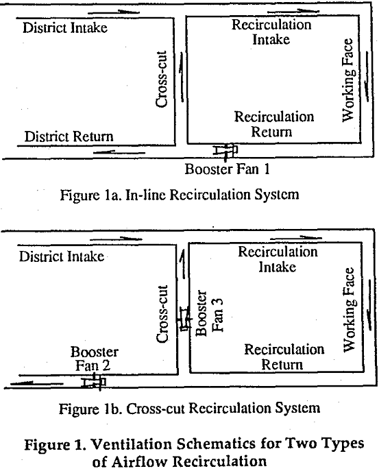
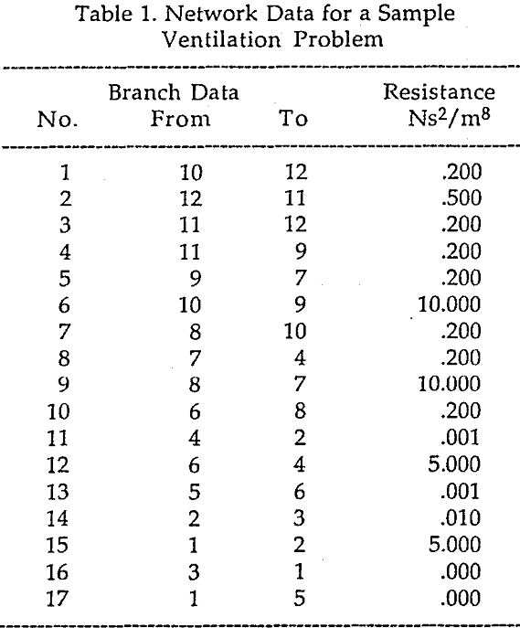
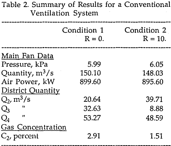
In an attempt to visualize the effect of recirculation on the quality and quantity of mine air, a hypothetical ventilation model was constructed. In this model, it was assumed that all the openings are used to direct the air to a single working face located at the end of a long intake-return system.
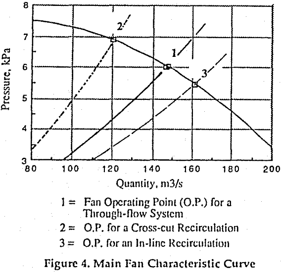
In this system, the pressure difference between the mine intake and return was created solely by the main fan. By changing the resistance of the cross-cut branch, and updating the ventilation model, various flow distribution conditions were generated.
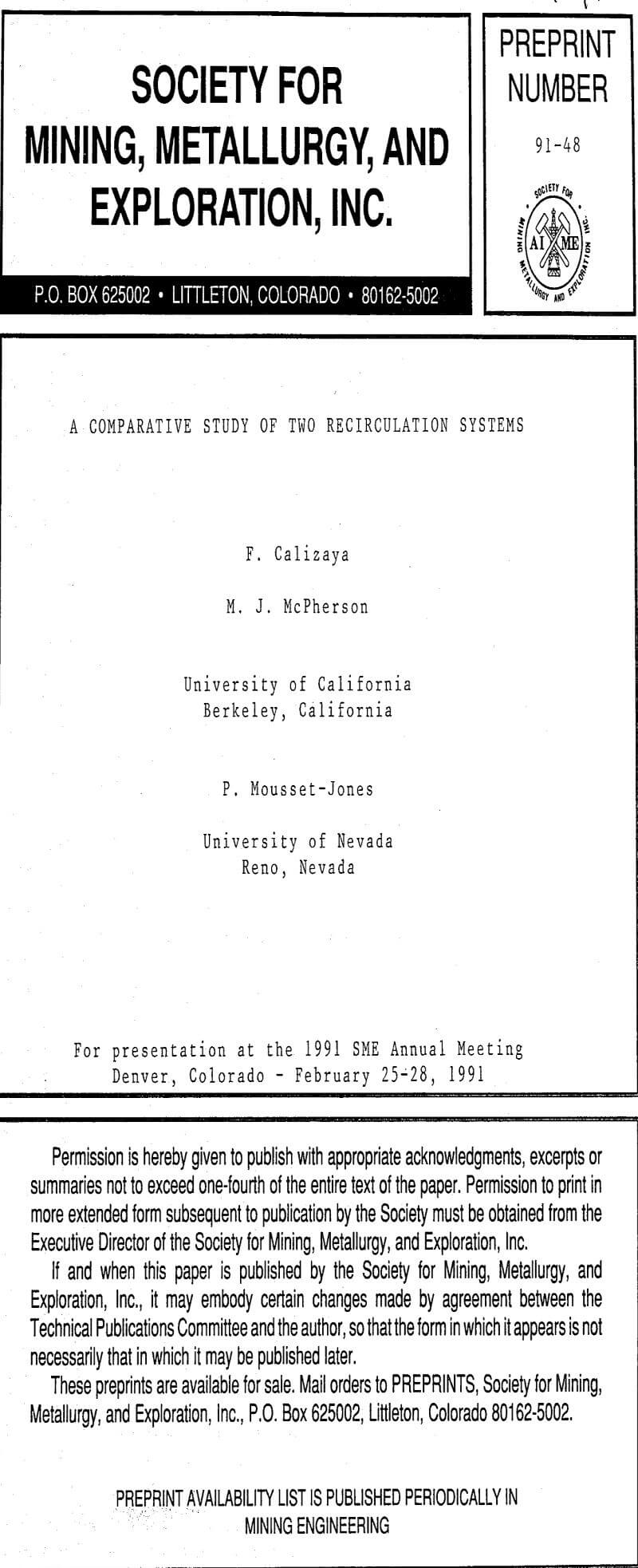
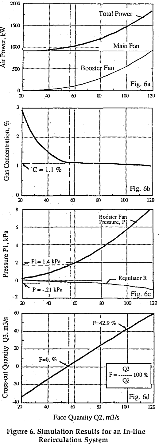
In this section, two recirculation systems are evaluated: In-line and cross-cut. The former involves the utilization of one booster fan, and one regulator. 
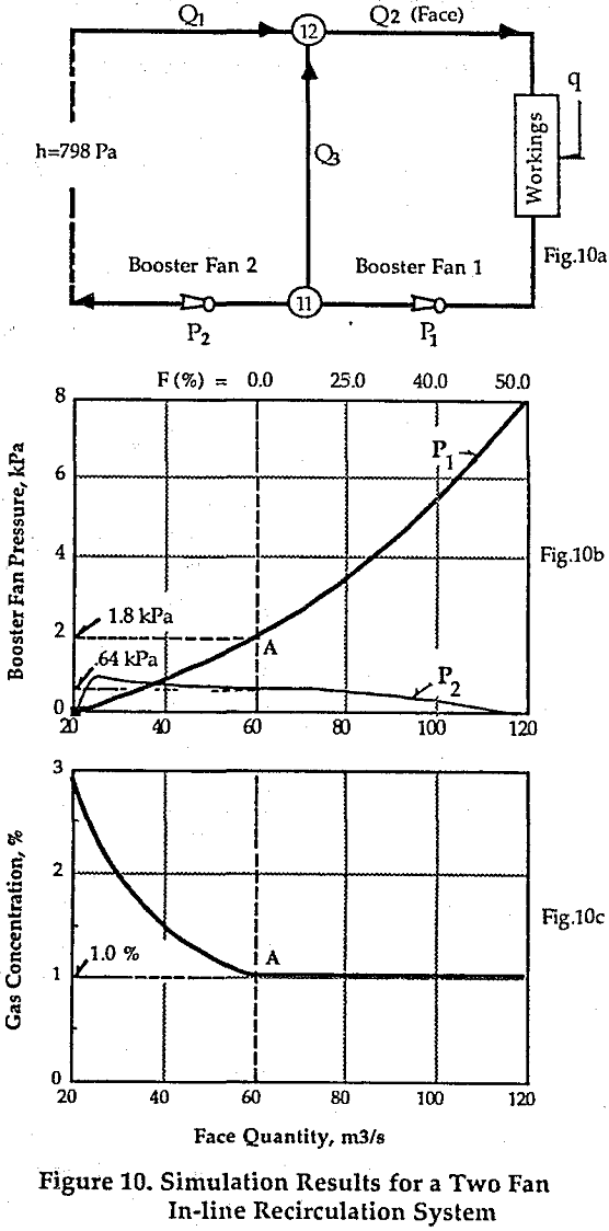
If for a given recirculation fraction the maximum gas concentration in the district remains above the threshold limit value (TVL), then the problem can be solved by adding a second booster fan to the system. This fan should be located in the district return, and sized to handle the required quantity of air (Q1 = q/TLV).
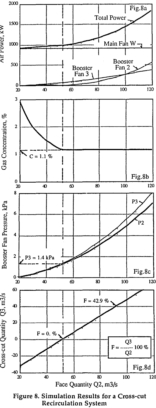
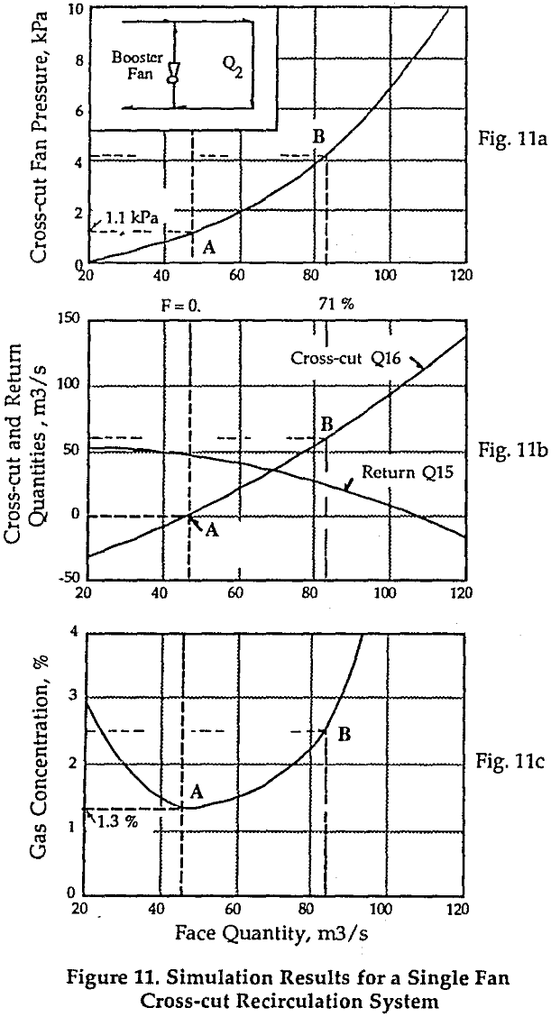
Cross-cut Recirculation: In this case, the recirculation system requires two booster fans: one in the recirculation cross-cut, and another in the district return. The cross-cut fan is sized and positioned to draw part of the return air and pass it back to the district intake. This fan, because of its location, will tend to decrease the flow quantity to the district; therefore, causing an increase in gas concentration at the face.
Special Cases of Controlled Recirculation
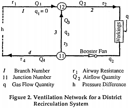
This section discusses the results of four special cases of controlled recirculation: two with in-line recirculation, and two with cross-cut. These cases are investigated to test the stability of each system, and determine the extent to which controlled flow recirculation can be used to solve a district ventilation problem.
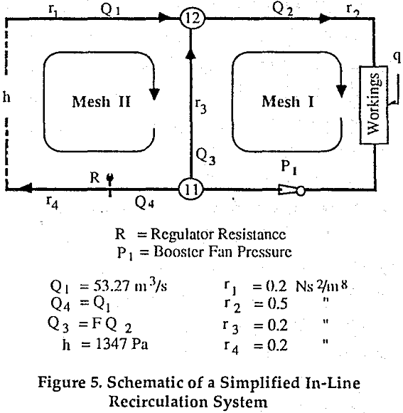
Two Fan -In-line Recirculation: This system includes two booster fans: one in the recirculation return and another in the district return. These fans are sized to recirculate a fixed amount of return air and maintain a minimum quantity of fresh air to the district.
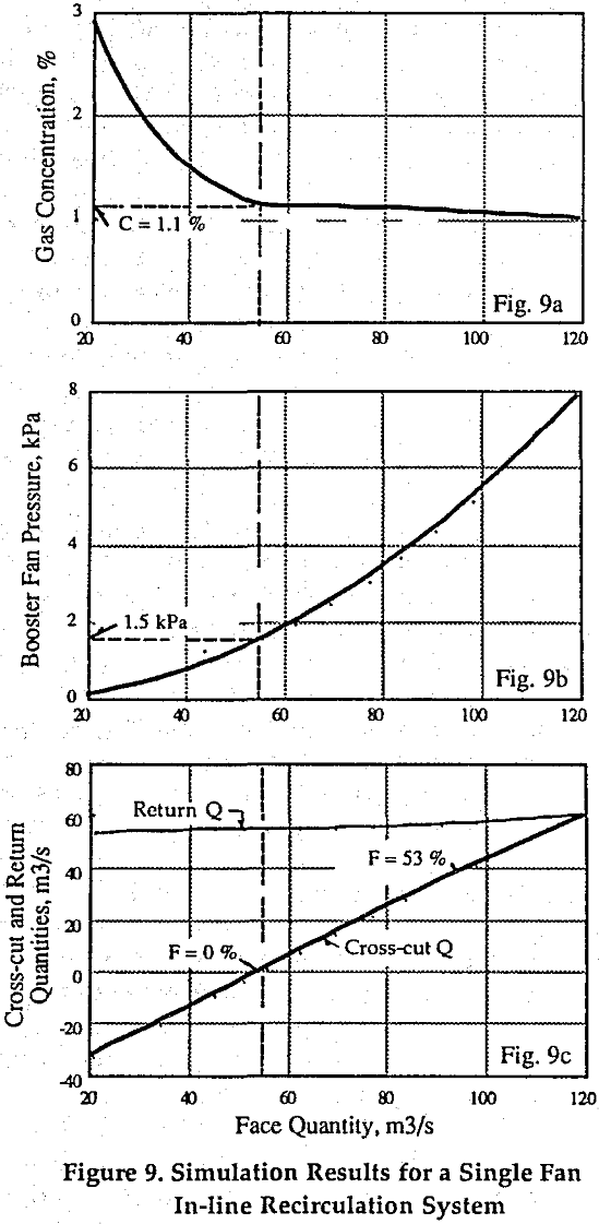
Single Fan Cross-cut Recirculation: This is the simplest recirculation system that could be implemented in a mine. It involves the utilization of one booster fan, the fan located in the recirculation cross-cut.
Modified Two Fan Cross-cut Recirculation: Here, both fans are selected to operate at the same pressure. When this condition is fulfilled, then this, and the single fan-in-line recirculation system will generate identical results. Theoretically, the graphs of Figure 9 can be used to determine the fan duties for both systems. In practice however, the fans of this system may be difficult to select and expensive to maintain, especially when the cross-cut fan is sized to recirculate small portions of air at high pressure. Nevertheless, the principle of equal fan pressure can be used in the preliminary design to reduce the possibility of gas build-up in the district.
Laboratory Tests
These tests were performed at the Mackay School of Mines’ ventilation laboratory model, in Reno, Nevada. To this purpose, the model was rearranged to produce two types of recirculation: in-line and cross-cut. For each type, various flow conditions were generated by changing the duty of the booster fans. During each test six variables were monitored: three flow quantities, two fan pressures and one gas concentration. The results of these tests were evaluated to highlight the benefits and limitations of a controlled recirculation system.
The model consists of a 4-inch diameter plastic pipe ductwork, three Patriot VDC-24 axial fans, an IBM-PC operated gas injection system and an HP 3054 data collection unit. The duct system consists of one intake, two parallel branches: “face”
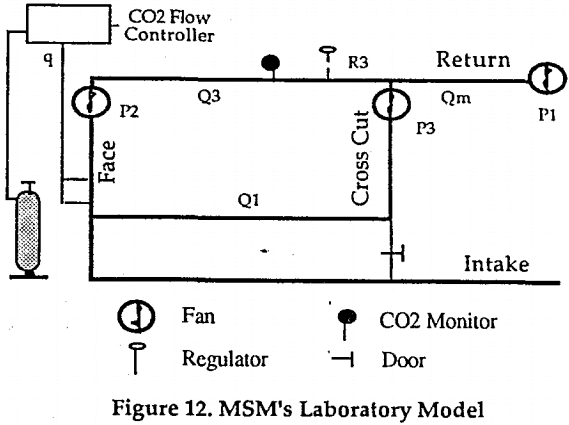
and “cross-cut” and one return. The fan located at the end of the return branch is labeled the “main fan”, it is used to initiate the flow of air in the system.
In-line Recirculation System: In this system, the booster fan was located in the face branch in line with the main fan. It was installed to assist the main fan in providing a larger volume of air to the face. During each test, the main fan was operated at a constant speed (1000 RPM) and the speed of the booster fan varied in five stages. To simulate a working face exposed to a constant gas emission rate, the CO2 injection rate was set equal to 1.25 L/min. This rate was kept constant throughout the experiment.
Cross-cut Recirculation. For this system, the booster fan was located at the entrance of the recirculation cross-cut, it was positioned in such a way that it can draw part of the return air and recirculate directly through the face. Different flow recirculation conditions were generated by changing the capacity of the booster fan.
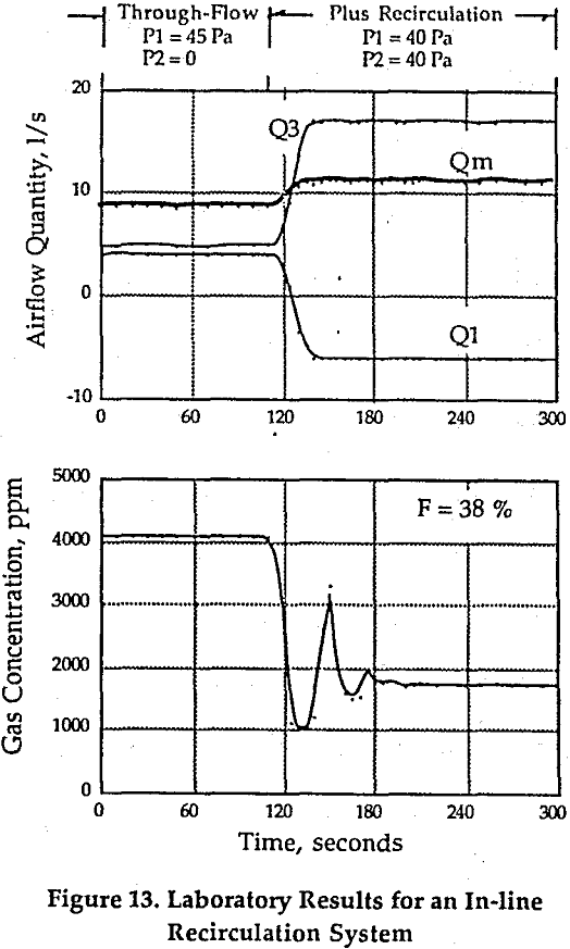
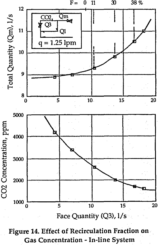
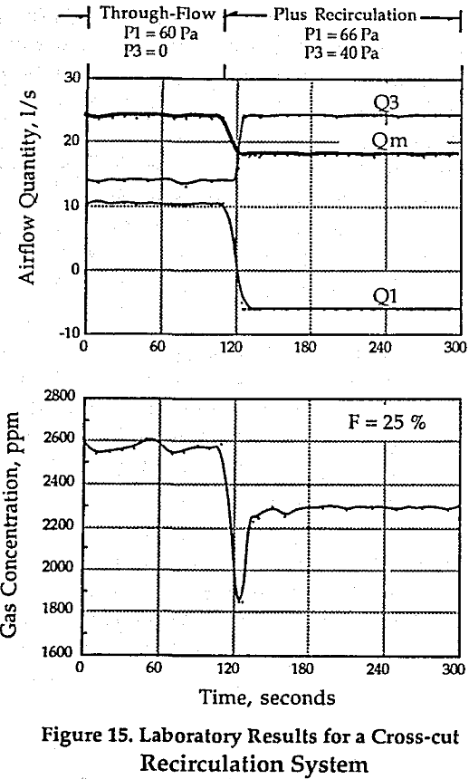
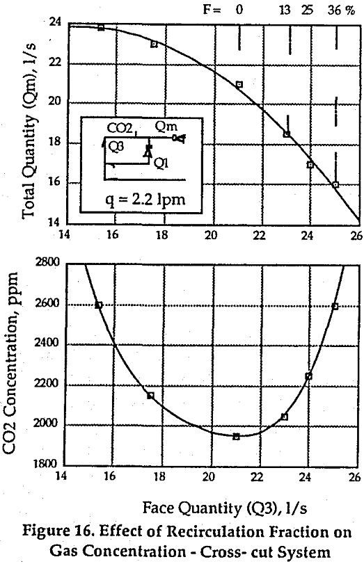
When an in-line recirculation system is used, the operation of the booster fan will increase the quantity of air to the recirculation zone. As more air becomes available, the maximum gas concentration in the zone will decrease. In the cross-cut recirculation, the operation of the booster fan will tend to decrease the flow of air to the district and recirculate more of the return air. For the same gas emission rate, this means higher gas concentration.
The control of air contaminants in a district by recirculation, requires the synchronized operation of two booster fans. These fans should be selected carefully to match the flow requirement and minimize the power consumption. Simple equations such as those presented in this study, can be used to determine the size of these fans.