Table of Contents
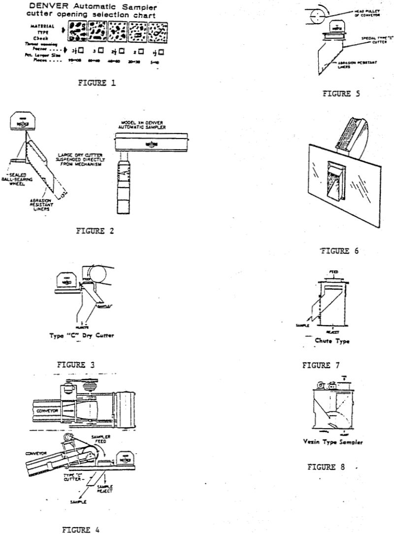
Coarse-ore dry sampling of the type found in primary and secondary crushing systems prior to processing, often requires sampling large flow rates containing 2″ to 6″ particles. The cutter width must be adjustable, with the minimum opening being 2½ to 3 times wider than the largest particle (Figure 1). The cutter blades should enter the flow stream perpendicularly to the trajectory. The cutter discharge chute should be adequately sloped to assure free flow. Typically, this is 50° from the horizontal for a stream containing particles, 60% of which are larger than 1″, with a total surface moisture of less than 10%. When the sample flow is less than 20% coarse material, or if the surface moisture is greater than 10%, a cutter slope of 60° is required.
When sampling large flows (800 to 10,000 TPH) it is necessary to attach a thrust wheel behind the cutter to absorb the impact from the flow. The wheel assembly must be positioned out of the trajectory (Figure 2). If a baffle plate is used, it must also be supported by wheel assemblies. A problem often encountered when dry sampling is that the sample may be contaminated from dust or larger particles falling into the sample chute. This can be minimized by attaching a baffle plate to the cutter.
Liners for cutters can be of abrasion-resistant places, in thicknesses of ¼” to ¾” for sampling materials like iron ore. Stainless steel is typically used in sampling coal. The liner should be made of one piece covering three sides of the cutter discharge chute with the corners having a ¾” radius. The radius corners minimize bridging of fines. Ultra-high molecular weight polymers, which provide good abrasion resistance with a smooth surface to minimize material adherence, can also be used but are difficult to form to radius corners.
Conventional low tonnage (less than 400 TPH) cutter arrangements for conveyor discharge sampling are: front track and end track cutters. The front track cutter (with Type “C” cutter) can be mounted directly on to the conveyor support steel and can be supported entirely by the sampler mechanism (Figures 3 & 4). The end track cutter (with Type “C” cutter) can be used when space requirements dictate that the mechanism must be mounted to one side of the conveyor. The cutter is supported by independent, self-cleaning tracks (Figure 5).
It is possible to incorporate a baffle place in most conventional conveyor discharge chutes (Figure 6). The cutter may be arranged to divert the sample under the head pulley. This is known as an under-burden cutter. An alternative is to arrange the cutter to discharge in front of the head pulley, which is called an over-burden cutter. The cutter will quite often have the baffle plate in the conveyor’s trajectory, requiring the plate to be abrasion resistant or to have a liner similar to high molecular weight polymers.
Enclosed or Chute Type Samplers and Vezin’s
When headroom permits, the chute sampler should be used. It requires a minium amount of modification to the system, and can be installed easily into existing or new chutework. All chute samplers typically have some means of separating the flow stream from the rejects. In the case of the chute sampler, it uses the baffle plate. When sampling dust material, a stationary cutter seal can be placed under the housing’s cover at the cutter’s park position to prevent contamination of sample when the cutter is at rest (Figure 7).
In order to drive large chute type cutters with baffle plates, it is recommended that the sampler mechanism be attached to the baffle plate whenever possible. The plate is supported by anti-friction bearing wheels and offers minimum mechanical resistance which affords a smoother operation. (In light-duty applications the cutter can be driven.)
Vezin samplers use their unique rotary cutter design to prevent sample contamination. A stationary cutter seal at the park position is also included on intermittent models. Vezin samplers are used to sample fine material (-1″), and are available in 5 sizes with capacities from 0 to 400 TPH. Two types are available: continuous units, which take a percentage of the stream passing through the sampler by using continuously moving cutters; and intermittent units, which take a cut at regularly time intervals.
Vezin samplers are commonly used as secondary and tertiary samplers. They can be used as primary samplers in plants (such as cement plants) where small particles exist (Figure 8).
Wet Sampling
Wet, or slurry, sample cutters have some of the same problems chat occur in dry sampling. The cutter must have a large enough opening to easily pass 3 times the largest particles. An important consideration in sizing the wet cutter is that it is hydraulically correct for the application. If the cutter volume is too small, the sample will overflow and the resultant sample will not be representative.
Typical wet cutter widths are ¼” to 1″. Openings of less than ¼” should not be used in applications with greater than 30% solids, due to the possibility of obstructing the cutter blades.
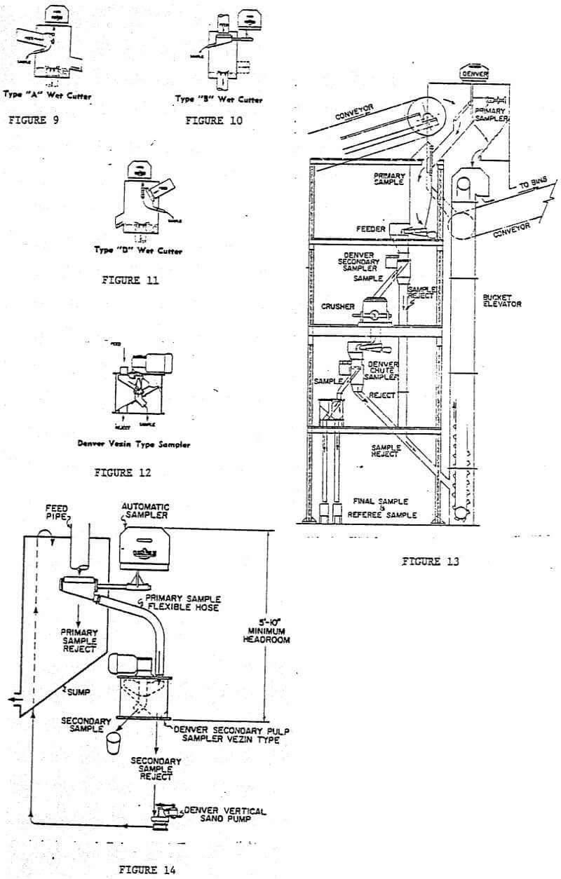
Common wet cutter types are: (1) Type “A” cutter, having a vertical cutter opening (Figure 9). This cutter is designed to sample launders with Che sample discharging under the launder. (2) Type “B” cutter, which has a horizontal cutter opening (Figure 10). It is designed to sample vertical pipe discharges. (3) Type “D” cutter has an opening angled 60° from the horizontal. It can be used to sample steeply sloped launders or pipes (Figure 11).
All of the above wet cutters have nominal size pipe discharges which easily accept a flexible hose in order to transfer samples to a container.
Standard cutters are available for applications from 1 to 5,000 GPM with discharge pipe from 1″ to 6″ in diameter and cutter lengths from 7″ to 30″ long.
Enclosed or Pipe Type Samplers and Vezins
When possible, the pipe sampler should be used. It will simplify the installation, provide a cleaner plant operation, and give a more reliable sample. This type of sample is similar to the chute sampler. It has a housing enclosing the cutter with feed, discharge and sample discharge flanges.
The chute sampler incorporates a Type “A” cutter inside a housing. The cutter has a baffle plate attached and the sample is directed to a sample chamber. The housing’s feed and reject are equipped with standard, nominal pipe flanges. This design is similar to the dry chute sampler.
Wet Vezin samplers differ from the dry type primarily in the cutter design. There is only one size available which is the 16″ model, and can be used for flow races up to 60 GPM. The unit is quite compact measuring only 18″ high from feed to discharge. Standard feed opening is 2½” in diameter and the reject discharge is 3″ in diameter (Figure 12).
This unit is most often used in secondary and tertiary sampling. It is available in the continuous design, taking a 2%, 5%, 10% or 20% sample; and in the intermittent design with a single cutter.
Dry Sampler Systems
The primary sampler is the most important item in a sampling system for it must withdraw a representative sample for further reduction (Figure 13).
In order to have representative sampling throughout the rest of the system, the primary sampler cuts must be combined and fed at a uniform rate. This is done by using a feeder which may be a belt or vibrating type.
Feeders
Belt feeder must have control gates installed after the feed hopper to aid in controlling the feed rate. They also require a speed control device, and for electronic control of the system, a zero speed switch must be installed on the belt co determine if it stops while the system is operating. This type of feeder gives good control capabilities with ores of nearly any particle size.
Vibratory feeders are the least expensive means of obtaining smooch flows. They are capable of handling all sizes of material without being sophisticated in design or requiring much maintenance. When designing it into the chute-work, it is important to feed the unit so that the particles are introduced at the rear of the tray and are moving in the opposite direction of the discharge. There is some particle segregation with this type of feeder but it will not introduce an error in sampling, due to the short time span involved.
Secondary Sampler
Chute type or Vezin samplers can be used depending on particle size. Attention should be given to assure that the interconnecting chute-work from above and below the sampler is dust tight. Tonnage of flow will dictate the size sampler used.
Crushers
Several types of crushers are used depending on the material being sampled. A unit used for reducing larger particles (3″ to 6″) is the “Jaw” crusher. It can be choke fed, not requiring a uniform feed rate, but is limited in the fineness of product discharge, which is typically about ¾”. A secondary crusher, such as a roll crusher or pulverizer, would be needed to produce a -10 mesh product suitable for analysis.
Gyratory crushers can be used as primary crushers with much the same results as those of the Jaw crusher.
Hammermills are quite often used to reduce particles co the desired fineness in one pass. In using this unit certain considerations must be given to the chute around the feed and discharge. Hammermills act like fans pulling air from the bottom and blowing it out the top which can cause dust to escape from the system. To reduce this a run-around, or by-pass, air duct must be installed between the feed and discharge chutes. Angles of the duct must be 60° so that fines will not collect inside and obstruct air flow. This should be sized to handle the cubic feet of air passing through the crusher.
Tertiary Samplers
At this stage of sampling the Vezin sampler is a fine selection considering the ore is of a size most agreeable to the design. A feeder should be installed ahead of the sampler to insure that the cutter is always taking a portion of the flow.
Rejects
Rejects from the secondary and tertiary sampler will be combined and returned down stream of the primary sampler or far enough up stream so as not to be sampled with the same consignment. The rejects may be returned by a belt feeder or a bucket elevator.
Chutework
There are some basic rules that should be observed:
- Angles should be 60°.
- Internal welds should be located out of the area of material contact.
- Sloping sections and transitions should have rounded corners.
- Chutes subject to coarse material flows (+1”) should be 3/16” or ¼” thick. Areas handling -1″ material can be 10 gauge.
- All connections should be flanged and gasketed.
- Adequate clean out and inspection doors . should be provided.
Sample Collector
A collector should be used co contain the final sample. Individual sample containers should be of a type that do not require emptying until received at the laboratory, thus minimizing possible contamination.
Electrical Controls
A central control panel is necessary for operation of the system. It should be remote from the system and located in a separate and dust-free room. It will have timers for samplers and the collector, push buttons for samplers, feeders, crushers, etc.; with an interlock circuit chat will stop all equipment ahead of any item that is stopped due to an overload, allowing the rest of the system to operate and clean itself out. The motor control center should be located in the same cabinet or in one beside it. This would house the motor, starters, overload equipment, and transformer.
Wet Sampling Systems
Primary Sampler
Typically, the primary sampler is a single cutter located at the discharge of a pipe or launder. It can be a cutter incorporated Into an existing launder of a pre-engineered, enclosed pipe sampler. In either case, it is nearly always of an intermittent operation due to the large flow rates being sampled. The discharge of the cutter can be piped directly to the secondary sampler using flexible hose.
If the cutter travel is over 30″, the sample should be discharged into a small tank and then piped to secondary sampling. This will take up less headroom and require less maintenance on the primary sampler.
Secondary Samplers
If flow races are below 60 GPM, a 16″ Vezin can be used. If the primary sampler is taking intermittent cuts, this sampler should operate continuously to insure an accurate sample is taken. The secondary sampler can only be operated intermittently if it is receiving a constant uniform flow (figure 14).
Interconnecting Pining and Tanks
Piping from primary to secondary samplers, for the most part, can be flexible hose. The overall length should be kept as short as possible (6’0″ or less). If long sections are necessary, intermediate supports must be used to reduce the load being supported from the primary sample cutter. It is preferable to discharge the sample into a small cone bottom tank and then pipe the sample to the secondary sampler.
Rejects
The rejects should not be reintroduced into the system. The most practical solution is to use a pump to transfer them to the primary rejects. In some cases it may be possible to use launders or shallowly sloped pipe to return rejects down stream of sampling. Care must be taken to assure the launder and pipes do not sand up. For clean up purposes, to open the launder is more appealing.
Sample Collector
This can be as simple as the individual would like. Often, an open bucket is used. It is desirable to have this container fitted with a cover to prevent contamination.
Controls
There is no need to have a sophisticated remote control panel to use with wet sampling systems. Electrical control may be located with timers, push buttons, and transformer in a single box.