Table of Contents
Mill feed averages 0.7% Cu, primarily as chalcopyrite, and 0.024% Mo. The copper concentrator produces 1050 mt/day of bulk Cu-Mo concentrate averaging 27% Cu and 0.6% Mo. Molybdenum plant feed is thickened to 62% solids and stored in two 150 cubic meter tanks. Two identical flotation circuits are fed from a constant head tank through changeable orifice plates thus maintaining steady feed rates. Each circuit consists of conditioners, rougher flotation, and seven stages of countercurrent cleaner flotation. The final copper product, the combined first cleaner and rougher tails, is filtered to -12% moisture and shipped by rail car to various smelters. The molybdenum concentrate averaging 43% Mo is spray dried in NIRO atomizing dryers and barreled for shipment.
Test work on flotation air requirements in the molybdenum plant indicated that the use of nitrogen in open flotation cells without any means of recycling the nitrogen would be uneconomical at bulk nitrogen prices. Less expensive nitrogen sources were considered, including a nitrogen generator, by-product nitrogen from a nearby oxygen plant, and boiler exhaust gas. These proved unacceptable due to high capital costs and/or additional costs associated with upgrading the purity of the nitrogen gas products. It appeared that recovery of nitrogen at the top of the cells for reuse was the most promising approach.
Nitrogen Flotation System
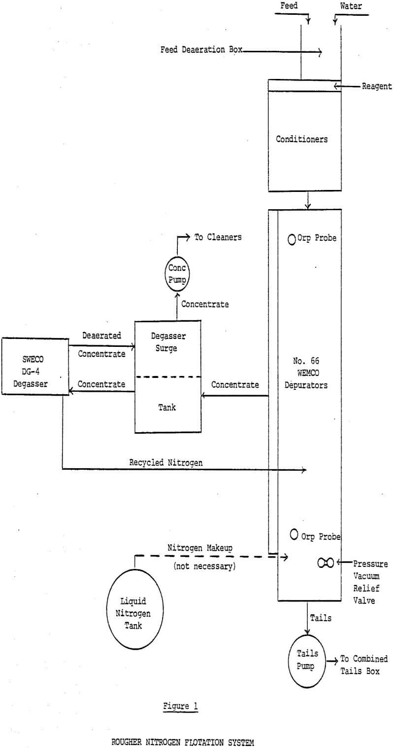
The system was installed outdoors for ease of installation, to avoid possible problems with excess nitrogen in the plant atmosphere, and to ensure that both original divisions remained operational in case of failures in the test system. The WEMCO machine was supplied as a self-supported, all-steel skid mounted tank with integral float collecting launders and gas tight covers. WEMCO made several modifications in the standard Depurator design to adapt it to minerals flotation. The normal four-cell row configuration for Depurators was modified to an eight-cell row to yield sufficient flotation time and to minimize short circuiting. The eight-cell row consists of seven 1 + 1 No. 66 mechanisms plus one ship prop mechanism in the last cell.
Steel inspection doors with rubber seals were provided along the length of the collection launder so the operator could check his flotation levels. Opening the doors caused a change in system pressure and thus level changes. Additionally, opening the doors allowed reagent-consuming oxygen to enter the system. To obtain good metallurgical results with the enclosed cells it was necessary to install glass windows in the inspection doors so they could be left closed.
Sweco designed a rougher concentrate surge tank to be installed between the cells and the degasser. The surge tank is partitioned into two compartments; one for froth and one for degassed pulp. Depending on the amount of new concentrate entering the degassing system, some degassed pulp is automatically recycled back to the feed compartment to ensure steady feed to the degasser.
Depressant Consumption
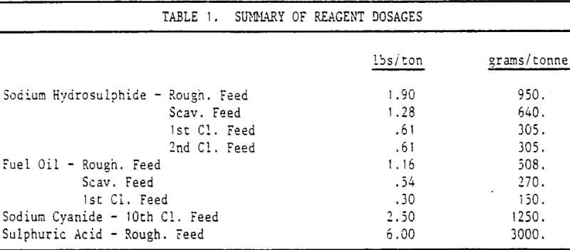
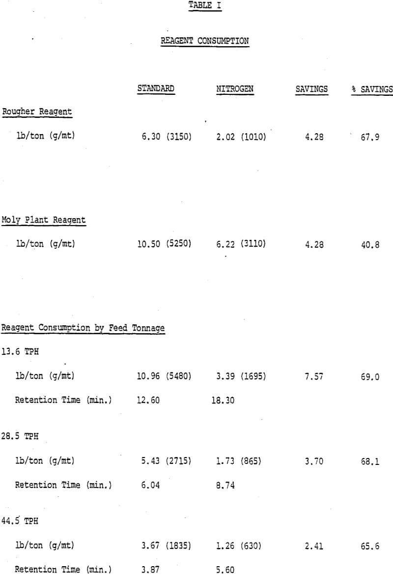
Depressant consumption in rougher flotation was reduced from 6.30 to 2.02 lbs/ton (3150 to 1010 g/mt), a 67.9% reduction, using the enclosed flotation cells. The depressant consumption data are presented in Table I. While the results were lower than the 75% reduction originally predicted, the reduction will still enable reagent cost savings of over $400,000 annually if both rougher banks are converted.
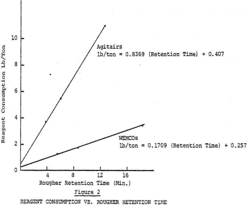
Since the retention time and tonnage treated are directly related, the tonnage effect on depressant consumption can be illustrated by plotting depressant consumption as a function of pulp residence time. Depressant consumption was reduced sharply at higher tonnage (left side of graph) as retention times dropped and each unit of pulp was exposed to air for a shorter period of time.
There has been considerable discussion in the past about how much depressant is required for actual copper depression. The nitrogen system depressant consumption would have been a close estimate of this “base” rate if not for the small amount of air entering the system.
Metallurgical Results
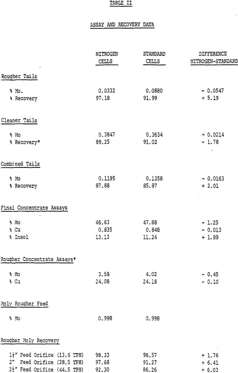
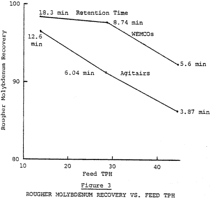
The extended rougher flotation time of the WEMCOs resulted in 5.19% better rougher molybdenum recovery. See Table II for metallurgical results. Average retention times were 10.3 and 7.1 minutes for the WEMCOs and Agitairs respectively. The better rougher molybdenum recovery obtained was apparently due to recovering slower floating fine molybdenum and locked molybdenum- insol particles. The rougher recovery differences on different ore types varied from none to 20% in favor of the long retention times reflecting varying amounts of the two slow floating molybdenum constituents. Due to the difference in retention times between the two rougher banks the effect of nitrogen on molybdenum recovery cannot be evaluated.
Role of Nitrogen in the Flotation of Molybdenite
The use of nitrogen in molybdenite flotation circuits is a relatively new concept utilized by only a few mines around the world. This paper briefly discusses circuit chemistry and the reason for its success. It follows the entire testing process which resulted in a sodium hydrosulphide dosage reduction from 18.5 to 4.4 lbs/ ton (9250 to 2200 g/t) through to the final installation of an inert gas generator which will produce reagent savings in excess of one million dollars annually.
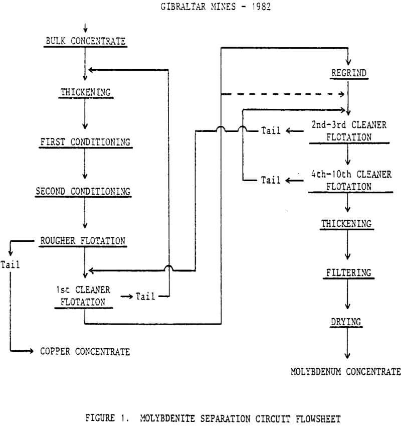
Flowsheet
Feed to the molybdenum flotation circuit is a bulk concentrate of 27% Cu and 0.9% Mo at 55 to 60% -325 mesh produced with the use of sodium isopropyl xanthate, fuel oil, aeroprotnoter 3302, and frother MF-142.
Sodium hydrosulphide and fuel oil are stage-added throughout the roughers and first cleaners. Sodium cyanide is added to the 10th cleaner for control of the copper content in the final concentrate.
Originally, all pumps used within the circuit were SRL centrifugal type in conjunction with flat bottomed pump boxes. Some of these were changed to direct pumping with the intakes being fed directly from the concentrate launder. Others were replaced with vertical pumps mounted down into the boxes.
Circuit Chemistry
To rationalize the use of nitrogen in such a flotation process, it is necessary to study some of the chemical reactions.
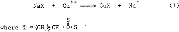
In the bulk circuit 0.013 lbs/ton (6.5g/t) sodium isopropyl xanthate is adsorbed on to the copper mineral surfaces. The cuprous xanthate formed in the following reaction produces a hydrophobic particle which is readily floatable.
The collector coated copper concentrate is re-ground, up-graded, thickened, and then fed to the molybdenum circuit. The two processes of conditioning and acidification are used to decompose much of the cuprous xanthate and reduce copper floatability. Since this is not 100% effective, sodium hydrosulphide is added.
One more factor must be considered in the choice of gases used for flotation. Sodium hydrosulphide is very readily decomposed by oxygen in an aerated pulp. The 290 cfm (.137m³/s) air used in this particular flotation circuit supplies more than enough oxygen to consume most of the NaHS.
Suffice to say, most of the preceeding has been strictly conjecture. It is no more than a plant operators idea as to what he feels takes place. We know it works, and very successfully. However, I will leave it to the researchers, and academics to tell us why.
Nitrogen Testing
The first test was designed to find out what effect nitrogen had on a flotation circuit and how to handle this particular gas. Three AT-10 cylinders of liquid nitrogen, 30,000 cu.ft. (849m³) gas equivalent, were hooked up with an ambient vaporizer to the air header. Within two minutes of turning the gas on a definite visual change became evident. Copper which usually floated in the last couple of cells was immediately depressed and replaced with a thin layer of molybdenite.
A second test was planned to study the real effect of an inert gas on hydrosulphide consumption once the residual circulating load had been eliminated. The equipment used for this run was two tank trucks of liquid nitrogen, a propane- fired vaporizer, and a 3″ feed line as opposed to a 1″ line in the first test.
Average gas flow was 360-375, cfm (.17-.177m³/s) up from 245 cfm (.116m³/s) in the initial run. It resulted in a 77% hydrosulphide reduction and improved metallurgy. The large difference in gas flow rates raised questions concerning optimum flow for good flotation.
A third and final test was scheduled with several objectives in mind:
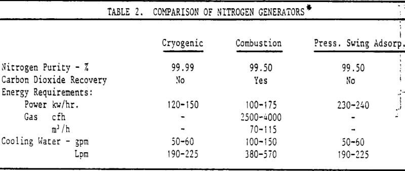
- There were a number of types of generators available with different by-products and varying gas purity. What purity of gas was acceptable to our circuit?
- In order to size the generator, what range of gas flow was required?
- A large capital expenditure of this nature required further confirmation of the previous results.
One type of nitrogen generator being considered was the cryogenic unit which in most cases produces a 99.50-99.99% pure gas. Generally, the higher the purity, the more expensive the operation. Various nitrogen:air ratios up to 15% air were tried while observing the effect on NaHS consumption. It was found that a maximum of 2½-3½% air, (0.5-0.7% O2) could he tolerated without a significant increase in reagent.
The concept of nitrogen usage started out strictly as an economic advantage to cut costs. The initial direct benefit was seen to be a 76% reduction in sodium hydrosulphide. This was followed by the replacement of sulphuric acid with the carbon dioxide.
Long term evaluation has proven the circuit runs more smoothly and is easier to control while using nitrogen. It is generally known that an over dosage of sodium hydrosulphide will start to depress the molybdenite. We feel this occurred frequently during the use of air and high quantities of NaHS. This rarely occurs now at the lower dosages and is easily recognized.
Combining these factors, and probably others, a 41 recovery gain has been established with the use of nitrogen while maintaining the same concentrate grade.
Work is currently under way to study the pulp potential, emf, for both air and nitrogen as a function of hydrosulphide concentration. It is possible this will lead to closer reagent control and improved metallurgy with ultimate control by on-stream analysis and computer.