Table of Contents
The past 15 years have seen rapid advances in the metallurgy of materials for drill machinery and bits, but rock drilling itself continues to be largely an art. Jet piercing, roller bit rotary drilling, and rotary percussion are all promising new techniques, but the percussion rock drill, still used for 90 pct of the blastholes in U. S. hard-rock mining, has undergone no major modification since pneumatic machines were first used successfully in the 1860’s.
Basic Concepts
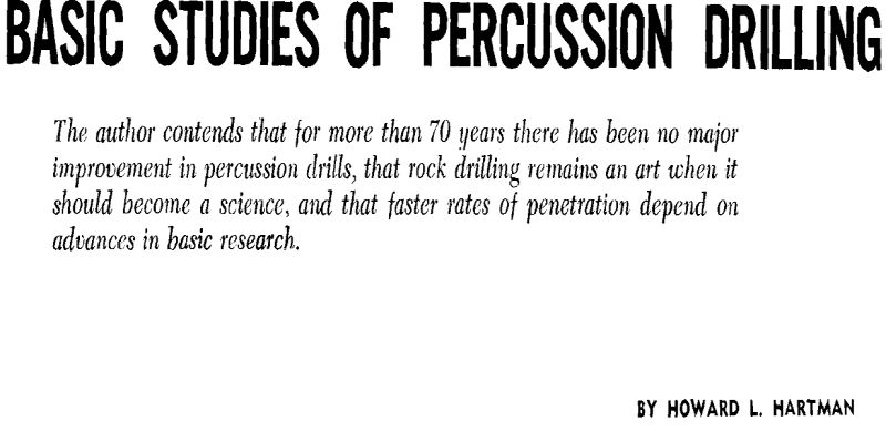
The formation of a crater in rock under the impact blow of a bit can be observed experimentally. Directly beneath the edge of the bit the rock is crushed into fine powder; toward the sides of the crater it chips out into relatively large fragments.
With a sharp, wedge-shaped chisel bit the same phenomena of rock failure are evident as with the die-shaped bit, but essentially they occur simultaneously instead of successively. The crushing and chipping processes follow many times in succession, almost continuously, until the blow energy is dissipated. The outward appearance of the crater is the same, but somewhat less subsurface damage (fracturing, cracking, and crushing) occurs.
Rock failure under an impact blow appears to be related to the number and magnitude of local flaws or cracks in the rock structure and to their distribution geometrically about the line of load. As the bit penetrates the crushed zone, stresses build up in the adjacent solid rock until a crack propagates from one of the points of stress concentration and a chip is formed.
It is highly desirable to obtain a mathematical relation between energy of blow and depth of penetration, cross-sectional area, or volume of
crater for any shape of bit. This relationship is needed to determine an expression for the rate of penetration of a drill bit, since the amount of rock broken out per blow per unit of time is a measure of drilling speed.
The procedure is demonstrated below for the wedge, a typical bit shape:
Let l = length of cutting edge and
θ = included angle of wedge;
then α = 2 lh tan θ/2 and
F = fa = 2flh tan θ/2;
therefore, w = ∫ 2flh tan θ/2 dh.
Integrating, E = flh² tan θ/2
and
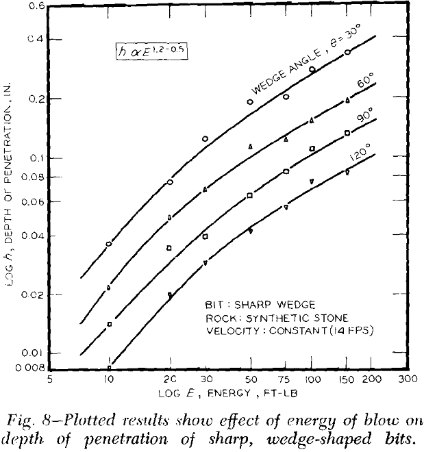
h = √E/fl tan θ/2
This relation demonstrates theoretically that the depth of penetration is inversely proportional to the square root of the tangent of half the wedge angle, but more important, it shows that the depth varies directly as the square root of the blow energy, or h ∝ E½. Further, it can be shown that since l is independent of h and since the cross-sectional area of the crater varies as the square of h, the volume of the crater V is directly proportional to the blow energy: V ∝ E. This demonstrates the dependence of crater formation on blow energy.
Those factors in drilling which can be grouped under blow dynamics include: 1) energy, 2) velocity, 3) mode of transfer, 4) force, 5) contact time, 6) momentum, 7) impulse, and 8) acceleration. All these factors may influence rock failure and crater formation and hence rate of penetration in drilling. The first three are reported experimentally in this article.
The ultimate goal of fundamental studies of rock drilling is to achieve faster rates of penetration by increasing knowledge of the basic mechanism of rock penetration. Another objective is to predict or calculate rates of penetration from basic parameters of the process.
To date there have been two formulas developed to express the linear rate of penetration, S, of a multi-wing chisel bit. One, reported by Simpson and Parry, is in terms of the average distance of advance, d, of the bit per blow:
S = WdB/B/R = WdR
where R is frequency of rotation and B is frequency of reciprocation. A second, proposed by Battelle involves the average cross-sectional area of crater A broken per wing at the periphery of the bit:
Experiments With Drop Tester
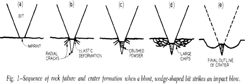
The principal laboratory equipment used in carrying out the present investigations was an impact drop tester, calibrated to obtain a wide range of blow energy, velocity, and load. Bits of the desired shape were attached to a weighted plate and permitted to strike blows on rock specimens. Synthetic stone was used for the entire series of tests, prepared from high, early-strength cement and FF-grade pumice in a 4:1 weight ratio that averaged 5000 psi compressive strength. The use of synthetic stone reduced the effects of heterogeneity and variability between specimens and still faithfully demonstrated the mechanism of failure in rock types such as shale, siltstone, and the younger sediments whose behavior is termed both brittle and ductile.
Before each test, the rock specimen was clamped in the position desired for receiving the blow. The height of fall to produce the required velocity and energy of blow had been previously calculated and the plate was raised to that height. A cardboard cylinder was placed on the rock at the location of the intended blow to prevent scattering of cuttings. Then with the desired bit attached to the plate, the blow was struck.
Discussion of Test Results
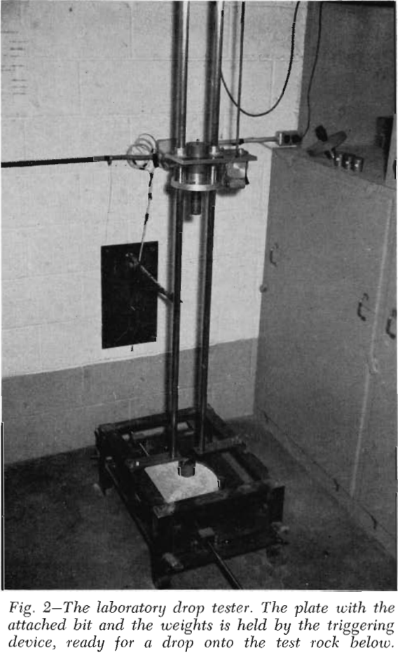
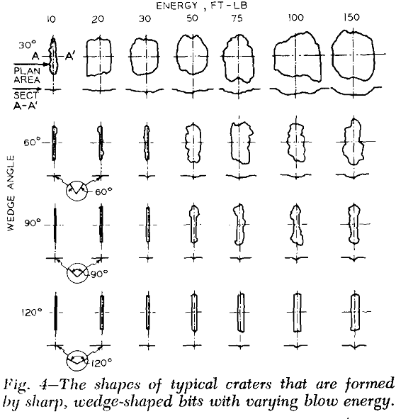
Bit Shape, Wedges: The importance of the included angle of sharp, wedge-shaped bits on crater formation was confirmed. As the blow energy was varied with bits of different angles, two separate and distinct phases in the cutting action were observed, namely, the crushing and chipping phases. This behavior can be seen in the sketches of typical craters, which may be summarized as follows:
- Both crushing and chipping were not obtained with all wedges—the 30° wedge always penetrated by chipping, whereas the 90° and 120° wedges never left the crushing phase, even at high blow energies.
- Craters were formed principally by crushing or chipping; some chipping occurred when crushing was predominant (particularly at the ends of the pit) and crushing continued even after chipping began, but there was a fairly sharp demarcation in cutting.
- Chipping did not predominate until a certain energy level was attained; this was low with the 30° bit and apparently infinite with bit angles greater than 90°.
- There was similitude in the crushing or chipping phase for a given bit, although at the highest blow energies (150 ft-lb) the craters appeared to deepen with little or no increase in volume.
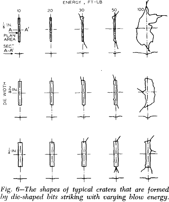
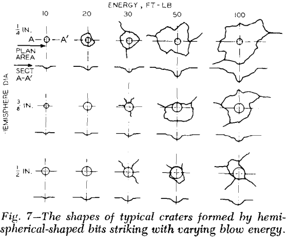
Dies and Hemispheres: The other two shapes of bits behaved in a manner similar to that of the wedge. The appearance of the craters revealed a predominance of either crushing or chipping at various energy levels, although the transition between the two phases was less sharply de-
fined. More radial cracking was observed with these bit shapes than with the wedges, indicating a proportionately higher expenditure of energy for cracking than for crater formation. There was a strong tendency with both dies and hemispheres for adjacent craters to index across at higher blow energies. Rebound was not significant (less than 1 pct) with any bit shape.
Blow Transfer: As the following data show, crater formation was considerably improved when velocity of the falling mass was imparted to the bit:
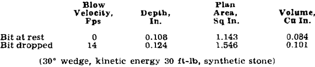
When the bit rested on the rock and the falling weight transferred the energy of the blow to the bit, the volume of crater produced was only 84 pct as large as that formed when the bit was attached to the falling weight and struck the rock at high velocity. The craters were similar in appearance but narrower when the bit was at rest.