Table of Contents
Pneumatic stowing was first introduced in longwall mining in the middle twenties. Since that time it has advanced through many stages of development, particularly abroad, which have greatly improved its efficiency and contributed to its growing use. Pneumatic stowing originated in coal mining but has also been adopted in metal mining.
Pneumatic Conveying of Stowing Material
Basically, pneumatic conveying is the flow of a two-phase, solids-gas stream in a pipeline. The flow is influenced to a large extent by the properties and dimensions of the two phases. Similar to hydraulic transportation, the presence of solid particles in a gas stream affects the flow velocity, the degree of turbulence and the pressure drop in the conveying system. The pressure drop increases with the solids loading, but disagreement has always existed as to whether or not the increase is a linear function of the weight of solids present.
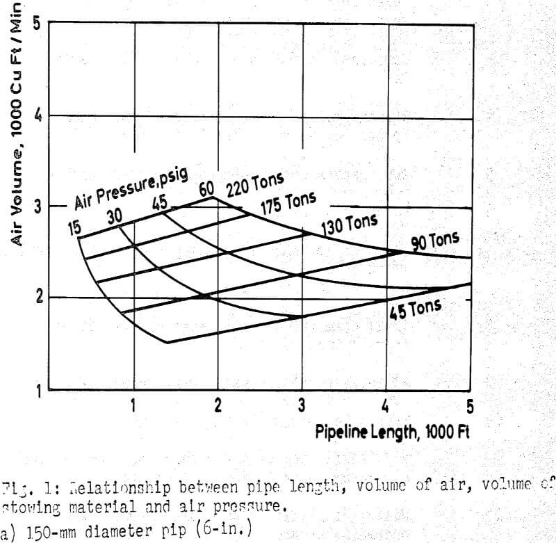
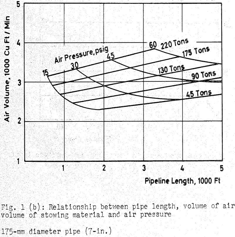
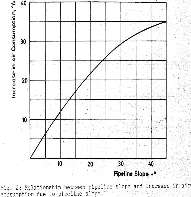
The effects of various parameters (such as pipe diameter, length and slope, the size, shape and load density of solids, air velocity, etc.) on friction losses in a pneumatic conveying system are not completely understood. There are marked differences between the findings of the various researchers, and attempts to correlate various theories have been so far unsuccessful.
The obvious disadvantage of pneumatic stowing is the high consumption of air and resulting high power costs. To assure an undisturbed operation of other compressed air equipment, it is generally advisable to install a separate compressor for pneumatic stowing installations, or where possible to schedule the stowing operation for hours between production shifts. Installation of a separate compressor plant, close to the underground stowing machine, reduces air losses in long pipelines. However, it presents other problems: (1) The intake air contains more dust, (2) Smaller compressors have lower efficiency, and (3) Heat generated by compression must be dissipated.
Pneumatic Stowing Installation
The function of the stowing machine is to feed the material into a pipeline. Transport and emplacement is the function of the air stream flowing at high velocity through the pipeline.
There are three basic types of stowing machines: bunker type, compartment type, and rotating wheel type.
The bunker type stowing machine has a large storage bunker (capacity 650 to 900 tons). The tank is filled through a gate on top. The gate is closed and a compressed air intake valve is opened. The stowing material, under pressure in the tank, is fed into the air-stream by a vertical rotating wheel.
The compartment type stowing machine has two superimposed compartments. A batch of material is received into the upper compartment and dumped through a gate into the lower compartment. The rotating wheel feeds the material into the air stream. The gates of the compartments are operated in cycles, one gate always being in a closed position.
Stowing Material
The properties of stowing materials have a definite influence on the wear of pipe and on the capacity of stowing machines.
The best packs are produced by soft partially decomposed rocks which contain a moderate amount of clay. Fill material containing sulphide minerals will produce a very good pack as the result of the cementing action of the oxidizing sulphides.
The maximum density of pack is obtained in the immediate vicinity of the point of impact of discharged material. The fill in this target area has a very low percentage of voids – about 10 to 15% at higher velocity of discharge. Outside of this zone the percentage of voids rapidly increases to between 40 and 50%,and the characteristics are simply those of a pile of loose material. It is important that the discharged fill be distributed across the face of the filled space.
Retaining of Stowing Material
Pneumatically placed material has a low moisture content. It does not develop the hydrostatic pressure and does not escape through leaks in retaining structures during the stowing operation.
Stowing material discharged at high pressure will stand vertically without a retaining structure when adjacent ground is blasted alongside the previously placed fill. This tight dense packing can be obtained when discharging fill at high velocity into an unobstructed space.
When backfilling follows extraction and the mining face must be maintained free, a retaining structure must be placed between the face and old fill to confine the stowing material.
In longwall mining the retaining fence is placed parallel to the advancing face. In the simplest structure, the fence is made from chicken wire fence nailed to posts. There are also special fence webs for pneumatic stowing. Among these are wire mesh interwoven with paper or covered with paper. Link fence can be easily rolled down and re-used when filling is completed and posts are removed.