Table of Contents
Cobalt is a critical and strategic metal because of its essential defence related uses and the high degree of U.S. import reliance for its supply. Currently, the United States does not produce any cobalt from domestic mines. Most of the U.S. supply of cobalt is imported from the African nations of Zambia and Zaire CO-4 Recent trends make it desirable to reduce this country’s dependence on foreign sources of critical metals by developing technically and economically feasible processes for treating domestic cobalt ores.
A major domestic cobalt deposit is located in the Blackbird district, Lemhi County, ID. A report published in 1962 showed an estimated deposit of 15 million lb Co in blocked-out ore, plus 225 million lb Co in indicated and inferred ores. Later work by Noranda Mines Limited indicated that the deposit contains enough ore to support production of 4 million lb Co per year for 20 years. No other known deposit in the United States has cobalt as the primary metal. During the 1950’s, this deposit was mined commercially by the Calera Mining Co. Unfavorable economic conditions and technical difficulties, mainly the formation of large “sulfur balls” in the reactor which damaged the lining, resulted in the termination of this operation in 1959. In 1977, Noranda began redevelopment of the deposit, conducting extensive drilling and metallurgical testing. Noranda devised a process for treating a concentrate containing 0.36 pct Cu. This process comprised oxidative pressure leaching at 155° C and conventional precipitation techniques for cobalt recovery. No attempt was made to recover the copper. Because of unfavorable economic conditions, the mine was put on caretaker status in 1982.
In 1979, the Bureau undertook laboratory research to develop a process to recover cobalt and copper from a concentrate supplied by Noranda. The supplied concentrate had a 10-fold higher copper concentration than that used in the Noranda research and was similar to that used in the Calera operation. Leaching of this concentrate at 155° C resulted in the formation of the troublesome sulfur balls. Since there is some doubt as to whether a typical concentrate will have a high or low copper concentration, the Bureau’s research objective was to develop a leaching process that would not produce the sulfur balls and also to devise alternative technology using solvent extraction to recover cobalt and copper by a method other than that of conventional precipitation.
We conducted bench-scale research on a process for treating cobaltite concentrates, comprising:
- oxidative pressure leaching,
- jarosite precipitation followed by H2O2 oxidation and pH control to remove iron and arsenic,
- copper solvent extraction with a mixed hydroxyoxime-amine extractant,
- copper electrowinning from recirculating acidic strip liquor,
- selective cobalt extraction from copper solvent extraction raffinate with a phosphinic acid extractant, and
- electrowinning of cobalt from a recirculating weak acid strip liquor.
Figure 1 is a conceptual flow diagram of the process investigated on a bench
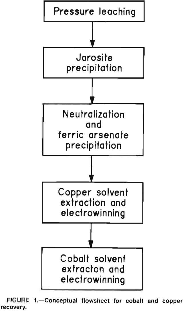
scale. The process comprises (1) oxidative pressure leaching of the flotation concentrate in an oxygen atmosphere at 195° C, (2) precipitation of the major portion of the iron and arsenic as sodium jarosite, (3) neutralization of the filtrate from jarosite precipitation to remove the last traces of iron and arsenic as ferric-arsenate precipitate, (4) recovery of copper from the iron- and arsenic-free filtrate by solvent extraction with LIX 622 and electrowinning, and (5) recovery of cobalt from the copper solvent extraction raffinate by solvent extraction witha phosphinic acid and electrowinning.
Metal analyses in aqueous solutions were determined by atomic adsorption spectrophotometry. Organic solutions were digested in nitric acid-perchloric acid to destroy the organics; the metal salts were dissolved in acid and analyzed by atomic adsorption.
Description of Feed Material
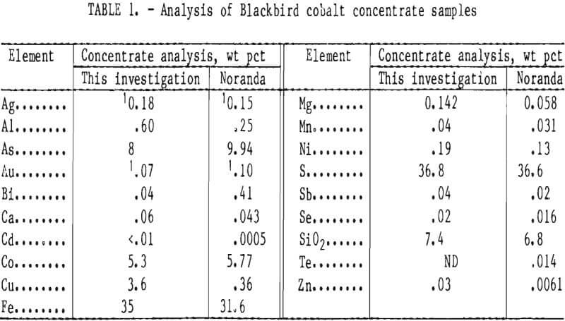
The flotation concentrate used in this investigation was provided by Noranda. Table 1 shows the chemical analysis of the concentrate. For comparison, a concentrate analysis from a report of the Noranda Research Center is also included in the table. The two concentrates were quite similar except for the higher level of chalcopyrite in the concentrate supplied to this laboratory; the difference resulted in a 10-fold higher copper concentration. The major mineral components present in both concentrates were pyrite, cobaltite, arsenopyrite, quartz, and silicate gangue minerals, with trace amounts of marcasite, magnetite, native bismuth, pyrrhotite, sphalerite, and native copper.
Oxidative Pressure Leaching
Metal values were effectively dissolved by leaching the concentrate with water at elevated temperatures under an oxygen atmosphere. Sulfuric acid, formed in situ by contacting cobaltite flotation concentrate with water at elevated temperature and pressure in an oxidizing atmosphere, effectively dissolved metal values. Table 2 shows the effect of leaching temperature on metal extraction in a 1-L Ti metal pressure reactor. Other test conditions were initial pulp density of 10 pct solids, 50-psi oxygen overpressure (oxygen pressure in excess of the saturated steam pressure at the operating temperature), and 5-h leaching time. A problem encountered at both 135° and 155° C was the formation of sulfur balls. In earlier industrial practice at the Calera mill, these sulfur balls often grew to large dimensions and caused severe mechanical difficulties. Typically, the balls contained, in weight percent, 0.36 As, 0.14 Co, 6.9 Cu, 35 Fe,
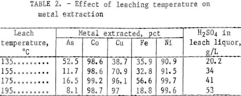
0.056 Ni, and 55.2 S. The higher proportion of copper and sulfur and the lower proportion of arsenic, cobalt, and nickel relative to the unleached concentrate indicates that these sulfur balls are derived primarily from chalcopyrite. When the leaching temperature was raised to near 195° C, an insoluble basic ferric sulfate, Fe2O3·2SO3, formed this reaction decreased both the sulfur ball formation and the iron extraction. Therefore, a 195° C leaching temperature was adopted for subsequent test work, on the high chalcopyrite concentrate. Lower leaching temperature may be preferable for concentrates containing less chalcopyrite.
The following equations represent the major chemical reactions taking place during the oxidation pressure leach:
Chalcopyrite:
4 CuFeS2 + 4 H2SO4 + 5 O2 + 2 H2O = 4 CuSO4 + 4 Fe(OH)3 + 8 S……………………………(1)
Pyrite:
4 FeS2 + 15 O2 + 2 H2O = 2 Fe2(SO4)3 + 2 H2SO4……………………………………………………..(2)
Cobaltite:
4 CoAsS + 13 O2 + 6 H2O = 4 C0SO4 + 4 H3 ASO4……………………………………………………….(3)
Arsenopyrite:
FeS2·FeAs2 + 7 O2 + 2 H2O + H2SO4 = Fe2(SO4)3 + 2 H3AsO4……………………………………(4)
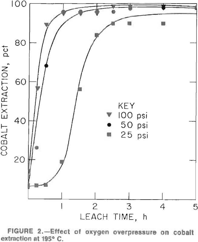
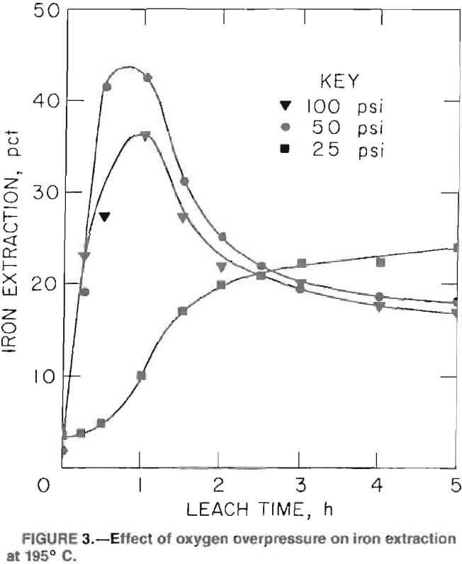
Figures 2 and 3 show the effect of oxygen overpressure on the rates of cobalt and iron extractions at 95° C and 10 pct solids. A 100-psi oxygen overpressure produced the best combination of high cobalt extraction rates and minimal iron extraction. Maximum cobalt extraction was achieved in approximately 2 h; however, iron extraction continued to decrease slightly at leaching times up to 5 h. As a consequence, subsequent test work was conducted using a 5-h retention time.
Initial pulp densities, ranging from 10 to 30 pct solids, did not affect cobalt extraction; iron extraction increased only slightly at the higher densities. Subsequent test work was performed at the higher pulp density because more concentrated leach solutions are produced and less autoclave capacity is required.
Equipment Description
Oxidative pressure leach tests were conducted in either a 1-L Ti Parr pressure reactor or a 7.5-L (2-gal) Ti Fluitron pressure reactor. The 1-L reactor had a 10.2-cm ID and 14.0-cm depth. Heating was accomplished with an external electric heating coil. The operating procedure comprised heating the slurry to approximately 20° C below the desired operating temperature, turning off the power to the heaters, and starting the oxygen flow. The exothermic sulfating reaction increased the temperature to the desired operating temperature. Thereafter, until the reaction ceased, the temperature was maintained at the desired level by controlling the rate of oxygen flow. When the reaction ceased, the power was restored to maintain the desired temperature until the specified leach time was reached. Stirring was accomplished with a 6.4-cm-diam, six-bladed, propeller-type titanium agitator rotated at 600 rpm. The reactor was not equipped with baffles or cooling coils. The slurry charge comprised 700 mL H2O plus the amount of concentrate needed to provide the desired pulp density. A tube extending to 1.3 cm from the vessel bottom was used for introducing oxygen and for taking periodic samples. The periodic samples were collected in a closed tube and held at the same pressure as the slurry in the reactor until the sample had cooled to room temperature. The collector tube was then isolated from the reactor with a valve, and the sample was collected and filtered. Flashing was avoided by cooling the collector tube before removing it.
The 7.5-L reactor had a 14.6-cm ID and 44.5-cm depth; 1.3-cm-wide baffles reached from the top to the bottom of the vessel. The reactor was heated with an external heating coil; an internal cooling coil prevented overheating during the exothermic reaction. Oxygen was admitted through a 0.6-cm tube that extended to 3.8 cm from the bottom of the vessel. A 7. 6-cm-diam, six-bladed, turbine-type agitator operated at 1,000 rpm to stir the mixture. Normally, the reactor was charged with 3, 500 mL of water plus concentrate to form the desired pulp density.
Preparation of Leach Slurry for Metal Recovery Studies
Since it was impractical to prepare sufficient leach slurry for metal recovery studies in the small autoclave, a larger (7.5-L) reactor was used. During initial runs in the larger reactor, cobalt, copper, and nickel extractions were satisfactory, but iron and arsenic extractions were excessive at 90 and 60 pct, respectively. Test conditions were 195° C with 100-psi oxygen overpressure and 30 pct solids. The high iron and arsenic extractions were attributed to poor oxygen dispersion. Initial attempts to alleviate the problem, by increasing the oxygen overpressure to 200 psi or increasing the agitation intensity, were unsuccessful. However, oxygen dispersion improved significantly

after the baffles were removed; this allowed a vortex to form. These difficulties indicate that pilot-scale, continuous-leaching studies would be needed to optimize the reactor design.
After optimizing the 7.5-L reactor operation, several runs were conducted to prepare sufficient leach slurry for further studies. Table 3 shows the average results from several tests at 195° C, 100-psi oxygen overpressure, and 30 pct solids in the initial slurry. The final leach slurry contained 17.7 pct solids. Iron and arsenic extractions remained higher than expected from the small-scale test results; however, these results may be comparable to those of a large-scale operation.
Leach Liquor Purification and Metal Recovery
To prevent product contamination, iron and arsenic must be removed from the leach liquor prior to valuable metal recovery. Preliminary testing showed that iron could be removed by solvent extraction with alkylphosphoric acids. This approach proved impractical for the following reasons: (1) the high iron extraction, (2) the formation of a ferric-arsenate precipitate at the pH best suited for iron extraction, and (3) stripping difficulties. As an alternative, jarosite precipitation was investigated to remove the iron together with the arsenic.
Jarosite Precipitation
The formula for jarosite is MFe3(SO4)2(OH)6, where M is an alkali ion. Jarosites can be formed at low temperatures; however, the formation rate is increased significantly at temperatures near boiling. Sodium jarosite was formed in this investigation by adding Na2SO4 to the leach slurry at 95° C, adjusting the pH with milk of lime, and maintaining the pulp temperature at 95° C for the length of time shown in each test description. Forming the jarosite directly in the leach slurry, rather than in the filtrate after removal of the leach solids, was more effective and reduced the number of filtration steps required. Attempts to form the jarosite directly in the autoclave by adding Na2SO4 and lime (CaO) near the end of the leach removed iron and arsenic, but reduced the cobalt extraction to 92 pct and formed a slow filtering slurry.
Sodium Sulfate Requirements
Sodium sulfate requirements for maximum iron and arsenic removal from the leach slurry were investigated in tests using (1) the stoichiometric amount needed to react with all of the soluble iron and (2) a 40-pct excess. In both tests, the slurry was adjusted to pH 1.5 and heated 4 h at 95° C. Iron precipitation increased from 94.4 to 99.1 pct and arsenic precipitation increased from 96.6 to 99.1 pct with the excess Na2SO4. In subsequent tests, 40 pct excess Na2SO4 was used.
Effect of pH
Table 4 shows test results using various amounts of CaO to produce pH values ranging from 1.27 to 2.07. Other test conditions were 40 pct excess Na2SO4 and 4 h heatingat 95° C. Results show that precipitation at approximately pH 1.5 produced maximum iron and arsenic removal without an excess loss of valuable metals.
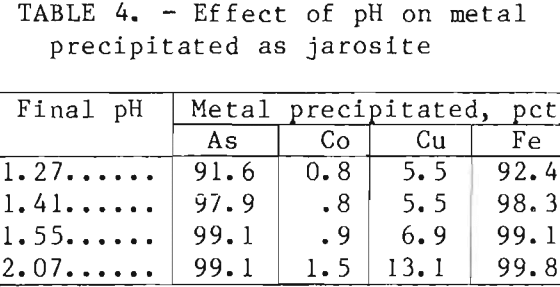
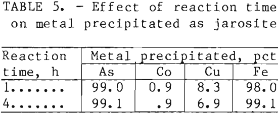
Table 5 shows the effect of reaction time at 95° C on metal precipitation using 40 pct excess Na2SO4 and a final pH of 1.5. Although both iron arsenic precipitation increased slightly as the reaction time increased from 1 to 4 h, economic considerations would probably favor the shorter reaction time.
Filtration of Jarosite Slurry
Filtration tests were conducted on a typical slurry after jarosite precipitation. A standard 0.1-ft² filter leaf with a Dynel polymer filter medium was used. All tests were conducted at 90° C using 15-in Hg vacuum. The cake was washed with water at ambient temperature. Best filtration results were achieved using a cycle consisting of 15-s filtration, 20-s cake dewatering, 27-s wash, and 13-s final dewatering. This cycle formed a 5/8-in~thick cake containing 60 pct solids. Cake washing efficiency was 99.0 pct. The filtration rate was 120 gal/(h·ft²) (of filter area), and the washing rate was 54 gal/(h·ft²). The dry solids production rate was 88 lb/(h·ft²). Based on the treatment of 100 st/d concentrate, filtration would require a 6-ft-wide belt filter operating at 17.9 ft/min with a minimum filter length of 28 ft.
Iron and Arsenic Removal from Jarosite Filtrate
A small quantity of iron and arsenic remained in the jarosite filtrate. This residual material must be removed to avoid precipitation in subsequent solvent extraction for copper and cobalt recovery. Tests were conducted on a composite batch of filtrates from several jarosite precipitation tests containing, in grams per liter, 1.25 As, 7.85 Co, 5.9 Cu, 1.95 Fe, and 0.39 Ni. The solution pH was 1.5. Iron and arsenic concentrations were higher than would normally be expected since filtrates from several nonoptimum precipitation tests were included; however, the treatment procedure would be equally applicable to liquors containing less iron and arsenic. Reagent requirements, however, may be somewhat lower when treating a more representative sample.
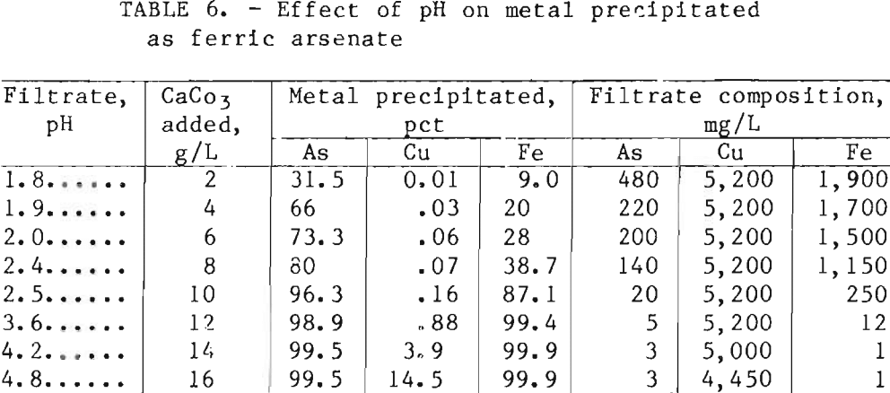
Preliminary tests showed that adequate iron rejection by ferric-arsenate precipitation required oxidation of small amounts of residual ferrous iron. Good results were achieved either by adding 1 mL of 3-pct hydrogen peroxide (H2O2 ) per liter of liquor or by sparging with oxygen for a few minutes at 75° C. After oxidation, the ferric-arsenate was precipitated by heating the solution to 60° C, adding CaCO3, mixing for 15 min, and filtering. The use of limestone (CaCO3) instead of lime (CaO) reduced the formation of gypsum agglomerates at the higher pH values. Table 6 shows the effect of final pH on metal precipitation. Addition of 15 g/L CaCO3 to increase the final pH to 4.2 resulted in maximum iron and arsenic precipitation. Copper losses increased rapidly at pH values above 4.2. Cobalt and nickel losses were less than 1 pct in all tests. Tests to determine rate of filtration were not conducted on this slurry; however, filtration was rapid. Washing with one displacement volume of water recovered over 98 pct of the soluble metals.
Figure 4 shows a proposed flowsheet and material balance for leaching 100 st/d concentrate and removing the iron and
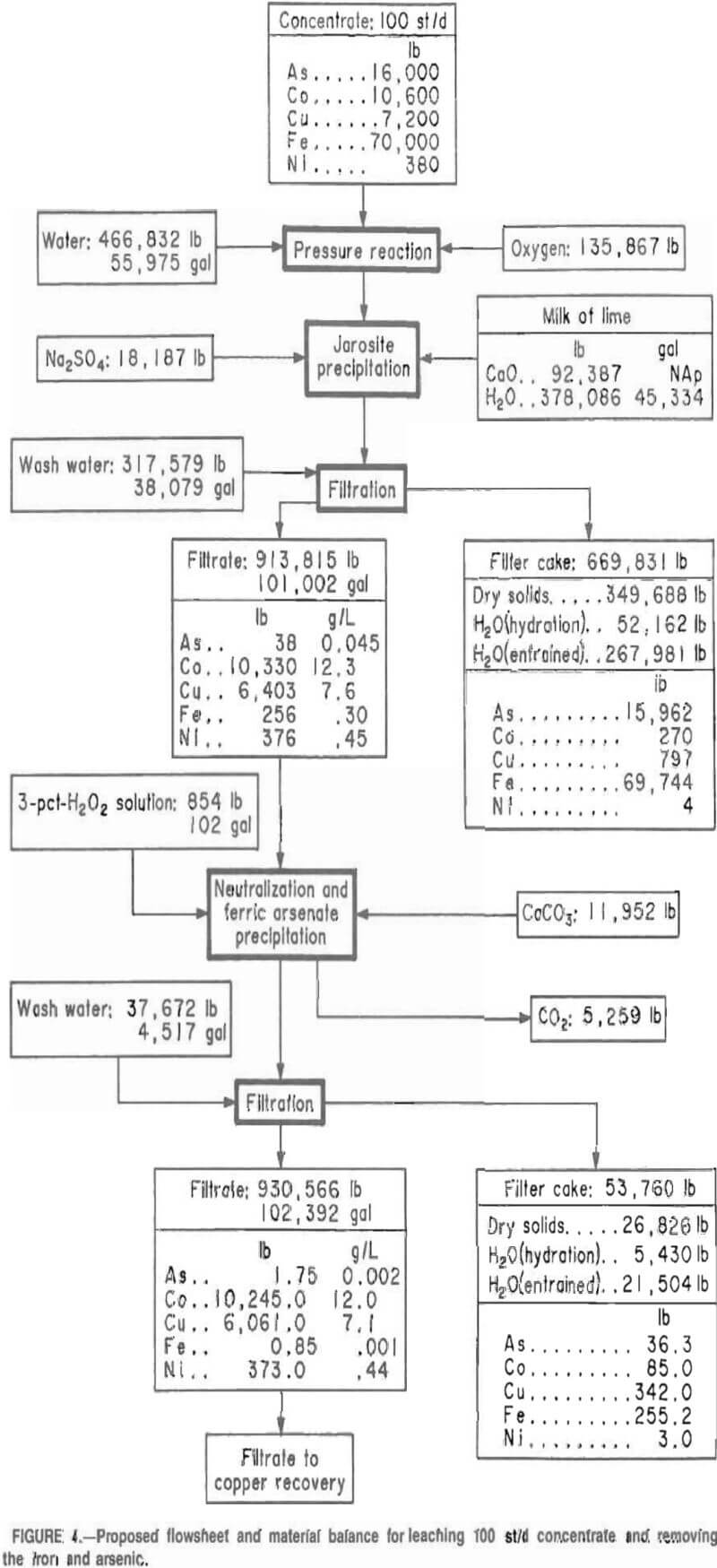
arsenic. The material balance is based on the best laboratory test results for each step of the process.
Copper Recovery
Copper in the iron and arsenic-free filtrate was recovered by a combination solvent extraction-electrowirming procedure. A hydroxyoxime-type extractant was used to recover the copper, and the stripping cell was operated in a closed circuit with the electrolytic cell. The loaded strip liquor was fed directly to the copper electrowinning cell, and the partially depleted effluent electrolyte was recycled to the stripping operation.
Solvent Selection
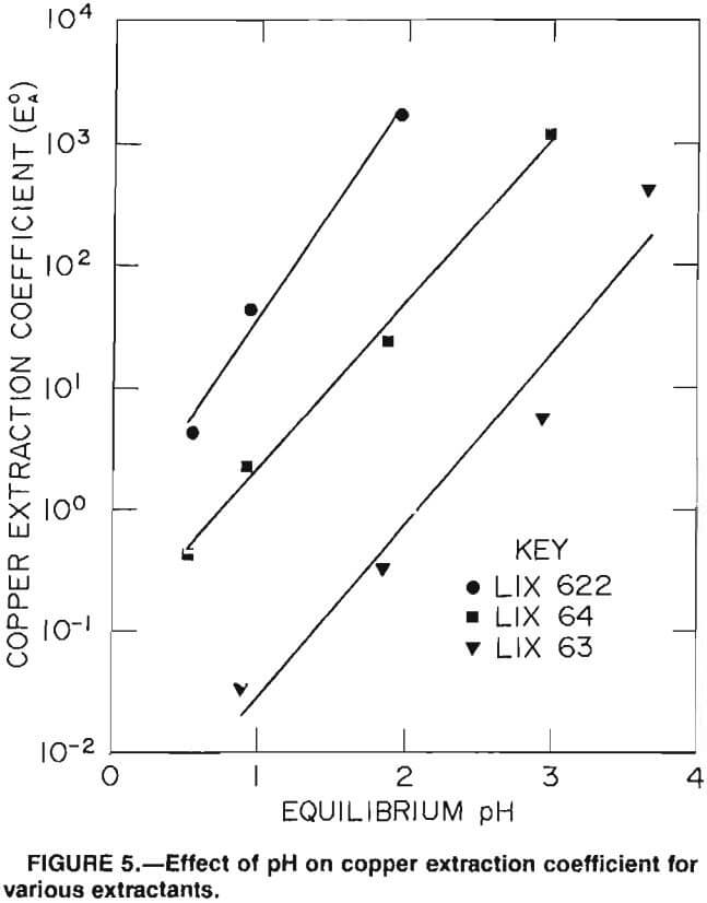
Three of the more common chelating-type copper extractants available, LIX 63, LIX 64, and LIX 622, were tested for effectiveness in continuous countercurrent testing. The most effective, LIX 622, had the highest extraction coefficient at the lower pH values. Copper extraction coefficients were obtained by equilibrating equal volumes of 20-vol-pct extractant dissolved in kerosene with copper-sulfate solution containing 6 g/L Cu at various pH values. The pH was adjusted by adding concentrated H2SO4 or NH4OH as required. At pH 3, the loading for LIX 622, LIX 63, and LIX 64 were 13.4, 15.0, and 7.3 g/L Cu, respectively. Test results, shown in figure 5, indicate that LIX 622 is the most effective extractant at the lower pH values; consequently, it was selected for further studies.
pH Control
The following equation describes the extraction of copper by hydroxyoximes:
(2 R-H)org + (Cu²+ + SO4= )aq = (R2Cu)org + (2H+ + SO4= )aq…………………………………(5)
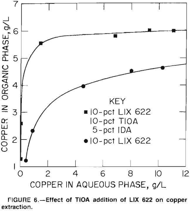
This equation shows that each equivalent of copper extracted forms an equivalent of H2SO4, which reduces the aqueous pH. Since copper extraction decreases with decreasing pH, complete removal of copper from a concentrated solution requires neutralization of some of the free acid formed. For example, three-stage countercurrent extraction of pH 3.3 sulfate solution containing 12 g/L Cu with 10-pct LIX 622 reduced the aqueous pH to 0.6 and left 0.5 g/L Cu in the reaffinate. This result made it obvious that some form of pH control would be required to achieve complete copper removal. Since free amines absorb H2SO4, screening tests were performed to determine whether a mixture of LIX 622 and triiscoctylamine (TIOA) would maintain the pH high enough to allow complete copper extraction. Figure 6 shows the distribution isotherms for copper extraction from 12 g/L Cu feed with (1) 10-pct LIX 622 solution, and (2) with 10-pct LIX 622, 10-pct TIOA, and 5-pct isodecanol (IDA) in kerosene. Isodecanol was added to prevent third-phase formation during subsequent Na2CO3 treatment of the extractant to reconvert it to the free-base form. Test results show that the mixed extractant had a higher capacity for copper and also reduced the copper concentration in the aqueous phase.
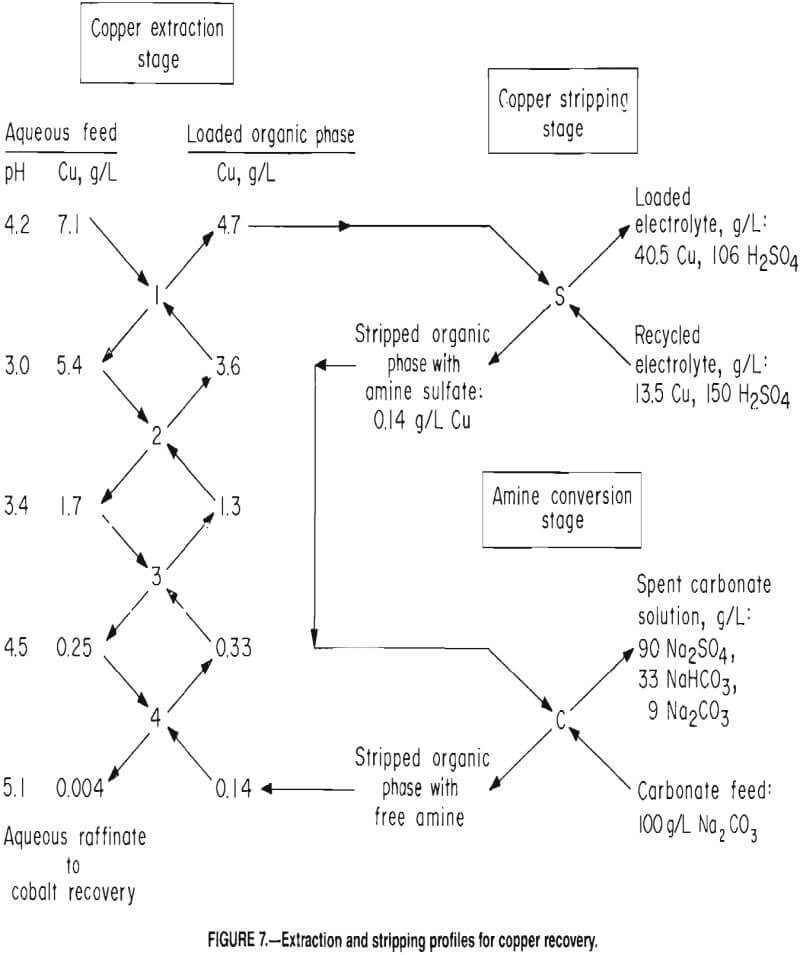
Continuous Countercurrent Solvent Extraction
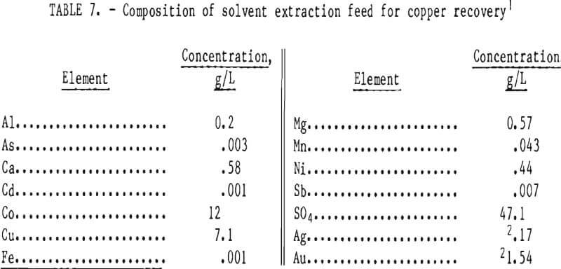
Continuous countercurrent solvent extraction tests were conducted using feed solution with the chemical composition
shown in table 7. Tests were performed in separate, interconnected 2.25-in-ID mixer-settlers. The effective mixer and settler volumes were 160 and 430 mL, respectively. Agitation (about 1,000 rpm) was provided with a 2. 5-cm-diam turbine with four straight blades. The best extraction conditions included four stages, an organic phase flow rate of 6 mL/min, and an aqueous phase flow rate of 4 mL/min. These conditions produced an organic-to-aqueous flow ratio of 1.5 and a 16-min nominal retention time in each mixer. Stripping was accomplished in a single stage using electrolyte recycled
from the copper electrowinning cell. The strip liquor flow rate was 1. 1 mL/min. Amine sulfate in the stripped organic solution was converted to free amine by single-stage contact with a 10-pct Na2CO3 solution. The solution was fed to the mixer by demand from a pH controller set to maintain pH 8 in the mixer.
Figure 7 shows the extraction profile for a typical test. Copper reduction to 4 ppm resulted in a Co-Cu ratio of over 3,000 in the raffinate. Raffinate containing 11.5 g/L Co served as feed to the cobalt recovery circuit. Approximately 3 pct of the cobalt and nickel were coextracted with the copper. A loaded organic phase containing, in grams per liter, 0.29 Co, 0.08 Ni, and 0. 003 Zn in addition to the copper was produced. The loaded strip liquor contained, in grams per liter, 1.1 Co, 0.05 Ni, and 0.02 Zn in addition to the copper. Additional testing would be required to determine the maximum permissible buildup of cobalt and nickel concentrations in the electrolyte to produce acceptable copper cathodes.
Copper Electrowinning
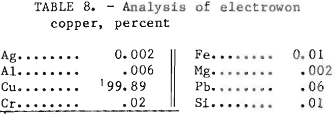
Copper was electrowon from the loaded strip liquor in a plastic cell 12. 7 cm long by 8.9 cm wide by 14.0 cm deep. The cell contained three lead anodes, each 7.6 cm wide by 0.16 cm (1/16 in) thick, and two copper starting sheets, each 7.6 cm wide by 0.08 cm (1/32 in) thick, that were immersed to a depth of 7.6 cm in the electrolyte. The spacing between the anodes and cathodes was 1.3 cm. The electrolyte contained a free sulfuric acid concentration of 150 g/L. The cell was operated at room temperature with a current density of 7.3 A/ft² of cathode area. Most tests were run for 7 h at each specified set of conditions. Copper
was reduced from 40.5 to 13.5 g/L in the electrolyte as it passed through the cell. Table 8 shows the spectrographic analysis of a typical deposit. Copper analysis was determined by difference.
Figure 8 shows the proposed copper solvent extraction and electrowinning flowsheet and material balance for the treatment of the iron- and arsenic-free filtrate produced from leaching 100 st/d concentrate; the flowsheet and material balance are projected from the best laboratory test results. Table 9 shows the estimated reagent requirements to recover
1 lb Cu. Organic losses were based on estimated entrainment of 0.5 gal solvent in every 1, 000 gal of total aqueous flow (raffinate, strip liquor, and Na2CO3 solution) through the system. Since
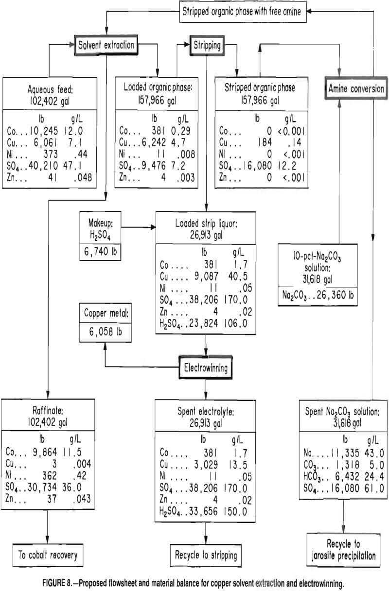
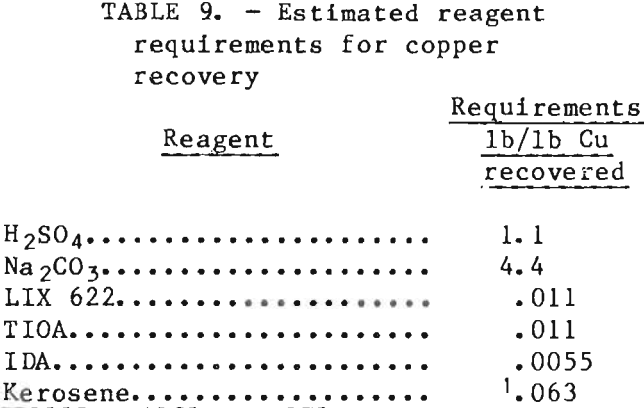
conversion of the amine sulfate to free amine with Na2CO3 forms a Na2SO4 solution that probably could be recycled to the jarosite precipitation step, a credit could be allowed for this Na2SO4.
Cobalt Recovery
Cobalt in the copper solvent extraction raffinate was recovered by (1) solvent extraction with Cyanex 272 (an alkyl phosphinic acid-type extractant), (2) stripping the loaded extract with electrolyte recycled from the cobalt electrowinning cell, and (3) returning the loaded strip liquor to the electrowinning cell for cobalt recovery. No attempt was made to recover the low concentration of nickel in the copper solvent extraction raffinate. Since the only contaminant added to the aqueous solution was sodium, the levels of other contaminants were low, and the pH was near 7, the cobalt solvent extraction raffinate could be disposed of in an existing natural stream.
Solvent Selection
Organophosphorus acids were considered to be the most promising family of reagents for cobalt recovery from the copper extraction raffinate. Commercially available organophosphorus acids include phosphoric, phosphonic, and phosphinic acids. The following diagrams show the structure of the three types.
Work reported by Preston indicated that the cobalt-nickel separation under comparable conditions increases in the

order phosphoric < phosphonic < phosphinic acid. This order of selectivity was confirmed in tests using sulfate solutions. Consequently, a phosphinic acid type extractant, Cyanex272, was selected for continuous countercurrent tests to recover cobalt.
Continuous Countercurrent Solvent Extraction
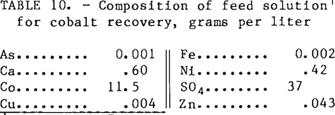
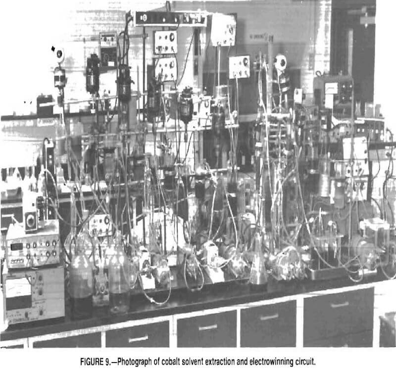
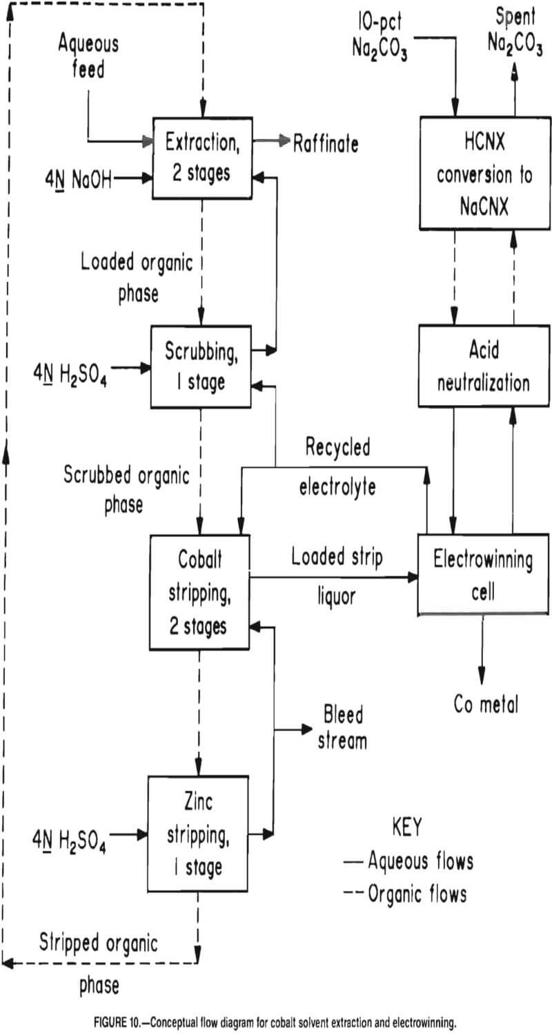
Continuous countercurrent solvent extraction tests were conducted using copper solvent extraction raffinate with the chemical composition shown in table 10. The organic extractant was unmodified 0. 514 Cyanex 272 extractant dissolved in kerosene. Tests were performed in separate, interconnected mixer-settlers with the same dimensions as those used for copper solvent extraction. Figure 9 is a photograph of the cobalt solvent extraction and electrowinning circuit. Agitation (about 1, 000 rpm) was provided with flat, 2. 5-cm-diam, four-bladed paddles. The extraction circuit, shown in simplified form in figure 10, comprised two extraction stages, one scrubbing stage, two low-acid cobalt stripping stages, and one high-acid zinc stripping stage. Additionally, a two-unit mixer-settler system was operated in closed circuit
with the electrolytic cell to control the pH of the electrolyte. The recirculating electrolyte stream was contacted with the sodium form of Cyanex 272 extractant in the first mixer-settler, and the adjusted electrolyte was returned to the electrolytic cell. The acidified Cyanex 272 extractant was converted back to the sodium form by contacting it with a Na2CO3 solution in the second mixer-settler unit. The aqueous and organic flow rates in the extraction circuit were 3.1 and 7.2 mL/min, respectively, producing an organic-to-aqueous flow ratio of 2.3 with approximately 15-min nominal retention time per stage. Retention time in the stripping stages was approximately the same.
Selenium has been reported to be a troublesome element that contaminates the final cobalt product. The solutions treated in this investigation did not have any detectable selenium; however, in one test, the feed solution to the cobalt solvent extraction circuit was spiked to 0.036 g/L Se with sodium selenate. This selenium did not extract, and the cobalt metal did not contain any detectable selenium.
Cobalt Extraction
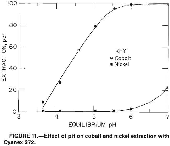
Results of batch tests to determine the pH effect on nickel and cobalt extraction with 0„5M Cyanex 272 extractant indicate that the preferred pH range for minimum nickel extraction with maximum cobalt extraction is 5.0 to 5.9 (fig. 11). To maintain the desired pH, hydrogen ions released by the cobalt-hydrogen exchange reaction were neutralized by adding 4N NaOH solution to the mixers as needed. Sodium hydroxide was preferred over Na2CO3 because it minimized phase separation problems. Standard combination pH electrodes immersed in the mixed phases measured the pH accurately as long as the aqueous phase was continuous. The NaOH solution was pumped to the mixers when signaled by pH controllers. Over 99 pct of the cobalt was extracted by maintaining pH values of 5.9 in the raffinate stage and 5.0 in the loaded organic stage. The pH in the raffinate stage was maintained at 5.9 to assure maximum cobalt extraction and at 5.0 in the loaded organic stage to minimize nickel extraction.
Nickel Rejection
Although some nickel coextracted with cobalt in two extraction stages, the addition of a scrubber stage displaced most of the coextracted nickel. The scrubber stage used recycled electrolyte containing 28 g/L Co, which was maintained at approximately pH 3 by the addition of 4N H2SO4. The volume of electrolyte recycled to the scrubber was equal to the volume of acid fed to the high-acid stripper less the bleed-stream volume. This insured that the total volume of electrolyte in the system remained constant. Overall, less than 0.5 pct of the nickel in the feed appeared in the electrowon cobalt metal.
Zinc Rejection
Zinc is completely extracted by Cyanex 272 at pH 3; consequently, any zinc In the aqueous feed to the cobalt extraction circuit is coextracted with cobalt. Investigations showed that by maintaining a pH of 1.5 to 2.0 in the second cobalt-stripping stage, nearly all of the cobalt and virtually none of the zinc was stripped. Strong acid from the zinc-stripping stage was used to adjust the pH in the second cobalt strip stage; this acid was replaced with fresh 4N H2SO4 (fig. 10). The high-acid strength in this stage effectively stripped, the zinc. A small bleed stream of strong acid from the zinc-stripping stage is required to prevent zinc buildup in the circuit. In this work, the zinc was allowed to build up to 1 g/L with no ad-verse effect. Further testing would be required to determine the maximum zinc concentration that could be tolerated.
Cobalt Electrowinning
Loaded strip liquor containing 36.5 g/L Co was pumped through a bed of activated carbon to remove any entrained organic extractant and then into an electrowinning cell. The electrolytic cell had the same dimensions and configuration as the cell described in the copper electrowinning section. The cell had two lead- antimony (4 pct Sb) anodes 7.6 cm wide and 0.16 cm thick. The single cathode was 0.08-cm-thick type 316 stainless steel with the same other dimensions as the anode. The electrodes were immersed to a depth of 9.0 cm in the electrolyte. The surface of the cathode was roughened on an emery wheel to improve cobalt adherence. The anodes were wrapped with canvas bags to prevent the transport of impurities or oxidized cobalt particles from the anodes to the cathode. The cell was operated at pH 2.5 and 50° C, with a current density of 15 A/ft² (of cathode area). Under these conditions, current efficiency ranged from 92 to 95 pct. The electrolyte was recirculated through a mixer-settler and contacted with the sodium form of Cyanex 272. This process effectively neutralized the excess acid. Electrolyte dilution, which would have occurred with the addition of a basic solution, was also avoided. The organic flow was regulated by a pH controller set to maintain pH 2. 5 in the mixer. The Cyanex 272 extractant in the hydrogen form was converted back to the sodium form by contact with a 10—pct-Na2CO3 solution in another mixer settler. Sodium carbonate flow was regulated by a pH controller set to maintain pH 8 in the conversion mixer. Sodium sulfate buildup in the electrolyte was controlled by cooling and crystallizing after saturation had been reached at 50° C.
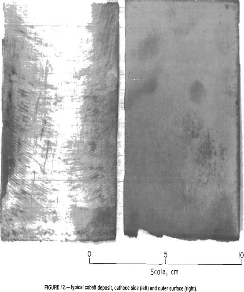
Figure 12 is a photograph of a typical cobalt deposit. The metal had a shiny appearance on the cathode side and a dull metallic luster on the outer surface. The deposit stripped easily from the stainless steel cathode. Table 11 shows a typical deposit composition using Inductively Coupled Plasma (ICP) analysis for impurities and determining cobalt by difference.
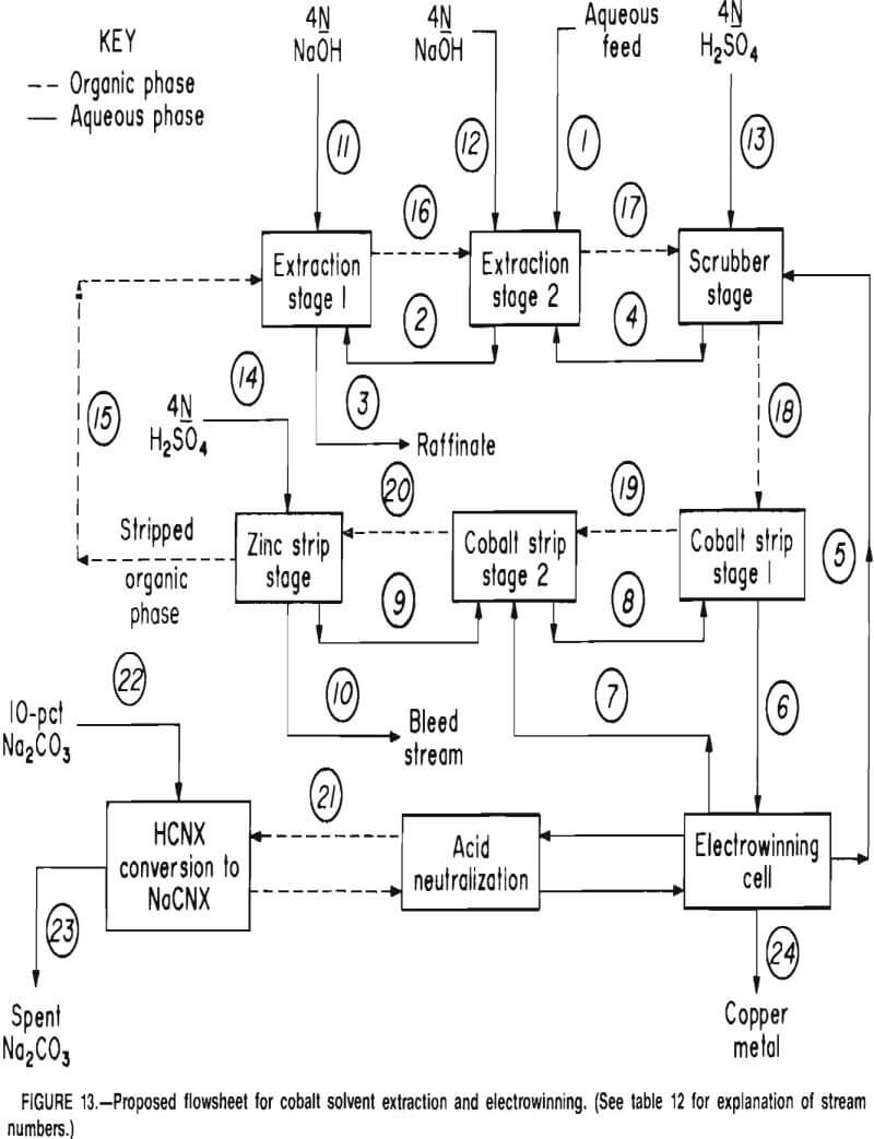
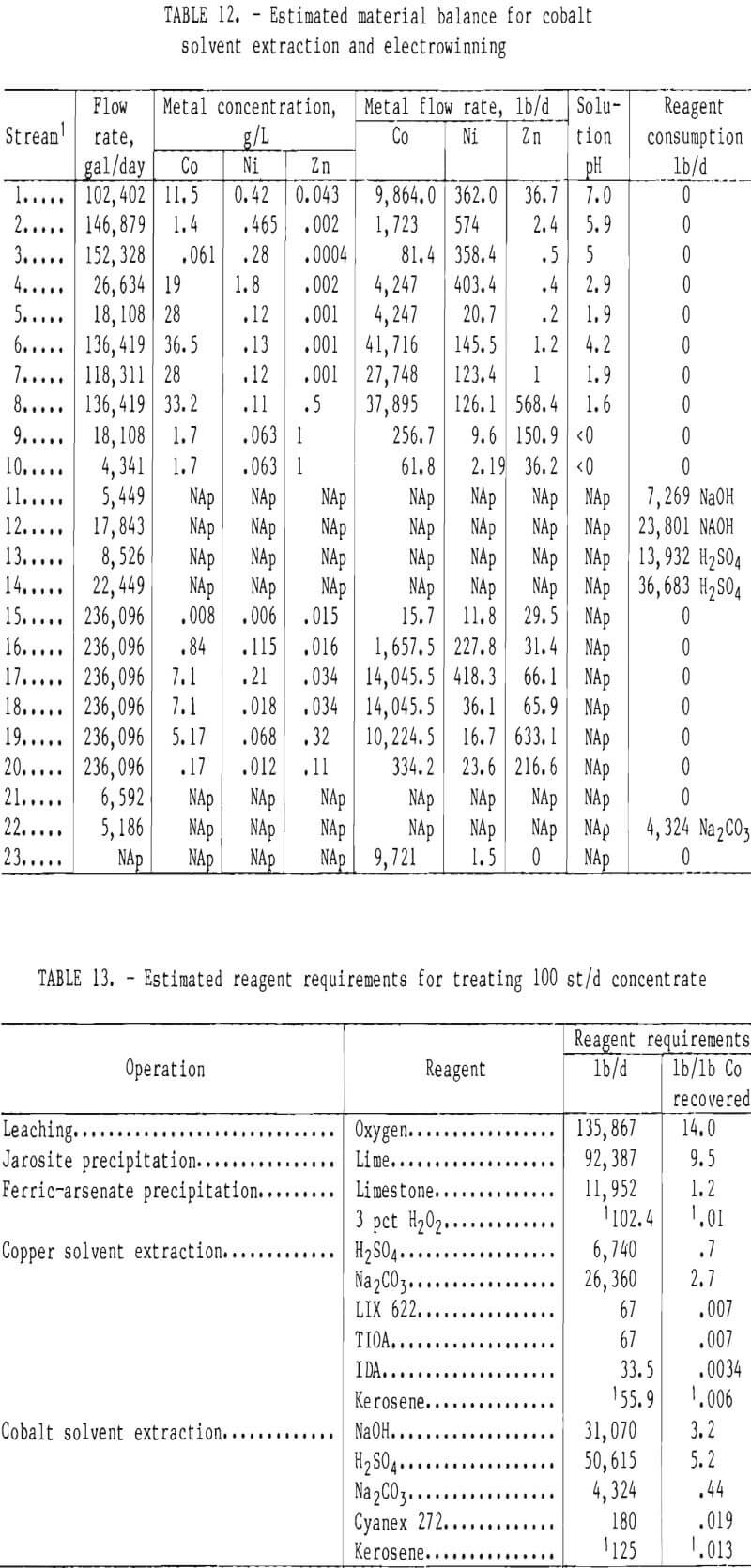
Figure 13 is a proposed flowsheet, and table 12 shows the corresponding estimated material balance for cobalt

recovery from copper solvent extraction raffinate; the flowsheet and material balance are projected from laboratory results. Material balances are based on the estimated daily volume of solution produced during operation of a plant treating 100 st/d of concentrate. The spent sodium carbonate-sodium sulfate solution from HCNX conversion to the sodium form could probably be recycled to jarosite precipitation. However, a more extensive pilot operation would be needed to determine whether the recycled sodium sulfate solution would present any serious problems. Before discharge to existing natural streams, the bleed stream and raffinate from cobalt extraction may require further treatment such as (1) solvent extraction with Cyanex 272 extractant at a higher pH, or (2) precipitation to remove and possibly recover the small amount of nickel.
Summary of Reagent Requirements
Table 13 shows the estimated reagent requirements based on laboratory testing for treating 100 st/d of concentrate to produce 6,058 lb Cu and 9,721 lb Co. Reagent requirements are expressed in pounds per day and pounds per pound of cobalt recovered. Sodium sulfate needed to form jarosite is not included because sufficient Na2SO4 is produced in the solvent extraction operations to fulfill this need. Organic extractant requirements are based on estimated entrainment of 0.5 gal extractant per 1,000 gal of total aqueous flow through the solvent extraction system.
Future Research
This laboratory-scale investigation demonstrated the feasibility of using a combination precipitation-solvent extraction approach to the recovery of cobalt, copper, and possibly nickel from a cobaltite flotation concentrate. However, there are certain areas of research that need further exploration to determine the relative merits of this process as compared with those of other proposed processes. Future investigation should include the following research:
Pilot-scale investigations should be conducted using a continuous feed reactor because it was difficult to duplicate results when scaling up from a 1~L to a 7.5-L batch reactor.
The cobalt solvent extraction with its many recirculating streams should be run longer at steady-state conditions to determine whether any buildup of impurities in these streams would cause serious problems.
More work is needed to determine what treatment, if any, is needed to prepare the various effluent streams for discharge to existing natural streams.
The disposition of the gold and silver should be determined and procedures developed to recover these precious metals. Based on an estimated 90~pct recovery, annual gold and silver production would be 2,500 and 5,800 tr oz per year, respectively.
A comparison of economic evaluations for both the precipitation-solvent ex¬traction process described in this report and the process described by Harris, Monette, and Stanley, should be made to determine the most economical.
Conclusions
The objective of devising an alternative process for recovering cobalt and copper from sulfate liquors by liquid extraction rather than precipitation was achieved. Over 91 pct of the cobalt and 84 pct of the copper were recovered from cobaltite concentrate by a process that involved (1) oxidative pressure leaching, (2) jarosite precipitation, (3) ferric-arsenate precipitation, (4) selective solvent extraction of copper with a mixed hydroxyomine-amine extractant, (5) electrowinning of copper from recirculating acidic strip liquor, (6) selective solvent extraction of cobalt from copper solvent extraction raffinate with an alkyl phosphinic acid extractant, and (7) electrowinning cobalt from recirculating weak acidic strip liquor. The electrowon copper was 99.89 pct pure, and the electrowon cobalt was 99.8 pct pure. An economic evaluation remains to be performed.
