
There was a continual increase in ball mill lubrication oil consumption. However, visual inspections could not confirm the presence of a trunnion oil seal leak. By the end of month it was assumed that the only possible place for this leak was at the outboard discharge trunnion seal so that oil was leaking into the slurry discharge pump. A maintenance schedule was developed to replace the discharge trunnion deals. When the discharge trommel was removed the maintenance supervisor noticed that the trunnion liner dropped down and that slurry and small grinding balls came out of the trunnion cavity. Since this cavity was designed to be free of all substances the presence of slurry could only be explained by a failure of the metal to metal seal of the trunnion liner. (See Figure 1.)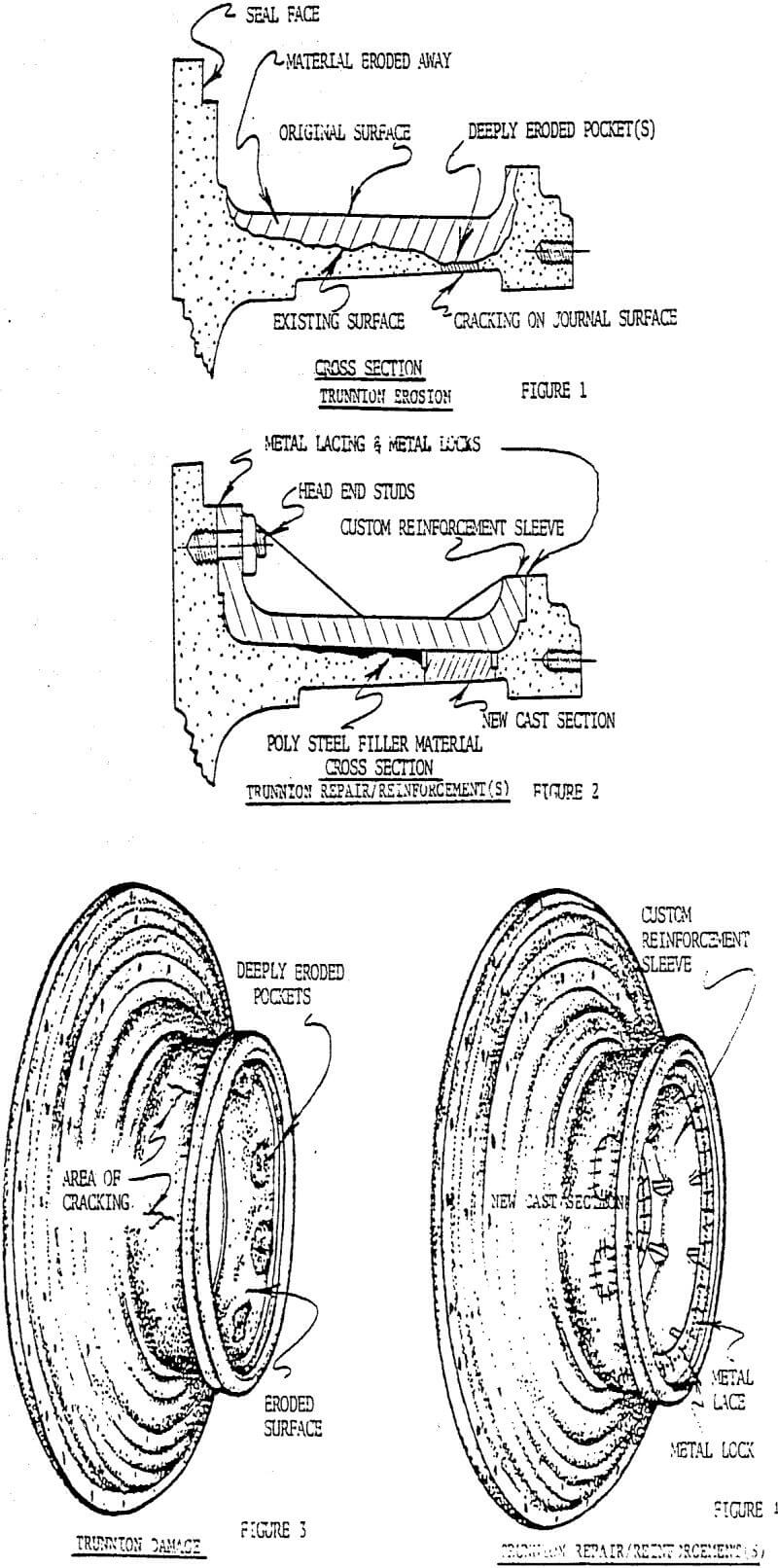
When the trunnion liner was removed there was evidence of slurry racing which had scalloped out areas of the mehanite mill end casting. Also two cracks were found, each about one inch long, that extended through to the journal surface. These cracks were drilled at their end to try to reduce their spreading. Steel patches were welded onto the head casting and the pocket was filled with a castable epoxy to try to reduce oil loss. The trunnion seal area was filled with silicone sealant to try to fill the severely eroded metal to metal trunnion seal area. The mill was placed back on line about 30 hours later.
Oil consumption continued during the next week so a 1.27cm thick x 25.4cm wide (½ inch thick x 10 inch wide) band was rolled and bolt spread into position to hold the initial plates and more castable epoxy in place. The trunnion cavity was then filled with two part urethane tire fill to prevent any further ingress of slurry into the trunnion cavity.
The mill oil consumption continued at a slightly reduced rate and numerous mill shutdowns were taken to visually inspect the journal surface for crack propogation or the existence of new cracks. A new mill discharge head was ordered with a 16 week delivery.
During an inspection another crack was observed in approximately the same location as the two originals. This crack also exhibited some metal displacement 0.025cm (say 0.010 inch) cowards the journal bushing.
The existence of the third crack led the insurance company to bring experts to view the problem and help decide if other temporary repairs could be made to insure the continued operation of the mill until the new mill head was received and installed.
XYZ has a world-wide reputation for the repair of rotating machinery such as compressors. They had not attempted the repair of a ball mill prior to this mill although they had repaired cracks in a rotating kiln head of similar size.
After inspection of the outer trunnion area ems proposed a two phase repair. Phase 1 would entail cutting out the existing cracks and severely scalloped wear areas followed by the insertion of patches which were to be (metal locked) and (metal laced) in place.
Phase 2 was a much more involved procedure of inserting a fabricated insert in the trunnion cavity to strengthen the trunnion. Phase 2 would be required if too much metal had eroded from the trunnion to provide a high enough safety factor for the insurance company to keep the “loss of production” insurance policy in effect.
The ball mill was shut down on June 28 for removal of the trunnion, liner and two part urethane. The presence of the urethane extended the job from the original six hours to 4 days.
Preliminary discussions between engineers indicated that there were possibly as many as six (6) eroded areas that would be susceptible to cracking based on their visual comparison of eroded areas during their initial repair attempts.
Because of the geometry of the bearing pedestal, only the amount of erosion in the upper half of the trunnion could be accurately measured. What these measurements revealed was that a lot more of the parent material had been eroded than had been expected. The measurements indicated that under the inboard trunnion surface erosion had removed approximately 7.62cm (three inches (3″)) of parent material. Where there should have been 12.7cm (five inches (5″)) of mehanite cast iron there now averaged approximately 5.08 cm (two inches (2″)) of material. Under the outboard trunnion surface (where the cracking was occurring) the parent material had eroded to an average thickness of less than 2.54cm (one inch (1″)). The major scalloped out areas occurred in this area around the circumference of the trunnion. These areas were as thin as 0.318cm (one-eighth of an inch (1/8″)). The newest crack found had started in an area that was approximately 0.953cm (three-eighths of an inch (3/8″)) thick.
After the actual extent of the erosion had been measured and the limited amount of wall thickness in the repair area had been found, it was determined the reinforcement phase of the repair would be required in conjunction with the repair phase, ems designed an internal, flanged sleeve to provide this reinforcement.
As stated earlier the areas in the lower half of the trunnion could only be approximated because of the geometry of the bearing housing. However, based on these estimations ems determined that a total of eight (8) to nine (9) areas would have to be repaired. The number was in determinant at the time because of the proximity of two of the scalloped out areas to each other. Design criteria had been established regarding how close sections could be installed to each other and until the mill could be rotated one hundred and eighty degrees accurate measurements of the lower half would have to wait.
Design Considerations
The design considerations of our repairs were to replace or exceed the original strength of the trunnion in the areas affected by the erosion and to eliminate lubrication oil leakage. In achieving these objectives, we maintained complete compatibility of the materials and reclaimed, as necessary, affected elevations and dimensions to O.E.M. standards. Our evaluation of the stresses include shear at critical planes bending moments compressive hoop loading, and hydrostatic pressure. These allowables and calculations of the affected cross-sectional areas dictated the minimum repair design limits to be achieved.
The above criteria dictated that the approximate minimum thickness of the trunnion where a section could be installed would be 1.905cm (three-quarters of an inch (¾”)) and the approximate minimum spacing between any two sections should be greater than 7.62cm (three inches (3″)).
Repairs Performed
With the design criteria established the following repair/reinforcement procedures were performed. Initially the mill was jacked-up to remove the weight of the mill and the charge from the trunnion. The sections in the upper half of the trunnion that either exhibited cracking or were less than 1.905cm (.75″) thick were removed. There were four (4) excavations required in the upper half with approximate sizes of 16.193cm (6.375″) x 28.895cm (11.375″) to 14.288cm (5.625″) x 20.472cm (8.06″). Sections of upgraded cast iron were then fitted into these excavations and attached utilizing metal lock and metal lace repair techniques. After the installation of these sections was completed, the surfaces of the sections were machined and ground back to the original elevation, contour and finish of the trunnion surface. The machining of the surface of the trunnion was accomplished utilizing a grinding fixture custom designed and manufactured specifically for this particular project by ems.
The mill was then lowered and the mill was rotated 180 degrees to expose the lower section of the mill. The depths of the scallops in the lower section were determined. The results of these measurements indicated that four sections would have to be installed in this half of the trunnion also. The four sections were of the same approximate dimensions as those mentioned above.