
Invented and first put into use, a “new and useful improvement in rotary ore roasting furnaces,” which was intended “to increase the capacity, effectiveness and working economies of such furnaces.” The following description and accompanying figures are taken from the patent papers:
Fig. 1 is a side elevation of the feed-end of the Howell rotary furnace, with parts broken away, the better to exhibit my invention. Fig. 2 is an end elevation of the same. Fig. 3 is an end elevation of the same, showing a modification of my invention.
In operating a furnace of this kind, of the capacity of one ton of ore an hour, it was found that for the best work the two fire-places (one at each end of the revolving cylinder) consumed about ten cords of wood every twenty-four hours, and that about twenty-four tons of silver-ore were introduced through the feed-pipe. It was also found that of the amount of ore, fully one-third did not go through the revolving cylinder, but went into the dust-chambers about the feed-end of the furnace or cylinder, and this ore going into the dust-chambers was found not to be sufficiently chloridized for amalgamation, but had to be re-roasted. I then caused to be made, out of boiler-plate iron, a segment of a circle, the height of which was about one- third of the diameter of the cylinder or furnace, the circumference of the circle being smaller than the circumference of the furnace, so that about a half-inch space would be left between the plate and the furnace, when said plate or segment was in position. This segment or plate of iron was then fastened to the bottom of the feed-pipe, as shown in the drawings, wherein A represents the revolving cylinder or furnace; B, the fire-place and dust-chambers at the feed-end of said furnace; C, the inclined feed-pipe, and D, the diaphragm, partition, or plate fixed within said furnace, A. With the diaphragm or plate, D, in the position shown, the furnace was run for about a month, and it was found that with the furnace in best working condition only four cords of wood every twenty-four hours were consumed, that no fire was required at the feed-end of the furnace, that not one-twelfth of the ore passed into the dust-chambers, and that the chloritization of the ore was more complete than ever before. The advantages of this device are, that when the
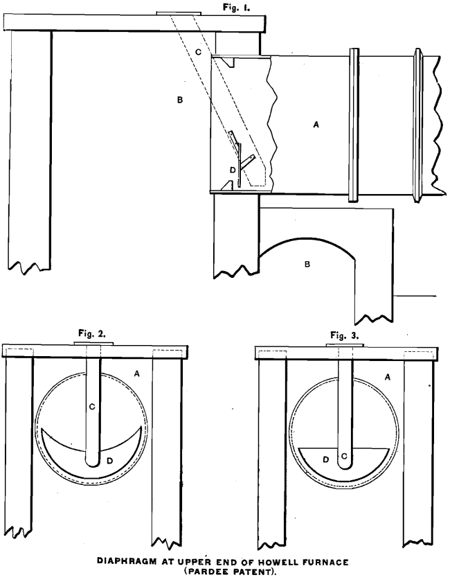 diaphragm or plate, D, is placed in position with the furnace, A, the cold crushed ore introduced through the feed- pipe, C, drops into an eddy in the cylinder, and is not for some time exposed to the flame and draft, said flame and draft being directed towards the upper part of the furnace, A, by the said diaphragm, D. The said crushed ore, therefore, has time to become heated, and its particles to become aggregated before it is carried up high enough by the rotary movement of the furnace to drop through the moving current of flame and air, so that the danger of being carried by the draft into the dust-chambers is avoided. By the use of this diaphragm, D, the auxiliary fire for roasting the air-floated crushed ore is also dispensed with, as the heat and products of the combustion from the main fire-box are retained longer and made more effective in the furnace. Consequently, the expense of building and attending to an auxiliary fire-chamber is avoided. This diaphragm, D, also prevents, as has been set forth, the making of an excess of flue- dust, not more than one-tenth or one-twelfth of the amount of ore passing through the furnace, thus preventing what has hitherto been a great expense and loss in the working of ore-roasting furnaces. This diaphragm, D, may be constructed of wrought- or cast-iron, and may be made in several forms, as a segment of a circle, as shown in Fig. 3; as a lune, as shown in Fig. 2, or in other convenient form. It can be fastened to the feed-pipe, C, as shown in Fig. 1, or to a suitable iron frame, and be suspended from above, and be braced and held in the desired position by suitable braces, and can be arranged to be raised or lowered by suitable devices.
I claim as new and desire to secure by letters patent, the combination with the rotary furnace, A, and feed-pipe, C, of the diaphragm or partition, D, substantially as herein shown and described
A Howell furnace, with the Pardee patent diaphragm, has been used for several years by the Moulton Mining Company at Butte, and has given good results.
Fig. 4 is a side elevation of a well-known form of furnace with my improvements attached thereto, parts being broken away more fully to illustrate my invention. Fig. 5 is a view in detail of my improvements. In the well-known Oxland furnace an annular piece has been secured on the outside upper end of the cylinder and provided with a short tubular piece or pipe secured to the annular piece and projecting outwardly, or away from the cylinder. A crescent-shaped plate, or a plate of the form of a segment of a circle, has also been secured to the feed-pipe at the upper end of the cylinder on the lower side. In both of these instances the fine dust of the ore is not chloridized before it reaches the draft-line in the rotary cylinder, and much of it is carried out through the dust chambers unroasted, and is lost. To obviate these difficulties, as well as to dispense with the fire at the upper end of the cylinder, is the object of my invention.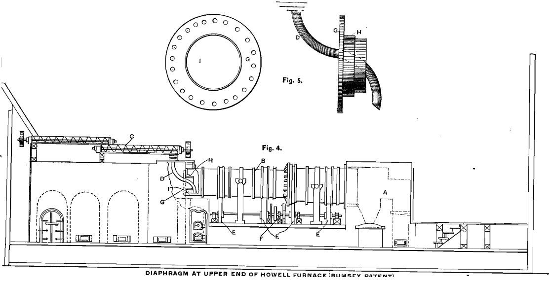
Referring to the drawings, in which like letters of reference indicate corresponding parts, my improvement is shown as applied to the well-known Brueckner or Howell furnace. A is the fire-chamber; B, the rotary cylinder, and C, the mechanism for feeding the pulverized ore. D is a tube or pipe with a funnel-shaped mouth for conveying the ore into the upper end of the cylinder. The cylinder is rotated by friction-wheels, E, and the driving shaft and gearing, F, or in any other suitable or known manner. The structure just referred to is well known and need not be further described in detail. To the upper end of the cylinder I secure a flanged annular piece, G, which is constructed of metal of the proper thickness, and is bolted, riveted, or otherwise secured, to the end of the cylinder. This ring-like piece, G, has an inwardly-projecting annular flange or tubular portion, H, thus forming on the inside upper end of the cylinder an annular chamber, I, which, being out of the draft-line of the cylinder, receives and holds the fine dust of the ore until it is roasted or chloridized, when, as before stated, it falls by gravity to the bottom, and is discharged with the heavier portions of the ore into the pulp-bin or receiver.
It will be seen that the feed-pipe is placed diagonally across the opening in the annular piece, G, and that it delivers the pulverized ore or pulp at the bottom of the cylinder. I prefer to construct this feed-pipe as shown in the drawings—viz.: somewhat curved, and with its lower end partly cut away, or with a section removed therefrom, as at A, on the side next the chamber, I. The object of this construction is to deliver the pulverized or stamped ore, or the bulk of it at least, into the chamber, I, instead of into the body of the cylinder, so that it will not fall to the lower end and pass out until it is thoroughly roasted.
The feed-pipe may be round, square, or of any desired form. I prefer to have the inwardly-projecting flange portion, H, about twelve inches in length in a sixty-inch cylinder, but I do not restrict myself to these proportions. The flange is preferably so located that it forms a chamber about one half of the area of the cylinder.
It will be seen by my improvement, that I am able to deliver into the cylinder and hold the lighter and finer particles of the dust of the ore out of the draft-line thereof until they are roasted or chloridized, and it will be found that all dust going into the flue-chambers will be chloridized as high as, or higher than, that passing through the cylinder.
My invention also does away wholly with the use of an auxiliary fire at the small end of the furnace, and also decreases largely the amount of fuel used in the principal furnace at the lower end of the cylinder. Having thus fully described my improvement, what I claim as new, and desire to secure by letters patent, is:
- A rotary furnace for roasting or chloridizing ores, provided at its upper or receiving end with closed internal annular chamber, to receive and retain the dust-particles of the ore until they are chloridized, substantially as described.
- A rotary furnace for roasting or chloridizing ore, provided at the upper end of the rotary cylinder with the annular part, G, having inwardly-projecting annular flange, H, forming the closed internal dust-chamber, I, substantially as set forth.
- A rotary furnace for roasting or chloridizing ores, provided with a feed-pipe extending through the upper end of the cylinder, said pipe having a portion of its lower end, on its side toward the end of the cylinder, partly open or cut away, substantially as set forth.
In the course of the preparation of my paper on “ The Occurrence and Treatment of the Argentiferous Manganese Ores of Tombstone District, Arizona” (Trans., xvii., 767), my attention was called to two patents which have been issued for the use of a diaphragm at the upper end of a Howell furnace, whose importance merits more than a passing reference.