
The sampling of placer deposits by drilling or, more precisely, drive-pipe sampling, is discussed in detail by Janin. He states that the Keystone no. 3 traction machine is used generally in California. The usual casing is 6 inches inside diameter and 3/8 inch thick, in 5- to 7-foot sections. Drilling without casing is not good practice, and high values in a hole so drilled cannot be accepted. The bit and stem weigh 800 to 1,000 pounds, The cutting shoe usually is about 7½ inches in outside diameter. Theoretically this dimension is the diameter of the cylinder of material excavated, hence it determines the yardage per foot of hole drilled. A sand pump is used to lift the loosened gravel or sludge from the hole, usually after each foot of drilling when in pay dirt. The casing is driven ahead of the tools except when boulders or cemented gravel prevents. The casing is recovered after finishing the hole.
The Empire drill has been used sparingly in this country in foreign fields, however, it has been used extensively. It is a man-power rig, consisting of a light string of tools working inside a heavy casing (usually of 4-inch pipe) that is fitted with a toothed cutting shoe. Men or animals at the end of a long sweep turn the casing, which sinks into the ground under the weight of four men standing on a platform attached to its upper end and revolving with it. In firm ground this process is hastened by the use of a heavy weight or “jar” operated by the men on the platform. A spring pole may be used to carry the weight of a long string of tools. A sand pump is used to bring the sample to the surface. Peele’s Mining Engineer’s Handbook cites costs of $1 to $3 per foot for this work. The great advantages of the Empire drill are its light weight, low first cost, and general adaptability to remote regions and unskilled labor. These advantages are offset by the relatively smaller and less accurate samples obtainable with a 4-inch cutting shoe compared with a 6- to 8-inch shoe and by its inability to perform satisfactorily in deep or very tight gravels. With these drills 5-foot samples commonly are taken, and the sludge is measured for correction purposes in a box calibrated on a basis of 25- to 50-percent expansion of the gravel.
In an article on dredging and resoiling in Japan, Little notes that the area being dredged was prospected by Empire drills, with holes at the corners of 360-foot squares. This is equivalent to 1 hole to 3 acres. The maximum depth of dredging ground was 33 feet. The sampling evidently was considered sufficient basis for the installation of an expensive plant, comprising a 10-cubic-foot American-built bucket dredge and an electric power plant.
Regardless of the type of drill used, the sludge sample taken from each foot or several feet of drilling usually is treated in a rocker, and the concentrates are panned to recover the gold. The colors are classified by eye according to size, usually into three groups and a record is made of the number of each. Generally the gold is then amalgamated with a small quantity of mercury, which at the completion of the hole is dissolved in nitric acid. The gold is then weighed to give the total yield of the hole. Frequently the tailings from rocking and panning are saved and reconcentrated at the completion of the hole to detect and recover gold lost during the first washing.
Samples of placer gravel should not be assayed for gold by the usual fire methods used commercially for lode-gold ores. A pan or rocker in expert hands will recover all or more of the gold content of the gravel than can be recovered by any known device so far used successfully in placer mining.
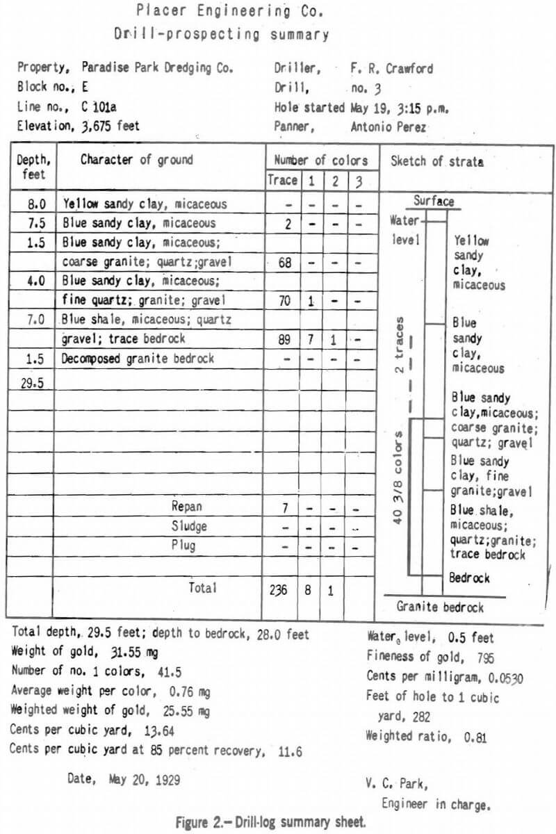
Systematic records of the results of drilling are essential to the subsequent calculation of values and. yardages. Figure 2 shows a drill log, or summary, which provided for a complete record of the information gained from a single hole. It was printed on 8½- by 11-inch loose-leaf sheets.
In the work on which this record form was used the panners were trained to classify the gold particles of approximately 1 mg in weight as no. 1 colors. Eight fine traces, or four coarse traces, were supposed to equal one no. 1 color. Four no. 1 colors equalled one no. 2 color, and four no. 2 colors were equal to one no. 3 color, or 16 mg. Colors heavier than no. 3 were weighed separately and calculated accordingly. In practice, the weight of the panner’s no. 1 colors, as checked by the final weighing of the gold from each hole, was generally found to be between 0.75 and 1.5 mg. This classification of colors was made as a convenience in estimating the distribution of the gold through the strata. Data recorded by the driller in his drill logs comprised the times of starting and finishing, the number of different sizes of colors found at each pumping, notes on the nature of the gravels, depth measurements, and measurements of core rise and sludge volume. The last was taken by dumping the sludge into a cylindrical container of the same inside diameter as the casing and noting its height. Notations were also made of the colors obtained by repanning the tailings and by panning the settled sludge and the plug of gravel taken from the casing upon pulling it, after the hole was finished. The engineer in charge transcribed these items onto the sheet and proceeded to make his calculations. The measurement of core rise, usually about 15 per-cent within the casing and of sludge volume both were used to calculate the “weighted ratio” (0.81), which indicated that, an excess of material was taken from the hole; hence, the weighed quantity of gold recovered was reduced in the calculation from 31.55 to 25.55 mg. As 282 feet of hole with 4-inch casing was taken as equivalent to 1 cubic yard, the gold content of the gravel in cents per cubic yard was calculated by dividing 282 by 28.0, the depth to bedrock multiplying by 25.55 and again by 0.0530, the value in cents per milligram of gold 795 fine (with gold at. $20.67 per ounce).
A sketch of the strata penetrated was made by the engineer from the drill crew’s notes and his own observation. On it were recorded the numbers of colors recovered from the gold-bearing strata, thus showing at a glance the geology and value of the gravel at that point.
Table 4 contains data on a number of placer-prospecting campaigns and was supplied by G. A. Bigelow, placer-mining engineer of San Francisco. He states:
The prospecting was carried to a conclusion in each instance, Dredging followed the prospecting in four of the six cases.
The large difference in cost of engineering between jobs no. 1 and no. 2 was due to the much larger overhead at no. 2 on account of the nature of the deposit. The distance from headquarters at San Francisco also affected the size of the engineering force necessary on the ground. Job no. 3 was in effect two jobs. The work was interrupted for a full year.
Job no. 4 was favored by an ample force of experienced gravel miners, a low water level, and not a difficult quantity to handle. Diaphragm bilge pumps were used and in some shafts too deep for suction, a second shaft sunk 10 feet deep and adjacent to the first was used for increasing the effective depth, by means of two lifts.
Job no. 5 was a very difficult undertaking and required the use of steel telescoping caissons, especially designed for the job. Gasoline-driven pumps of the jackhead deep-well cylinder type proved very awkward but most effective.
In both jobs no. 4 and no. 5 the total contents of the shafts were washed in a long-tom device by hand and in job no. 4 a check sample was cut from the side of the shaft and washed in a rocker.
Job no. 6 is a typical case of shaft prospecting in frozen ground where the gravel deposit is unusually thin or shallow. Here the conditions for shaft work were very favorable, but the high cost of living was reflected in the unit cost. Where experienced men are available, as in this case, and equipment developed by the miners for inaccessible places is at hand for their use, a very low unit cost is obtained.
Drilling in frozen ground is also very economical, owing to the speed with which the work is accomplished and the absence of casing costs. The volume of sample is quickly and accurately obtained by water measurement after completion of the hole.
The unit cost or cost per foot for placer prospecting is usually uncertain, since it depends upon the total footage. The number of holes or cross sections as the case requires may prove to be very few, and the total cost of starting and clearing up the job falls upon a small total footage. Two cases can be cited as follows: One in Colombia, S.A., cost about $25,000 for about 1,500 feet of drilling where the equipment was left behind and never salvaged. Another in central Alaska cost about the same for less than 500 feet of drilling where the equipment was not salvaged on account of cost. In such cases and in many others that constantly arise costs can be reduced to a very low figure by a preliminary examination made by an experienced and reliable placer-mining engineer and are usually represented by the engineer’s fee and expenses. The number and distribution of prospect holes needed to provide the essential information can be readily determined by the preliminary survey.
Rich, deep-lying channels, such as those in California, which are worked by drift-mining, usually are prospected and developed by drifting, because the pay streaks are too small in area and too erratic in value to be amenable to drill-sampling. However, drilling may be of great value in determining the nature of the gravel, depth to bedrock, and location and grade of the deep channel. At the Vallecito Western drift mine near Angels Camp, Calif., drilling was applied in this way. Steffa states:
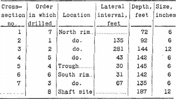
The broad Tertiary valley east of Six Mile Creek was prospected by churn drilling to discover the location of the actual channel. A north-south line of holes was drilled across the valley, spaced as shown in table 1 and figure 1 A. The holes were not drilled in regular order across the valley. The first was drilled north of the valley center in order to determine the bedrock gradient of the north rim and struck bedrock at a depth of 92 feet. This depth and the distance of the hole from the outcrop of the north rim of the channel permitted an approximate calculation of the slope of the north rim. Known elevations of the channel floor at points exposed by mining operations 2 miles west of this section indicated a depth of overburden here of about 150 feet. The second hole, drilled 281 feet to the southward, reached bedrock at a depth of 144 feet. The third hole was intended to be on the south rim and, in fact, struck bedrock at a depth of 135 feet. The fourth hole, with the information then available, was aimed for the channel trough, and the fifth and sixth were drilled to explore the width and possible pay area of channel gravels. The seventh hole was drilled north of the first hole to test for a possible split in the ancient river trough, but none was found, the hole bottoming on bedrock at 72 feet.
The drilling order, location, depth, and size of churn-drill holes are shown in the following tabulation.
The. drill sludge from the first 100 feet of holes in the vicinity of the channel proper was sampled intermittently. From that depth to bedrock each 5 feet was sampled carefully. The sludgs was weighed first and then passed through a rocker. The concentrate was panned and the gold weighed.
The drill rig used was an assembled outfit purchased by the company and was powered by a 10-hp. gasoline engine. The crew consisted of a runner and a helper. Six and twelve inch “Mother Hubbard” type bits were used.
All of the seven prospect holes were drilled without casing, except one where it was intended to sink a prospect shaft; the plan was later abandoned, however. Two more holes were lost, one at 82 feet, due to casing trouble, and one at 57 feet when a large quartz boulder was encountered which neither hammering nor blasting would dislodge. A tenth hole was sunk at the present shaft site, as described later. All drilling was done on company account. The total footage was 1,198 feet, drilled in 278 working days, or an average of 4.3 feet per day. The average cost was $6.11 per foot. The costs of drilling the 6-inch and 12- inch holes were practically the same.
As it happened, the estimates based on the results of this drilling and sampling were proved by later underground development to be fairly accurate. Drilling, however, should not be depended on for the exploration of such deposit’s, as the gold concentration is usually erratic. The recovery of gold from the drill sludge should be taken merely as an indication, of the presence of ore in the stream gravels, the quantity and distribution of which must be determined more closely by drifting and finally by extraction.
The Continental Dredging Co., at Breckenridge, Colo., in 1930 and 1931 drilled about 1,500 feet of 6-inch holes, averaging 50 to 60 feet deep, in bouldery ground. The cost of this work was $2.87 per foot.
The cost of maintaining a single drill crew for sampling dredge ground at Oroville in 1932 was about $1,000 per month; the cost per foot of hole drilled was $2.50. The gravel was about 50 feet deep.
The property of the York Mining Co. near Helena, Mont., was prospected by drilling. The following data were furnished by N. C. Sheridan, the engineer in charge. The deposit was a stream placer, consisting of about 3 feet of gold-bearing gravel covered by a thick layer of black mud and soil, locally known as “beaver muck”, to an average depth of more than 50 feet above bedrock. Holes were drilled 20 feet apart in transverse lines as much as 800 feet long across the bottom of the valley. Five such lines were drilled within 1¼ miles along the stream, with a total of 154 holes averaging 54 feet deep. A Star drill rig was used, powered by a 10-hp. gasoline engine which consumed about 1 gallon of gasoline per hour. The holes were cased with 5-inch pipe in 4- to 8-foot lengths, The drill crew consisted of a driller at $4.00 per shift, a panner at $4.50, and a helper at $3.00. An average of one hole per 8-hour shift was drilled at a cost of $0.50 per foot. The overburden was barren and so soft that the casing could be driven to the gravel stratum in about 2 hours. The holes were sunk 2 or 3 feet into the soft bedrock to insure complete recovery of all gold.
A dredging property of the Trinity River, Calif., was drilled about 1922 and again in 1928. The gravel was 10 to 45 feet deep, overlying slate or greenstone bedrock; the pay streak ranged from 100 to 800 feet wide. Large boulders were hot numerous, and the gravel was relatively free from clay but was cemented in places. Along the river the gravel was saturated with water, and shaft-sinking therefore had been found impractical. The gold was fairly coarse and was not confined, to bedrock but occurred. anywhere from 1 to 15 feet above it. Requa states:
The property was sampled in three stages: (1) The southern end of the property was drilled by the Metals Exploration Co. prior to the time that the dredge was built in 1923. About 100 churn-drill holes were put down at that time. A few shafts were sunk but the greater part of the prospecting was done with a steam-driven Keystone portable rig, using standard prospecting casing with an inside diameter of 6 inches. The holes were spaced 125 feet apart in roughly parallel rows 750 feet apart. (2) The upper ground was prospected by the Shasta Dredging Co. in 1922, using the same rig that was used in prospecting the ground of the Metals Exploration Co. Over 60 holes were put down in rows about 900 feet apart with the holes spaced 150 feet from each other. (3) When the present owners were investigating the possibilities of dredging from the lower to the upper ground, 27 churn-drill holes were sunk in the 8,000-foot interval between the two previously prospected areas. The rows of holes were about 750 feet apart, and the holes were spaced 125 feet from each other in the rows. The same drill rig was used in this prospecting that had been formerly used.
The cost of prospecting can be stated only for this last stage of the work, which was done in 1928. The wage scale was as follows:
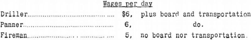
The cost was $7.23 per foot. This included the salary of the engineer in charge and the entire cost of a new string of drill pipe which, however, was not worn out in the prospecting.
The relative merits and applications of shaft-sinking and churn-drilling are the subject of some difference of opinion. Usually, where either method can be applied, shaft-sinking is slower and more costly but more accurate; furthermore, it yields more definite information as to the physical characteristics of the gravel. Any one of these factors may assume such importance as to remove all doubt which method to use. For instance, if the values in a tract of dredging ground are close to the margin of profit by dredging, accuracy of sampling becomes of primary importance, and the cost and speed of sampling have less moment. Conversely, if the sampling is being done for purposes of dredge control on land already held, the cost probably will be the determining factor.
Some ground cannot be sampled accurately by drilling, either because it is loose and coarse, which makes it difficult to recover the gold, or because it is so wet and soft that it is impossible to be reasonably sure of the true volume of sample obtained. Under such conditions shafts should be sunk even if caisson methods are necessary. For a small job churn-drilling would be too costly because of such expenses as first cost of drilling tools and casing, moving into district, and similar overhead or general charges, unless the location is such that equipment can be rented cheaply or unless some contract driller will make a reasonably low bid. Shaft-sinking normally requires very little equipment. Any mining district will furnish miners to sink the shafts, and shaft-sampling is relatively simple and subject to repeated checking as long as the shafts remain open. On the contrary, churn-drilling and churn-drill sampling require the services of an organization whose experience with this particular work and whose reliability and integrity will permit confidence to be placed on the returns.
If it is assumed that the drilling and sampling have been done in the most careful and suitable fashion the significance of the recorded quantities of gold washed from each sample depends wholly on the ensuing computations. First, an assumption must be made as to the volume of gravel represented by each foot of hole drilled; second, it is customary to apply, sometimes, in the same volume factor, sometimes as a separate calculation in the head office, a correction for losses in dredging. Only wide experience can teach the engineer what these factors should be, as he cannot see what happens at the cutting shoe of the drill, and no satisfactory determination of dredge recovery has ever been made. The drill removes, theoretically, a cylinder of gravel equal in diameter to the outside diameter of the cutting shoe and 1 foot long for each foot drilled. Actually, some gravel may be pushed ahead or aside, or some may run into the hole from outside the casing. In either case, if the deficiency or excess can be detected by observation of the sludge a correction must be applied; this is generally an empirical factor that is accurate only in proportion to the engineer’s experience in such work.
Because the outside diameter of the standard cutting shoe for 6-inch casing is 7½ inches the maker of Keystone drills recommends, use of 0.3068 square foot to represent the average cross-sectional area of the hole drilled, this being the exact area of a 7½-inch circle. The complete formula reads:
Value of gravel in cents per cubic yard equals weight of gold recovered in milligrams times value of gold in cents per milligram times the conversion factor 27 (cubic feet per cubic yard), divided by the depth drilled in feet times the cross-sectional area of the hole, or briefly,
V (cents per yard) = weight, of gold (mg) x 0.06 x 27/depth drilled (feet) x 0.3068
The factor 0.3068 is sometimes changed for various reasons. Other common factors are 0.2700 and 0.333, which represent the sectional area in square feet of 7- and 7 13/16-inch holes, respectively. Use of the smaller figure, known as “the Radford factor”, raises the estimated value of the gravel about a tenth, whereas the larger figure has the opposite effect.
In the drilling of the area on Trinity River estimates for part of the field were based on the use of the factor 0.27. As it was believed later that these results were erroneously high the adjacent ground drilled subsequently was estimated by the use of the regular Keystone factor 0.3068.
There is a great difference of opinion among engineers regarding interpretation of the results of drill sampling. Some would take virtually no account of sludge measurements. Others insist that the sludge should be measured in calibrated boxes and a correction applied accordingly. Still others make a practice of settling and measuring the mud from the run-off and at the end of drilling make use of the volume of this slime to correct their sludge volumes. Another procedure is suggested by W. W. Avery, who states that the height of core in the pipe should be measured both before and after driving the pipe and a correction made based on the actual as compared with the theoretical rise. The assumption is that the rise of the core when driving the pipe should exactly correspond to the volume of material displaced by the walls of the pipe; if not, an excess or deficiency in the sample is indicated which should be compensated in estimating the values per cubic yard.
The interpretation of placer drilling and the effect of spacing of holes also have been discussed widely. In a recent contribution to the subject the author argued briefly that some maximum spacing, or maximum undivided liability per hole, should be fixed for all drilling which was to be the basis of an examining engineer’s report. The ensuing discussion by a large number of engineers brought out a distinct preference for relying on the engineer’s education and experience but also the need for a clear statement of the method of making the estimate. It was said that the application of drill and recovery factors could affect the value of a deposit as much as 25 to 50 percent. One New York mining company was said to have had such difficulty in interpreting its engineers’ reports because of the different factors used by each that they finally were instructed to report merely the basic figures, such as are contained on drill logs, after which the calculations were made in the home office.
One theory of drill sampling is that the drill holes should be spaced wide apart at first, then checked by subdividing the original network of lines or squares. If the result of all the drilling is different from that of the first set of holes, still further work at closer intervals is desirable until the addition of holes fails to alter the estimate of value by an important amount. Such a procedure must, of course, be planned carefully in advance, and the engineer must use his judgment as to the importance of the possible error and balance this against the known cost and delay of additional drilling.
R. G. Smith believes that average drill results are low because test shafts sunk on drill holes usually give higher returns. He cites 4 sets of 3 to 5 shafts each, which individually indicated values ranging from 96 to 191 percent of the drill-hole returns. By groups, however, the average shaft value was close to 140 percent of the drilling results. This was in ground so firm that the shafts stood 30 to 60 feet deep without timbering. The drill factor 0.30 was used. At a dredge property in Idaho it was stated recently by the operators that shaft sampling had given results two or three times higher than drilling. The discrepancy was believed to be due to the presence of about a foot of loose sand just above bedrock and to the bedrock being so soft as to hinder drill recovery.
A good discussion of the accuracy of drill sampling of dredge ground is given by C. W, Gardner, a veteran dredge operator. The data contained therein are shown in table 5. Excluding all areas of less than 20 acres and not considering the last four listed, which were sampled by sinking shafts, the average departure from 100-percent recovery is 27 percent plus or minus; the average gain is very nearly equal to the average loss. Gardner states:
From all the properties above mentioned it is possible to segregate 3,743 acres, to which data given in fairly accurate reports can be applied. This combined area was prospected by means of 1,749 drill holes, or one to every 2.1 acres. The average value per cubic yard obtained by drilling was 15.4 cents and the average dredge recovery 13.55 cents, or 88 percent.
It is apparent that the sampling of dredge ground is far from a precise science. Certainly such large discrepancies would, not be expected in sampling low-grade ores, and obviously no refined calculations can be based on such work. On the other hand, it must be remembered that no final proof of the accuracy of placer sampling is ever possible and that dredging involves a metallurgical operation which is subject to many disturbing effects. These facts are discussed further in the chapter on dredging in a subsequent paper.