Table of Contents
In the preliminary phases of mine planning it is often desirable to quickly estimate approximate sediment basin construction costs based on readily available physiographic data for a large number of proposed sedimentation ponds. A procedure is presented whereby sediment basin embankment volumes, disturbed areas, and principal spillway pipe lengths can be quickly estimated with acceptable accuracy.
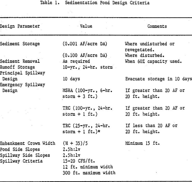
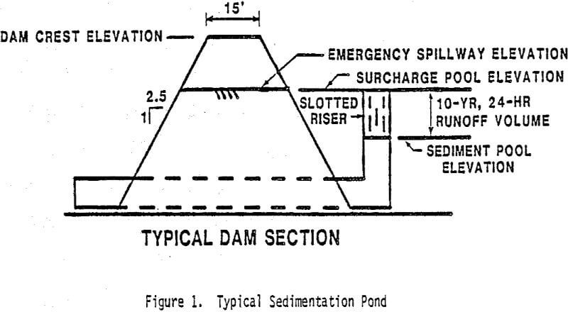
Sedimentation Pond Design Criteria
Runoff hydrographs yielding peak flows and runoff volumes were required for these analyses. These values are dependent upon many things including:
- Drainage Area
- Rainfall Volume
- Rainfall Temporal Distribution
- Rainfall Losses
- Basin Storm Response
- Vegetative Cover
- Topography
- Soils
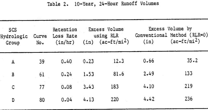
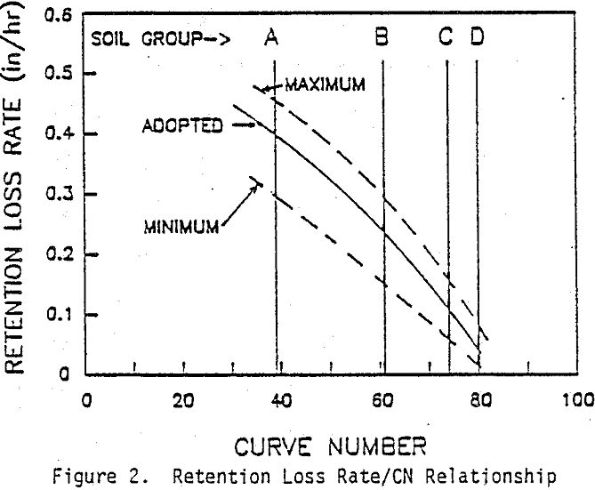
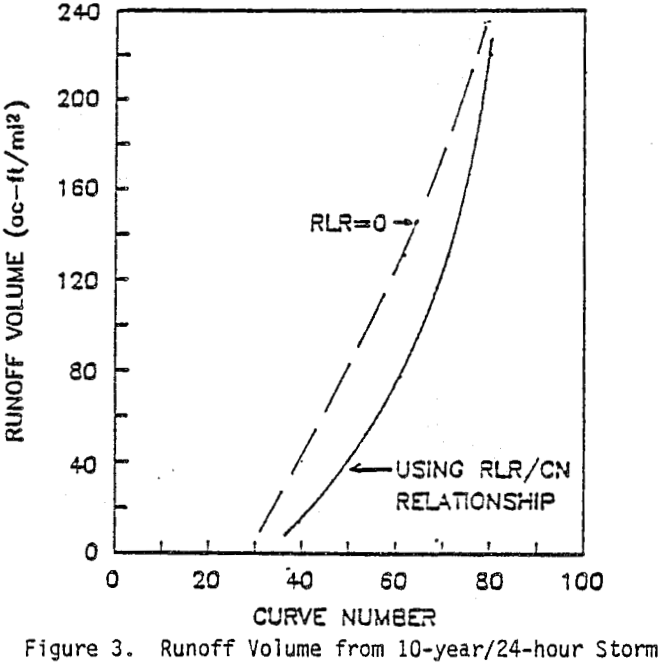
Modeling was based on unit hydrograph theory. Rainfall volumes were found for the site for 24- and 6-hour duration storms and return periods of 10-, 25- and 100-years. The Soil Conservation Service (SCS) Type IX, 24-hour rainfall distribution was used. The standard SCS loss function and unit hydrograph were employed due to their relative ease of use and general acceptance.
Sedimentation Pond Design Procedures
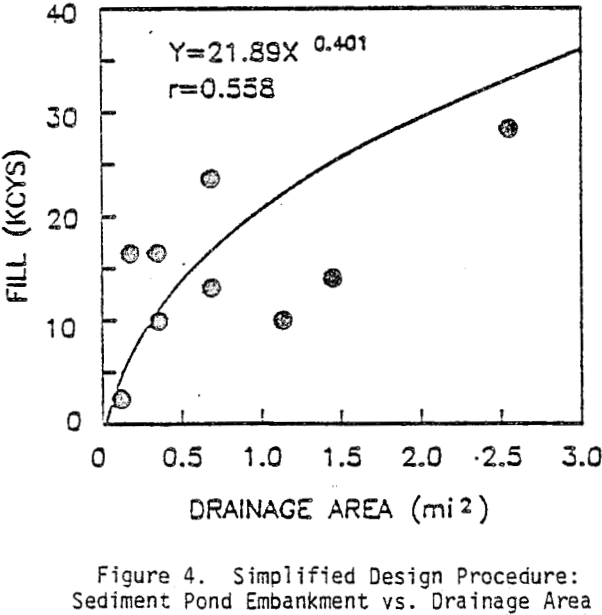
Two approximate procedures were developed to find the embankment volumes associated with sedimentation ponds. By performing a detailed analysis of a few representative basins, a generalized relationship was developed to facilitate the conceptual design of the 95 basins in the plan. This was done to eliminate extensive hydrograph and reservoir routing simulations.
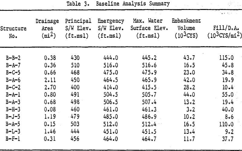
Twelve sedimentation pond sites were chosen that were representative of the drainage area distribution of all of the required ponds for the project. Detailed analyses were done using the HEC1DB model developed by the U.S. Army Corps of Engineers Hydrologic Engineering Center, Davis, California using the design criteria described.
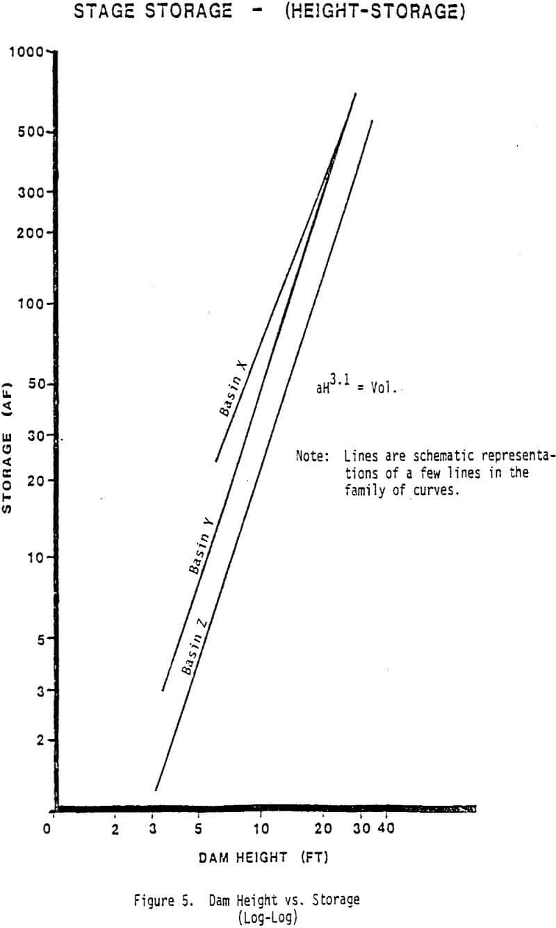
The detailed analyses of these 12 sediment ponds occurred as follows. Stage-storage curves for each dam site were developed by planimetering each five foot contour on the topographic map. The principal spillway elevation was determined from the required sediment volume, conservatively taken to be 0.1 acre-feet/acre of disturbed drainage area. This volume of sediment storage was plotted on the stage-storage curve to determine the required elevations.
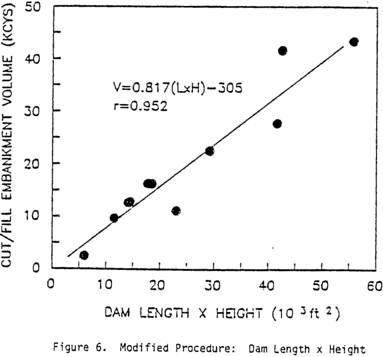
Three important aspects of the detailed analysis were: 1) planimetering for the calculation of the stage-storage curves; 2) routing using Modified Puis method; and 3) data preparation and use of cut-fill program. Logical design simplifications to the detailed procedure were made in each of these aspects.
Error Analysis
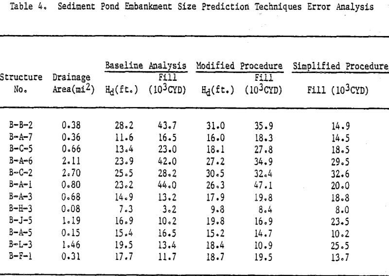
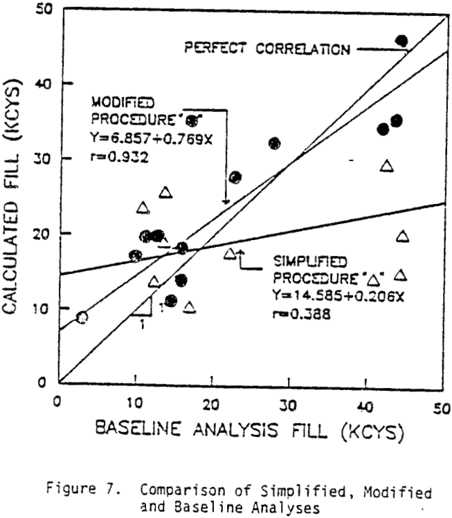
An error analysis was performed comparing the embankment volumes as calculated by the detailed procedure with the proposed drainage area-to-fill volume regression and the modified procedure previously discussed. Although it is not correct to test the validity of a model with the data on which it was calibrated, this exercise shows the effect of cumulative errors over the several steps of the modified procedure.
The baseline calculations on the runoff volumes and peak discharges can be developed using other techniques as deemed appropriate by the designer or can be developed using values previously generated for the area for previous designs.