Shell liners wear very fast in very large diameter autogenous and semi-autogenous mills. In addition to shell liner wear, the ends of the mill are susceptible to very high rates of wear, generally confined to fairly narrow bands. Due to the sheer size of modern mills, extensive downtime is required to replace shell liners or end liners. The inserted liner has very definite application here, as abusive impacting service causes extreme wear.
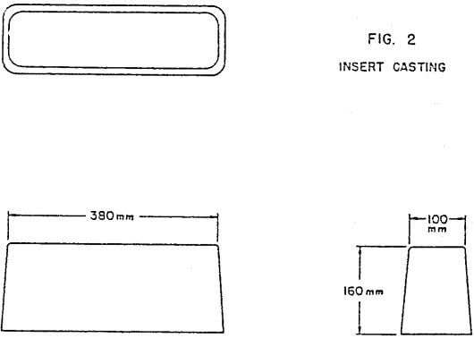
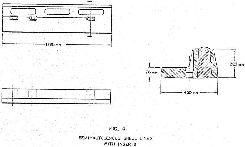
Rail liner profiles are generally preferred for shell liner configurations. This rail liner (Figure 3) is typified by a ratio of valley to lift width of 1:1, one lift per chord length, and lift height to valley thickness ratio of greater than 2.5:1. By inserting harder, more wear resistant material in the lift area improved life can be achieved (Figure 4). Metallurgically, advantages can be obtained by utilizing this scheme.
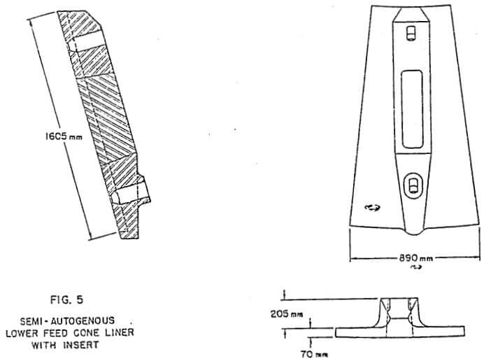
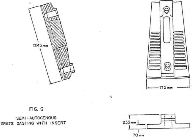
Incorporate the insert concept with advanced design techniques to provide significant life improvements of head liners (Figure 5). An important consideration here is that by eliminating bolt holes, in combination with proper selection of head liner design, it is possible to isolate the narrow wear band on a single piece, and, the inserting of an abrasion resistant material, will result in a liner whose scrap weight is very low with significantly extended liner life. The narrow wear band is not confined to the feed head of the mill. Grates typically are located within the intensive wear zone at the discharge end of the mill. Single piece grates with cast-on lift areas appear to be the preferred configuration as opposed to grate and lifter bar pieces. Development of a single piece grate segment tends toward a large cast-on lift area to combat severe wear. This cast-on lift area offers the perfect habitat for inserting with improved wear material (Figure 6).
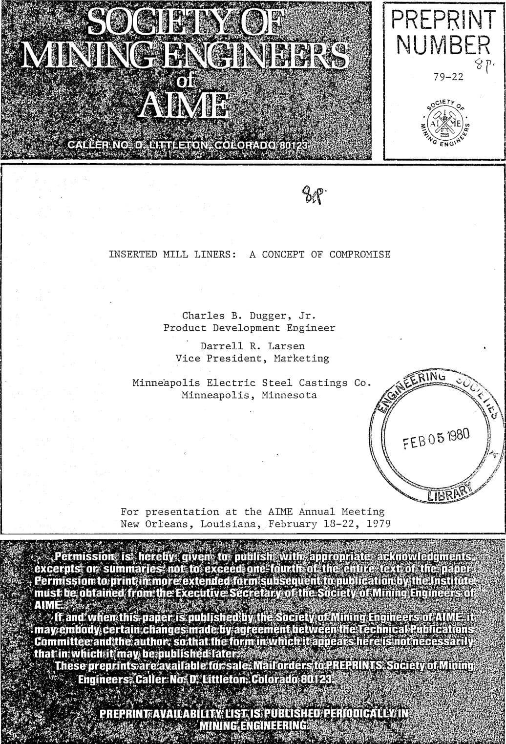
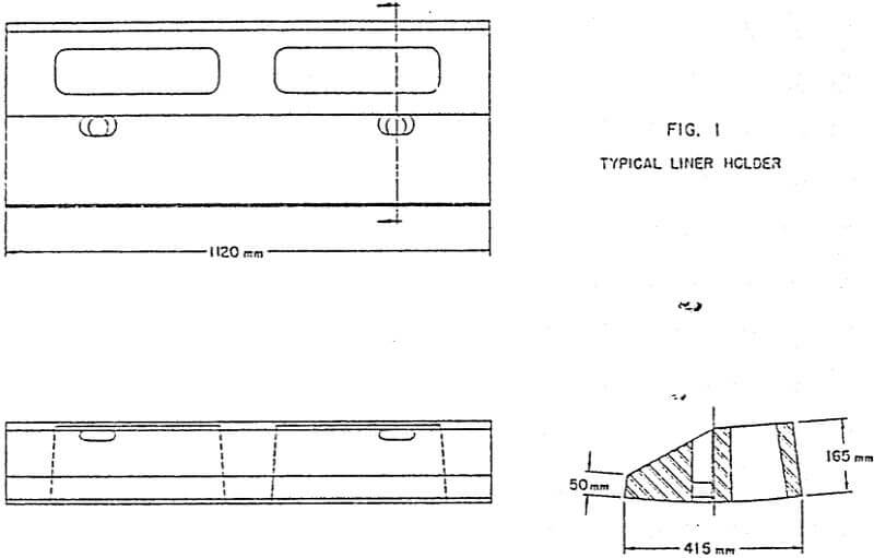
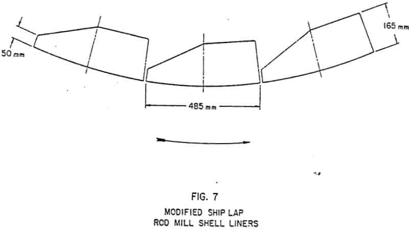
Modified ship lap profile rod mill liners (Figure 7) have demonstrated superior performance to single wave liners. The profile of a modified ship lap liner offers one of the most ideal locations for an insert of hard, abrasion resistant alloy. Typically, discharge shell liners in a rod mill receive such severe punishment that they limit design and alloy selection. Modified ship lap profile liners, (Figure 1) utilizing an insert of hard white iron installed in the discharge position of a rod mill, offer extended life for a set of shell liners. Many times the center and feed end liners of a rod mill receive such impacting that the most favorable abrasion resistant alloy cannot be used. Again, a set of inserted rod mill liners can provide the best possible liner life available.
Utilization of hard white iron liners in primary ball milling is currently in practice at a number of locations. It is important to operate large diameter primary ball mills in such a manner as to provide conditions capable of allowing utilization of very hard white irons. Wear life of liner parts can be extended by providing system safeguards. Accordingly, it appears that the insert does nor have as broad an application since wear life is capable of being maximized with conventional alloys.
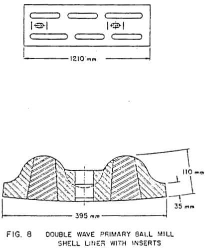
However, certain conditions do exist, and it is possible to geometrically accommodate the generally acceptable double wave profile with inserts (Figure 8). Accommodation of the insert-system to double wave liner configurations, within constraints of readily and economically available alloys, is not limited to improved liner life. Improved metallurgy can result by providing differential wear characteristics of wave and valley.
 |
 |
 |
 |
 |
 |
 |
 |