Table of Contents
The trend of the past five years toward larger mill sizes shows no signs of reversal. Indeed, the current view of capital requirements for projects, coupled with decreasing ore grades, indicates at least a constant if not accelerating demand for the use of the larger mill, rather than several smaller ones for a given size project. The continuation of this trend, in spite of occasional mill failures, in both the SAG and ball mill areas, requires a requestioning of some basic design philosophies up to now utilized for large mills.
The structural design criteria, simply stated, is based on two pieces of knowledge:
- The stresses existing in any area of the mill.
- The failure stresses and modes for this area of the mill.
Testing For Stress Model Evaluation
There are two kinds of tests that may be practically performed in the grinding mill area; those aimed at obtaining stress data and improving analytic predictions, and those aimed at gathering failure data. The first kind is discussed below.
Scale model tests have been highly advertised in the mill fabrication industry. This is actually quite misleading, for scale model tests can lead to only very limited results for our purposes. In listing any mill failures, there is almost none that has occurred in a clean plate area away from small discontinuities or junctions. Yet these are the only areas in which scale models are generally valid.
The scale model is useful in providing an overall check to analytical predictions of stress. But again, this usually excludes areas of high local variation. Thus, it may check out, and provide guidance for, an overall analytical model, but rarely for a detail analytical model of an area of expected high stress variation and potential failure. For these reasons, full scale prototype tests on actual running equipment are required.
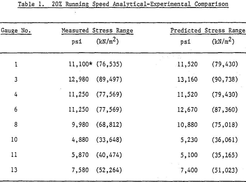
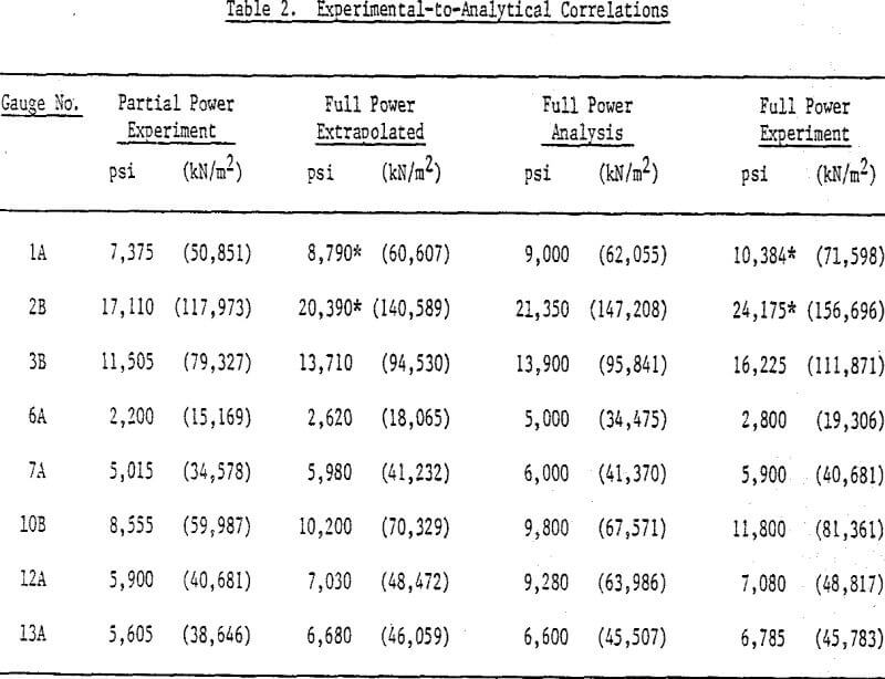
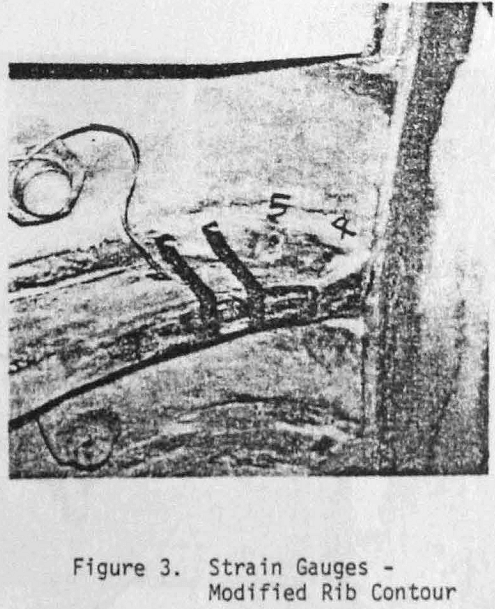
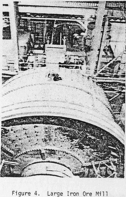
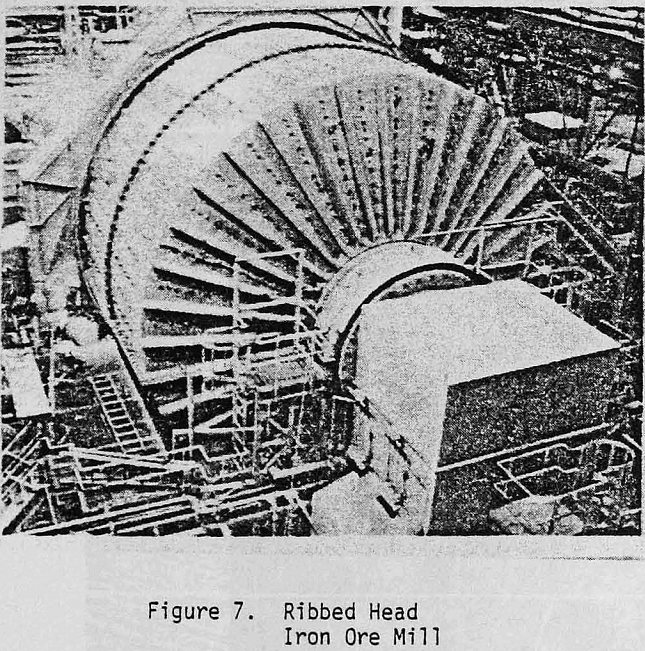
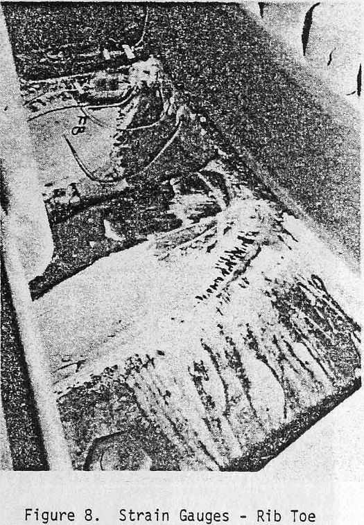
After a large iron ore mill experienced failure at a welded joint, consultants were asked to investigate the failure. After the strain gauge program, the consultants report showed analytical-experimental correlation at the peak stress location, but hardly anywhere else. Nevertheless, further analytical results were used to investigate alternatives.
It was finally determined that the experimental program was carried out after serious weld repairs were performed. Thus, it was concluded that weld residual stresses, although not being measured, were still being felt, since it became likely that the strain gauges were in an area which may go somewhat into the nonlinear range during stress cycling, due to the high residuals present.
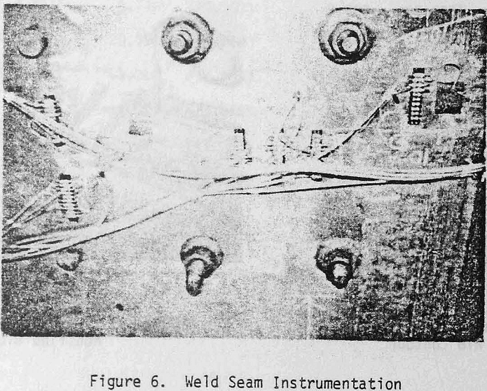
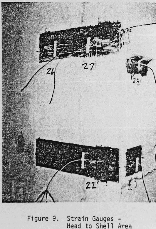
Gauge 6A is near a mechanical joint which was analytically assumed as solid. A displacement probe near this joint showed some action, thus verifying that the solid assumption would significantly overpredict stress. Gauge 12A was near a variety of gussets near the gear end of the mill, and not knowing its exact location, the analytic prediction here is only an order of magnitude comparison.
Testing For Casting Stresses
In the previous section, full scale tests were discussed as a means to verify analytical modeling procedures in local high stress areas. These investigations were carried out mainly on steel plate material at, or near, welds. Thus, the difficulties in analytical modeling were concerned mainly with rapid geometric changes.
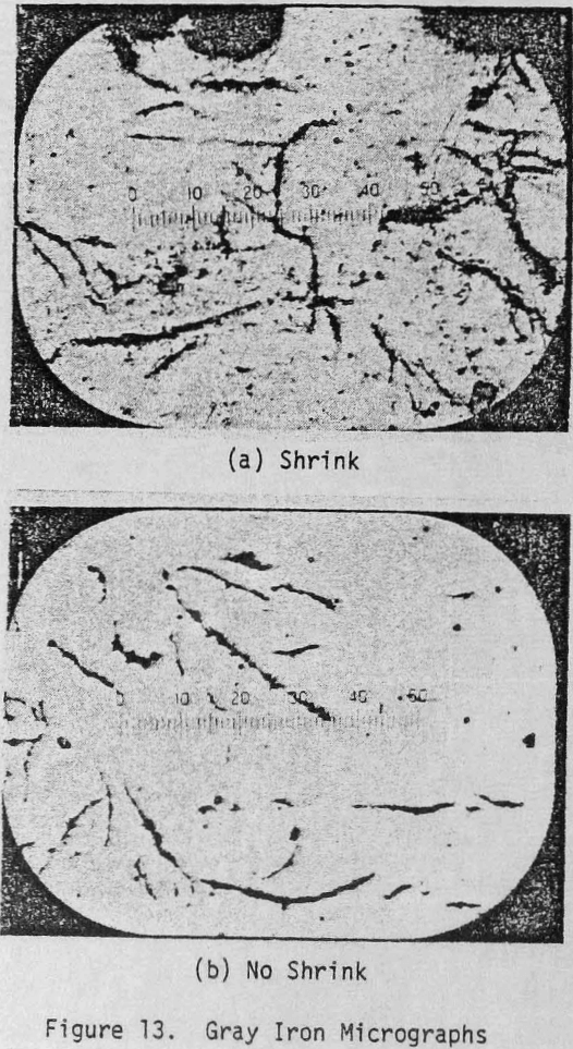
In the purchase of steel plate, because of its forming process, one usually requires only a knowledge of its chemical and mechanical characteristics in order to satisfy a specification. Nevertheless, weld areas are still usually scanned for laminations. In cast iron, a series of test’s must be made in order to evaluate the casting soundness. Testing must be done to evaluate the cast iron chemical and mechanical properties, and testing must be done to evaluate its internal geometric soundness.
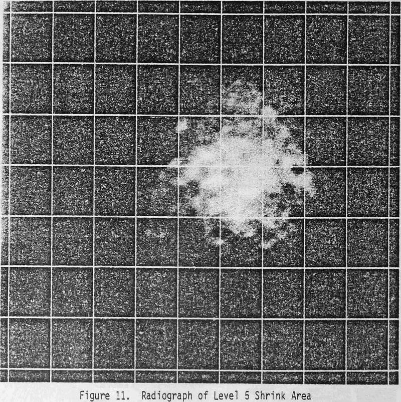
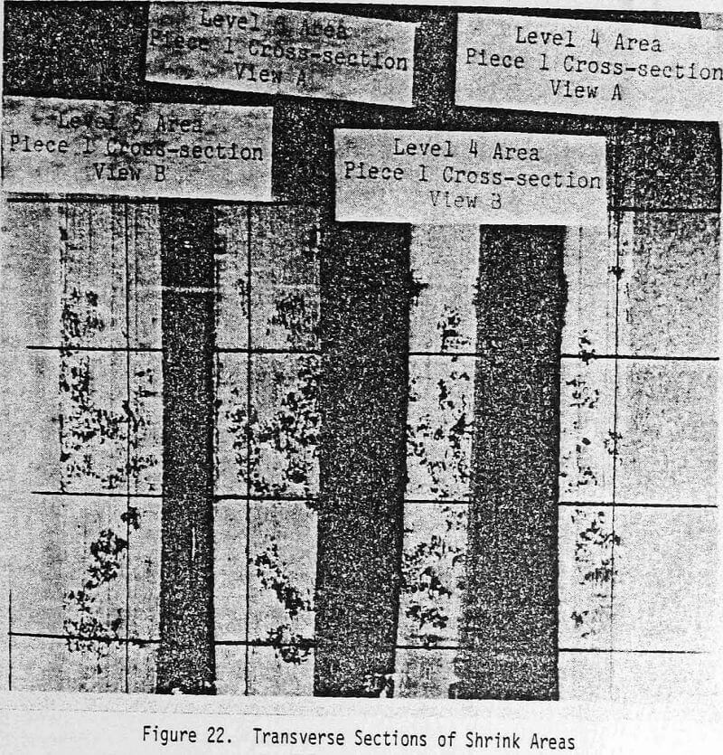
The casting quality, however, after all these tests, is still indeterminate since there may be areas of shrink, porosity, inclusions or other subsurface aberrations which have not been found. Thus, testing by radiography is mandatory to determine the actual casting quality, since this finally gives a look at the casting interior geometry.
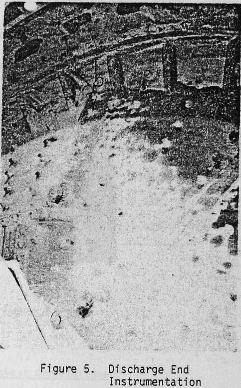
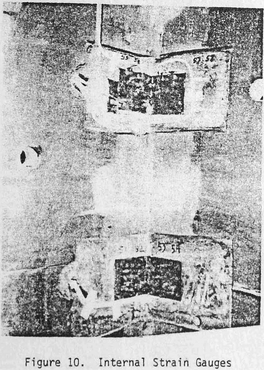
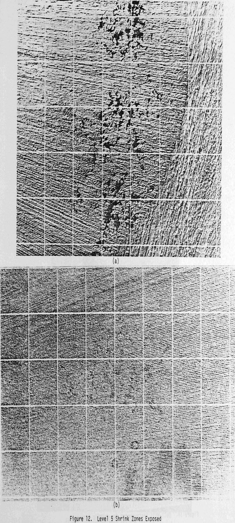
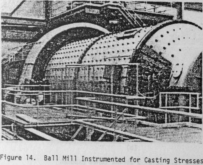
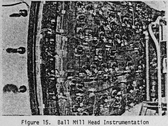
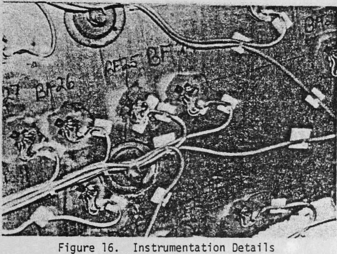
Eighty points on the ball mill (36 feed head – 44 discharge head) were instrumented on a grid pattern with strain rosettes for triaxial strain measurement. The grid pattern included clean casting areas, areas of low level shrink, and areas of very high level shrink. The following ratios were found:
a) Maximum ratio of stress range in the high shrink area to stress range in a corresponding clean area = 3.2. This included areas which were in close proximity to liner bolt holes.
b) Minimum ratio of stress range in the high shrink area to stress range in a corresponding clean area =2.0.
c) Maximum ratio of stress range in test to stress range predicted by analysis = 1.65.
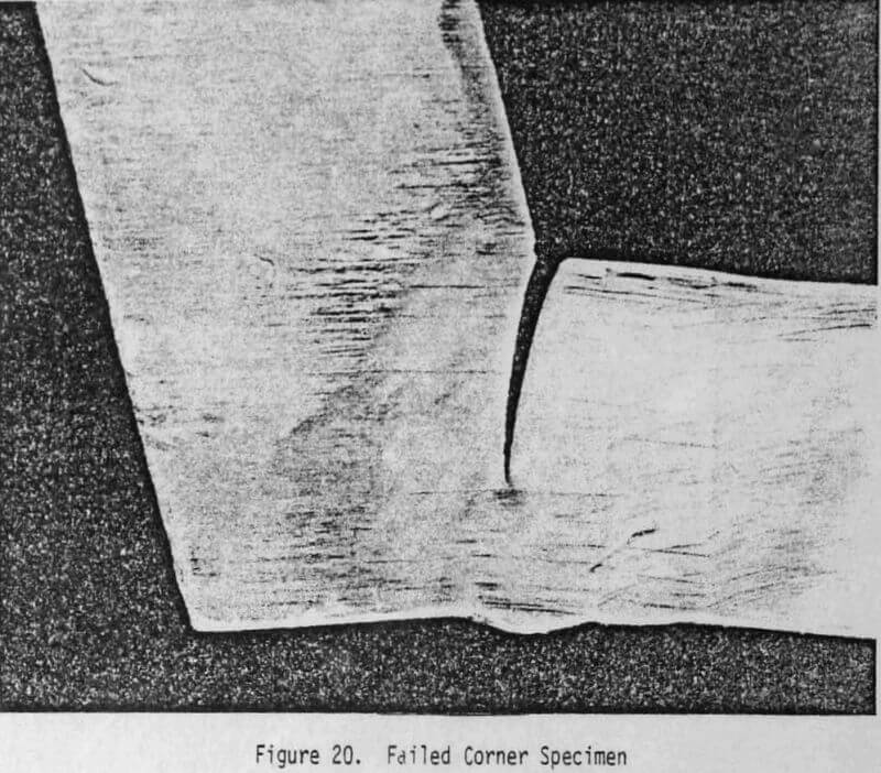
Testing For Failure Criteria
These types of tests, however, are not tailored for failure criteria definition, in the fact that they are not destructive. Fatigue failure phenomena are defined by long term destructive tests, not by the short term tests discussed previously.
The information required from the fatigue tests would be as listed below.
- For welded joints in mills
- For castings in mills
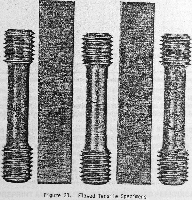
Component testing for fatigue failure data is valid if the test component is representative of the actual component in terms of expected flaw distributions, thermal history, stress pattern, etc. The simplest way of achieving these requirements is to use full size components.
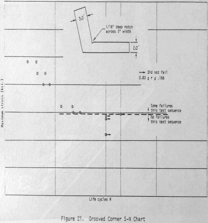
The tests are set up in such a way that the representative stress pattern amplitudes are varied so that specimen failures may be expected at varying cycle lives.
Castings: Fatigue testing in castings is actually more difficult than in weldments, in the mill fabrication industry, due to the size of the castings used. Since the sizes are so large, the full scale tests described above become impractical, and the problem is one of scaling the effects of discontinuities such as shrinkage.