Table of Contents
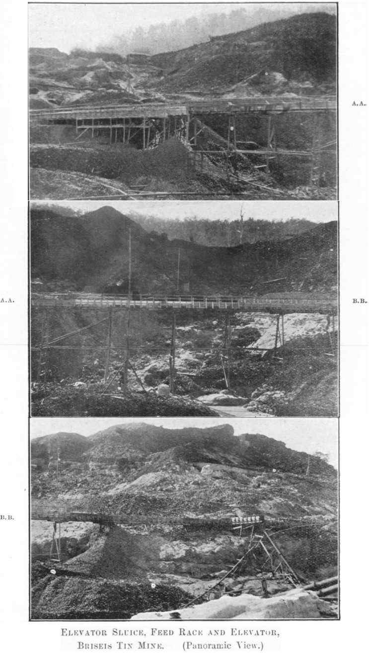
In this paper an attempt is made to describe the sluicing operations on the tin fields of north-eastern Tasmania. No claim is made to completeness, for much of the ground has already been covered, and nothing is to be gained by needless repetition. On this account some portions of the subject have obviously received but scanty attention in order that others may be rather more fully dealt with; for instance, figures referring to the accuracy of various methods of valuing alluvial deposits, particulars of efficiencies, and water duties on both overburden and drift; also, the system of recording water distribution. The plans of the tin-streaming shed, sluice and feed-race, and overburden tailrace represent types of the most modern design.
Tin Geology
The principal alluvial deposits being worked at the present time are situated either in the ancient or modern bed of the Ringarooma River or its tributaries. This river flowed in a northeasterly direction, receiving numerous tributaries on either bank, and finally emptying into Boobyalla Harbour, The most important of these tributaries, from a mining point of view, are the Cascade, Main Creek, Weld and Frome Rivers (which unite just before joining the modern Ringarooma), Wyniford River, and Bradshaw’s Creek.
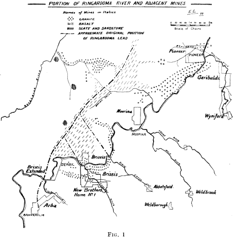
All except the last-named flow north-westerly, showing that the general fall of the country on the right bank was in that direction. It is significant that at the junction of the tributaries with the main river are situated most of the leading mines of the field.
The whole of the district originally drained by this system consisted of granite and some sedimentary rocks (slates and sandstone) into which the granite was intruded. Most of the sedimentary series have been removed by denudation, and at the present time the granite is the predominant rock of the field. It forms the bedrock of all the tributaries, and also of the main river itself as far as determined. But, what is of more importance from a mining standpoint, the granite, or much of it, is tin-bearing, and the denudation and disintegration of this stanniferous rock is the source from which the tin-bearing alluvial deposits have been derived. The conditions are very favourable for rapid denudation, as the agencies that play the chief part in this process are all present—viz., heavy rainfall, extreme cold and moderate heat, strong winds, frost and ice. The rain and winds cause the products of denudation to be removed quickly (the steepness of the hill-sides being also a favourable condition), and the disintegrated material rapidly finds its way into the creeks and rivers, leaving the original granite exposed to the same weathering agencies as before. That an enormous amount of denudation has gone oil is evident from the extent of the deposits in the tributaries and the main lead, the latter alone having been traced for upwards of thirteen miles in length, over a mile wide at the northern end, and about 230 feet in depth.
Although this paper is intended to deal with the alluvial deposits only, it should be stated that a large number of mines have been worked and a few are still operating on lode formations. In these deposits the tin is present either in small lodes, stockworks, or in large low-grade bodies of metamorphosed stanniferous granite, bounded by barren granite. In the latter (i.e., metamorphosed) formations the payable ore sometimes occurs in floors, separated by practically barren zones. The nature of the country granite varies in different parts of the field, but the essential features are the same throughout. It is generally described as a quartz porphyry, containing both dark and light micas (biotite and muscovite); other minerals present, but not necessarily in the same locality, are wolfram, fluorite, molybdenite, galena, chalcopyrite, iron pyrite, and mis-pickel. The alluvial or placer deposits having been derived from pre-existing lode formations, such as those just described, it is only natural to find the same associated minerals in the gravels as in the lodes ; other minerals present in the wash include tourmaline, topaz, sapphires, titaniferous iron, spinel, and gold, whilst petrified wood is occasionally met with, and a few obsidian bombs have been found.
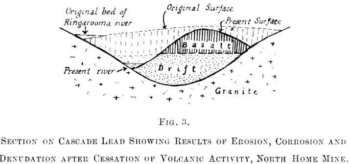
After a long period of deposition, during which the wash accumulated in the rivers and valleys to a depth of upwards of a hundred feet in places, the next important event in the geological history was the commencement of volcanic action. No craters nor fissure vents have yet been discovered, and so the actual source of the lava is not yet known. However, the basalt is found in all the valleys overlying the drifts, which have thus been protected from further denudation and preserved practically in the state in which they were discovered. The volcanic activity was not confined to a single eruption, but apparently consisted of two or more disturbances, extending over a considerable period. In the interval between successive lava flows a period of deposition took place, as proved by the presence of a thin bed of drift in the middle of the basalt. (See fig. 2.) This drift also proves that the river still occupied its original course after the first eruption, but after the final volcanic disturbance the river and tributaries were displaced and forced into other channels, in most cases on or near the contact of the basalt with the granite (Figs. 2 and 3). The lava is
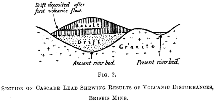
olivine basalt, and there is no essential difference between that below and above the thin seam of drift referred to. Its depth varies from about 150 ft. in the deepest part, as on the Cascade lead, down to nothing, as at the Pioneer workings. On the old
main lead at the Arba mine there is only a few feet of basalt overburden. In all cases the basalt has been subjected to extensive denudation and weathering, so that the original thickness cannot be determined. Its nature, also, has been greatly altered, for, while the heart of the hill of overburden consisted of hard columnar basalt, that nearer the surface was decomposed into a soft red soil, and between these extremes it was found in all stages of decay, commonly showing the characteristic spheroidal weathering peculiar to basalt. Meteoric waters percolating through the overburden have leached out iron, and the resulting ferruginous solutions have found their way into the drift below, which has to a small extent been converted into a hard cement of the same red-brown colour as the decomposed basalt. The remainder of the drift consists of white sand, with occasional boulders of granite shed from adjacent hillsides. Approximately horizontal layers of white pug resembling pipe-clay also occur. This material is derived from the felspathic constituents of the disintegrated granite, and its presence in the wash denotes occasional periods of tranquil sedimentation. It is hardly necessary to state that the pug contains no tin nor other heavy mineral.
Occurrence of Tin in Drifts
As already stated, the tin is found as the ore cassiterite (Sn O2), It is scattered throughout practically the whole of the drift, and occurs also in thin seams, generally horizontal or nearly so. As a rule the drift in the bottom along the gutter is the richest and the upper drift the poorest, but the values vary considerably, both along and across the lead. The ore is fairly uniform in size and is of excellent quality, the concentrates assaying over 75 % metallic tin, which means that they contain 95 % cassiterite. On the field the word “ tin ” is used for the oxide or black tin, and for shortness the same meaning will be given it in this paper.
The alluvial mines may be divided into two main groups
- Those working in the present bed of the river and its tributaries.
- Those working in the ancient bed of the lead and its tributaries.
The former are practically all worked by bucket dredging; the second group either by hydraulic dredging or hydraulic sluicing. It is the latter class of deposits with which this paper will deal. Some of them are deep, others shallow. In some cases they are buried beneath a heavy overburden, and in other instances the overburden is shallow (Arba mine), whilst a few have none at all (Pioneer mine). Obviously these varying conditions introduce differences in the methods of work apart from the modifications due to topographical and other considerations.
Preliminary Examination and Engineering Considerations
For successful working of a mine by hydraulic sluicing, apart from the questions of quantity and value of the drift, it is necessary to make sure also of the following requirements:
- (a) That the deposit is capable of being broken down and sluiced by water;
- (b) that a sufficient quantity of water is available for this and all other purposes ;
- (c) that the water can be delivered at the face at sufficient pressure, to disintegrate the drift and to work hydraulic elevators if necessary ;
- (d) that dumping areas are available for disposal of tailings or else a river of sufficiently strong current to carry away tailings at all seasons of the year;
- (e) that a suitable outlet can be got from the mine to the dump or river as the case may be ;
- (f) that any overburden to be dealt with is not of such quantity or nature as to render the cost of its removal prohibitive. Failure to investigate each one of these questions may prove very serious to the future working costs.
Another matter of the utmost importance is elevation. Very few hydraulic sluicing propositions are, carried on without the necessity of elevating at least a portion of the drift, therefore the amount and nature of the material to be elevated, as well as the height of the lift, must be determined as closely as possible, in order that the best means of accomplishing this work may be employed. Hydraulic (jet) elevators or centrifugal pumps are generally used, but other methods are sometimes adopted.
A large number of other questions must also be considered—title to land and water rights ; possibility of damage to other property by tailings, involving costly litigation and compensation; transport, labour, and climate. In an extremely cold climate the water may become frozen and thereby cause stoppage of work, or in a very wet season serious damage may occur as a consequence of floods.
Tin Deposit Valuation
This includes estimation of:
- (a.) Quantity of drift (generally stated in cubic yards).
- (b.) Value of drift (expressed as lbs. of tin oxide per cubic yard).
Where gold is present it is generally in too small a quantity to be estimated in the prospecting. If an estimate is attempted the value of the ground is given either in pence per cubic yard, grains per cubic yard, or so much gold per ton of tin.
Estimating Tin Reserves
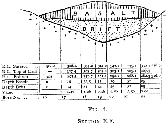
For estimating the quantity of drift and overburden in some of the principal mines the method of cross sections was adopted. Lines of bores were sunk across the lead from surface to bedrock, the interval between successive lines being 100 ft. From the data thus ascertained and the surface levels the cross sections were plotted and areas got by planimeter and checked by computation. The depth of basalt passed through in each bore was recorded, and thus separate estimates of overburden and drift were obtained. (See fig. 4.)
The difficulties of the method in practice were due to:
- Deviation of bores from the vertical.
- Irregularity of the granite bedrock.
To ensure that the bore has reached the true bottom, and not merely a boulder in the wash, it should be sunk at least 10 ft. into the bedrock. The nature of the ground itself will be the best guide as to the depth the bore should penetrate. Bores in or near the gutter are particularly liable to meet with boulders, and special care must be taken with them.
In one case where this method was employed the estimate of drift was within 4 % of the actual amount, as proved by subsequent working. The method of cross sections is universally used in estimating drift in ancient leads.
In the case of shallow deposits of greater superficial extent a plan is drawn showing the position of each bore or shaft and its depth. Where these depths are fairly uniform over a particular area the average is multiplied by the area represented, giving the volume of that portion; the sum of all such volumes is the total quantity of drift.
In cases where the bottom is uneven, either of the following methods are used:
- Contour lines are drawn at regular intervals of depth; the areas enclosed are then measured by planimeter, and the volume between every two adjacent contours is computed by multiplying the mean area by the contour interval. The use of the prismoidal formula in place of the mean area method is a refinement generally not justifiable in this class of work on account of the comparatively few points actually determined, and consequently the large amount of assumption in interpolating the remaining points and contour lines.
- The whole area is divided up by lines connecting adjacent bores or shafts. The interval between bores would depend on the funds available for prospecting purposes, the nature of the ground, and the distribution of values therein. An interval of two chains may be taken for a preliminary test, and should the results, warrant closer boring, a one-chain or half-chain interval may be used by re-boring the ground between the first series. The area having been divided into small squares, and depths recorded, the volume of all these is then computed, and this figure, together with the value per cubic yard (estimated as described later), is placed on the plan in respective divisions. This serves as a rough assay plan, and is of more use to the management during the progress of mining operations than is a contour plan, which has little practical value.
The method to be adopted in any particular case can only be decided by a careful study of the material on the spot, but generally one of the above methods, or possibly a combination of them, will be found, with perhaps certain modifications, to suit local conditions.
Estimating Value of the Tin Drift
This is perhaps the most important and most difficult problem to be solved in connection with a hydraulic mine.
The chief methods employed are:
- (a.) Face sampling.
- (b.) Tunnels or drives.
- (c.) Bores.
- (d.) Shafts.
- (e.) Combination of any two or more of the above.
- (f.) Bulk test under working conditions.
The object in each case is, of course, to treat a known quantity of drift, and weigh the tin recovered. If the sample is small, it is panned off in the ordinary prospector’s dish; if large, the working is done in a small sluice. The whole of the sample obtained should be treated, for experience has proved that small samples taken from a larger one nearly always underestimate the value.
The chief troubles in valuing are the difficulty of obtaining representative samples, owing to the irregular distribution of the values in the drift, and secondly, in determining accurately the true volume occupied by the whole sample in situ. The best method of arriving at the true size of the sample is to measure all the dirt removed in suitable boxes of known capacity. In the case of tunnels the trucks can be used for measuring, provided they are overfilled, and the excess swept off by a straight-edge drawn across the top of the truck.
Allowance must be made for the increase in bulk of the dirt after being broken out. The factor for this is best arrived at by very carefully measuring up a regular portion of the excavation and the volume of dirt it yields. A corresponding allowance is made on the volume of the whole sample.
In Face Sampling, a cylindrical vessel, such as a nail-can, of known capacity, is forced into the face at points where the value is to be determined. It is then withdrawn, and any loose sand is poured off. The contents of the can still retain the original volume they occupied in situ, and this is carefully determined. The dirt is now tipped out and re-measured in the loose state; the increase in bulk is generally expressed as so much per cent, on the original. The mean of all the separate determinations is the figure applied to larger samples or bulk tests. In very, fine wash the increase is about 20 to 25 %, in coarse gravel 30 to 40 %. These face samples are panned off separately for tin contents.
Where the depth of a deposit has been proved by a system of boring, which is the usual practice, especially in deep ground, the drift from each bore-hole is used as a sample for valuing. Its bulk should not be calculated from the dimensions of the hole, because the rubbing of the boring rods causes an enlargement in the diameter, and a corresponding increase in the amount of dirt extracted.
This increase may be quite a large proportion of the total sample—e.g., a four-inch bore worn to five inches diameter would yield 56 per cent, more dirt than the calculated amount. The only satisfactory method is to measure the dirt in a box or similar apparatus as described above.
The method of sinking shafts is often used for valuing shallow ground. It is best to sluice the whole of the dirt excavated, but sometimes samples are taken at regular intervals in depth and panned off. The results got in this way have sometimes been very close to those got by subsequent working, but the larger sample is more reliable. A difficulty with shafts is the necessity of keeping the water baled out, and in very wet ground this may prevent the shaft being carried down to bedrock.
Bulk test under working conditions requires that a plentiful supply of water is available, and also that dumping facilities exist for disposal of tailings.
Combination of Shafts, Tunnels, and Bores.—A scheme of operations comprising all the above methods was employed on the Briseis-Ringarooma workings. Tunnels were driven about 350 feet apart, and the first two connected by a branch drive. A sample was taken, each 4 feet of driving, and bores were put in 100 feet apart. 5,600 feet of driving and 2,600 feet of boring were done up to end of 1908.
Comparative Accuracy of the Different Methods
Face Sampling, unless very carefully done, does not give an accurate value of the ground. It has the advantages of cheapness and simplicity; the sample can be taken and panned off in about half an hour. The chief difficulty lies in getting a representative sample, because most stream deposits contain rich seams of tin, and there is an irresistible tendency to include too much of the rich dirt. Face sampling, in nearly every instance, has given excessively high results.
Tunnels or drives, when sampled as described, give reliable information for their particular level, but it must be remembered that certain horizons are generally richer than others, and the samples must be taken from all depths from top to bedrock.
Bores are generally sunk vertically, therefore in ground carrying rich horizontal seams of tin the bore penetrates all layers, and, theoretically, a more accurate sample should result. In practice, however, it is found that material falls in from the sides of the bore-hole, also water in the bore-hole washes fine tin down to the bottom, whence it may or may not be recovered. The sample got from a bore is rather small.
Shafts have all the advantages of bores, and the following additional points in their favour :
- (a) They give a larger sample, and, therefore, more accurate value ;
- (b) the size of the excavation allows of a thorough inspection of the ground at all depths, thug giving more exact information on the nature of the ground;
- (c) if desired, fresh samples can be taken at any depth by sampling the sides of the shaft, provided, of course, that the shaft is not in running or very wet ground.
Generally shafts cost more than bores, and the expense of sinking a sufficient number of them to thoroughly test a deposit may be prohibitive, and for this reason boring is the usual practice. In the writer’s opinion a few shafts should always be sunk in conjunction with a boring scheme, both as a check on the values and to give more accurate information as to the nature of the wash. In several cases boring gave a very close approximation to the actual working results, but in other cases the results were ridiculously high, and in one or two other instances rather low. However honestly and carefully the work be done, values as got by boring must always be accepted with caution.
As showing the advantage of large over small samples, the following figures are significant:
Case I.—All the dirt taken from a drive was treated in a sluice; as an alternative test a smaller sample was got by taking a shovelful from each truck. The result showed that the small sample gave only 53 % of the bulk test.
Case II.—Bores were sunk in drift, and shafts were then sunk in the same locality. The bores gave a value of 2.16 lbs. of tin per cubic yard, while the shafts gave 4.1 lbs. —i.e., the bores gave only 53 % of the value given by shafts in the same spot.
Case III.—Twelve blind shafts were sunk below a tunnel, and bores were put down on the same sites. Without exception the result of the bore was less than that yielded by the shaft.
Case IV.— On a gold-dredging proposition the ground was bored and then dredged. The bores gave only 77 % of the dredge returns. In this case, however, the ground was worth only 1½ grains per cubic yard, and the bores gave 1.15 grains, a discrepancy of about one-third of a grain per cubic yard.
The result of these tests seems to show that bores have a tendency to underestimate the value, also that small samples taken from larger ones in the way described cannot be relied upon.
Before leaving this portion of the subject a method used with some success on gold-dredging propositions in Austria may be worth mentioning on account of its application on a fairly large scale, though in a modified form, in Victoria. Shafts are sunk to bedrock, and samples taken are panned off, the number of colours of gold and total weight being recorded, in each case. A table is then drawn up showing the average number of colours per dish at the various shafts. A number of bulk tests (50 to 100 cubic yards) are treated from the localities of the shafts, and the actual value entered opposite the previous result. In Austria it was found that the two values bore a fairly definite relation to one another. In one case in Victoria the ground at the poorest bore gave the highest dredge return, the bore having evidently bottomed on a blank in good average ground.
Tin Mining begin with Removal of Overburden
In the geological notes earlier in the paper it was stated that volcanic disturbances had taken place since the laying down of the drifts, and that these deposits had been completely buried by the lava or basalt. It is obvious, therefore, that this basalt must be removed before the underlying alluvia can be worked on a wholesale scale.
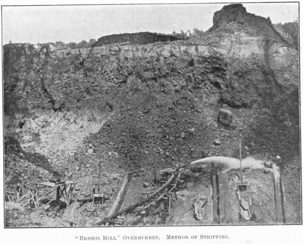
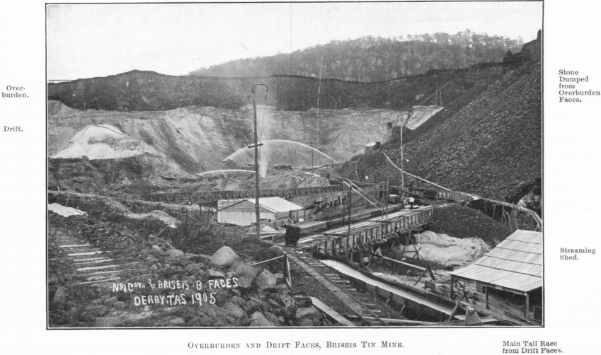
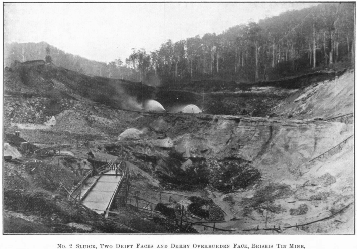
Some of the mines are fortunate in having no overburden to remove, and those that have only a few feet in thickness generally treat it through the tin faces with the drift. But the companies operating on the Cascade lead have had a very heavy task to perform. Here the height of overburden above the drift was 150 ft. in places, and the core of the hill was hard columnar basalt. The Briseis company alone has removed mostly by water about 4,500,000 cubic yards of overburden and drift. To accomplish this a large amount of water is used; for two consecutive years the average quantity available at the mine was 30,000,000 gallons a day.
The overburden was worked in benches, the height being too great to be safely worked as one face, and also because by this method the stone removed from the top benches could be dumped on the high ground adjoining the hill, thereby allowing the lower dumping areas to be reserved for the bottom bench and for the tailings from drift faces. The top benches having been entirely removed, and also a portion of the bottom benches, these are worked simultaneously with the drift faces, but kept sufficiently ahead of them to give room for pipe columns, tail races, truck roads, &c., and to prevent any overburden getting down into the tin faces should a heavy fall take place. The direction of advance is up the lead, so that the main tail races flow in the same direction as the natural grade of the lead.
Water for working the overburden is brought from the Ringarooma and Cascade races down 20-in. pipe columns, a branch going to each nozzle or “ gun.” A universal joint of the ball and socket type at the base of the nozzle enables the nozzleman to command any part of the face. A set of interchangeable brass tips of varying sizes is provided, and the quantity of water used is regulated by the size of tip employed. They vary in diameter from 3 to 7¾ in., advancing by ½ in.
The method of working is known locally as “ falling ” and “ washing out.” During falling one of the smaller tips, commonly the 4½-in., is used on the nozzle, and the water is directed against the bottom of the face, which is gradually undermined. Then the surface of the ground above the face is seen to be cracked along the top several feet from the edge, and small portions fall as a warning. The water is kept on, and after a little time the whole of the undermined portion comes down and lies in a broken heap at the bottom of the face.
When the ground is too hard to be felled quickly in this way, it sometimes becomes advantageous to use explosives for the breaking down. 3-in. bores are sunk from the top, and other holes are put into the face from below. The holes are then charged and fired, much time being saved in this way. Explosives used are gelignite and blasting powder; the charge, of course, varies—10 kegs of blasting powder are occasionally used in one hole. This shatters or “ shakes up ” the basalt, and water easily brings it down.
The operation known as “ washing out ” is then begun, and a larger quantity of water is generally brought into use. It is kept confined in the paddock by wing-boards. The softest portion of the overburden forms with the water a thick, heavy “ slurry,” which assists greatly in removing the larger rounded lumps of less decomposed basalt. Some of the stones removed in this manner weigh nearly two hundredweight. Two or three men with rakes keep the race clear, and prevent the water in the paddock from spreading and thereby losing its power. One man is employed on the nozzle and one on the dump. When the finer dirt has been washed out the water is turned off and used elsewhere. The material now remaining in the face includes a large proportion of partly decomposed basalt, which is broken by picks and washed out in the ordinary way. The small proportion still left is removed by trucking, very large stones being broken by explosives into convenient size for handling.
The tail-races are of special design (fig. 5).
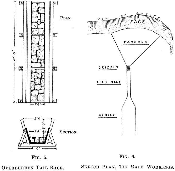
The cross-section shown has been adopted as that combining the greatest capacity with cheapness and simplicity of construction. The race is built up in sections, each 12 ft. long, and is paved with columnar basalt. Its cost, including paving, is about £8 per chain.
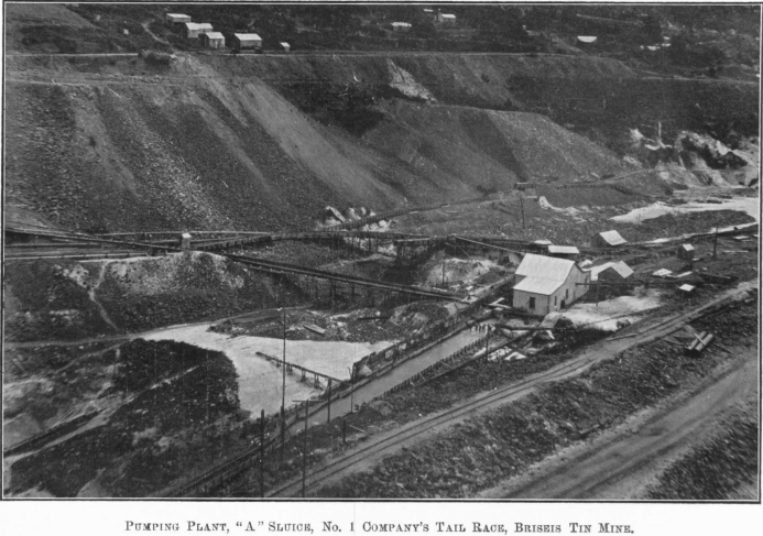
When a wide face is being worked, branch races are carried from the main race well into the face, so that there may be no difficulty in getting the stones away. (See Plate I.). The grade is 1 ft. 9 in. per chain (about 1 in 37½), and the quantity of water that can be used with safety is about seventy sluice-heads. The paddock is rim on a steeper grade than the tail-race.
Dumping
The Tasmanian mining regulations limit the size of stones that may be discharged into a river to a diameter of 2 in. To separate the large stones the tail-race discharges on to a large grizzly, the oversize being retained on the dump, the undersize and water sent to the river. In another case the tail-race discharges on to the surface of the dump, and the water is spread, causing the heavier material to settle, the light stuff passing with the water to the river. A retaining wall of scrub is built up as the dump rises.
The duty of the water, or, in other words, the number of gallons required per cubic yard removed depends on the following conditions :—
- Nature of the material being dealt with.
- Quantity of water used (within limits).
- Pressure of the water.
- Design and grade of tail-races.
- Ease of getting material into race.
- Care and attention on the part of nozzleman and rakers.
The actual quantity removed annually is over half a million cubic yards. In one year 198,162 cubic yards were removed from one hill, the water used being = 7,509 sluice-head days. The duty is therefore 8,184 gallons per cubic yard. Another way of expressing the same result is 26.39 cubic yards removed per sluice-head per day.
In another face 321,100 cubic yards were shifted, the water being equivalent to 11,630 sluice-head days, giving a duty of 27.61 cubic yards per sluice-head per day. In the latter case some of the water used was at a greater pressure than in the former. The mean of these results is
27.00 cubic yards per sluice-head per day on a tail-race grade of 1 ft. 9 in. per chain.
The grade must always be stated, the amount of overburden removed being directly proportional to the steepness of the tail-race.
If the fall be. 1 ft. in 6 ft., then the ratio of overburden to water in the tail-race is 1 : G (nearly). In the above case the grade of 1 ft. 9 in. per chain (1¾ in 66) is equal to 1 in 37.7, so, theoretically, 37.7 parts of water would remove 1 part of basalt.
1 sluice-head = 24 cubic feet of water per min.
= 1,280 cubic yards per day.
So on the above grade the theoretical quantity that should be removed per sluice-head of water per day is
1,280 x 1/37.7 = 34 cubic yards.
The result of a year’s work was (as worked out above) 27 cubic yards, therefore the ratio of actual to theoretical volume is
27/34 or .80,
which may be said to represent the efficiency realized.
During the period referred to only 2 % of the total overburden removed required to be trucked. With a higher proportion of trucking the efficiency may suffer, owing to interruptions and other causes.
As a general formula the cubic yards of overburden (B) removed per day by S sluice-heads of water, the tail-race having a fall of 1 ft. in G, would be
B = S x 1,280 x 1/G x E = 1,280 S E/G
where E is the efficiency.
Taking the .80 value as worked out in the above case for E,
B = 1,024 S/G
The formula is not given as a mathematically accurate law, but, under the conditions mentioned, it furnishes a sufficiently close approximation for most ordinary purposes.
Sluicing the Tin Drift
The drift is worked in benches, similarly to the overburden. Apart from the convenience, this method possesses the advantage that only the portion of the drift below the level of the gravitation tail-race has to be elevated, which means economy of pressure water, and a saving of time, which is occasionally lost owing to stoppages of elevators for repairs, &c.
Briefly, the work is to wash down the drift with water, separate the cement, stones, &c., and allowing the water and drift to pass through feed-race, sluice, and tail-race to the dump. Most of the tin remains in the paddock. The lower drift is lifted by means of hydraulic elevators. Where two benches on different levels are close enough, they are commonly worked in conjunction, the drift from both passing through one sluice on the upper level. The thick feed from the upper face mixing with thin feed from lower (due to dilution by elevator water) gives the correct mixture of sand and water for the sluice.
In cases where a bottom face is worked singly, the mixture with elevator water is too dilute for a sluice of the above type. One of the three following methods may here be adopted :—
1st.—Run as an ordinary sluice on the lower level and elevate the tailings.
2nd.—Elevate the “ feed,” and, where dirt is scarce, work with a V settler at the head of the sluice, returning the overflow for feed water to the same face.
3rd.—Work on a different principle with high ripples.
The disadvantages :—First method.—In case of elevator stopping, the sluice becomes flooded unless all water is turned off at once. Second method.—There is not much pressure in the feed-water, and a more skilful sluiceman is required. On the other hand, it is the most economical method (as regards water required) where dirt is scarce.
In commencing operations on a drift face, a portion of the floor of the face is boarded off to form a paddock, roughly triangular in shape. All drift has to run over this area, and most of the tin is deposited here, water and sand passing on to the sluice. The cement already referred to is broken by explosives and spalled into convenient size for handling. Then, together with any pug and any stones left from overburden operations, it is thoroughly washed to remove adhering tin, and finally trucked out and dumped. Any odd cement fragments, stones, &c., still left are caught on a grizzly placed in the feed-race for the purpose. The necessity of removing these is apparent. The heavy stones and cement would remain in the tin concentrates, while pug, being of a sticky nature when wet, is liable to carry tin into the tailings.
Design and Construction of a Tin Recovery Sluice
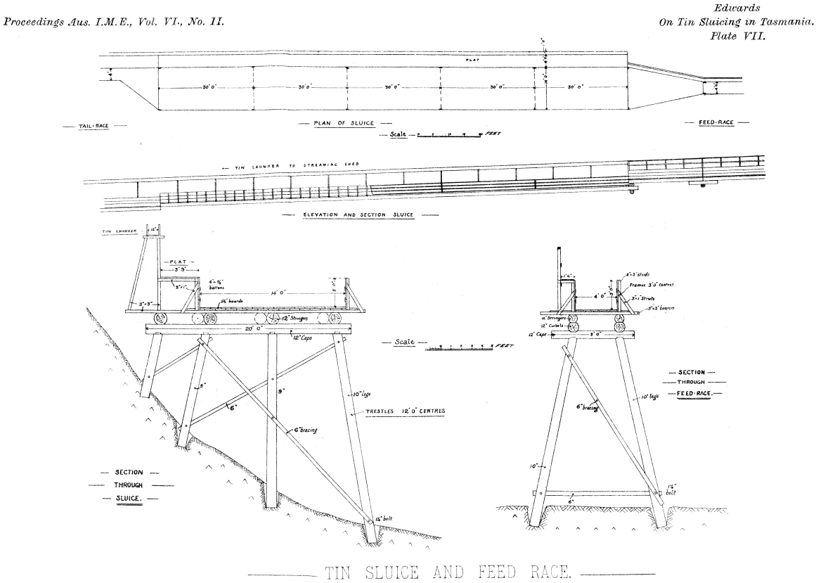
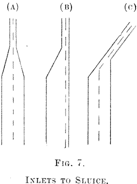
The dimensions are—width, 8 to 14 ft.; length, 132 to 180 ft., laid down on a grade of 2 ft. 3 in. per chain. The sluice is built in 4 to 6 sections, each 24 to 30 ft. long. At the tail of each section ripples are provided. They are made of 3 in. x 2 in. and 3 in. x 1½ in. hardwood, corresponding in length to the width of the sluice. Timber is used throughout in the construction ; bearers and studs are of 3 in. x 3 in.; chocks and struts, 3 in. x 1 in.; boards for bottom and sides, 12 in. x 1½ in.; battens, 4 in. x ¾ in. and 5 in. x 1 in. The sluice should be perfectly level from side to side. It may be supported on trestling, as shown in Plate VII., or built on the ground, which is formed to the requirements of the case. Feed-races are built exactly like the sluice, except that they are narrower, being only three or four feet wide. The depth of both feed-race and sluice is generally three feet. The change in width is made gradual, the best arrangement being that shown in Fig. 7 (a), where the centres of feed-race and sluice coincide. In the other cases there is a tendency towards an accumulation of tin on one side of the sluice, which causes inconvenience in working, especially during the clean-up. Ripples are used in the feed-race for the same purpose as in the sluice. The distribution of the feed across the sluice is regulated by baffle boards placed at the junction of the feed-race and sluice. At this place there is generally a drop of a foot or two.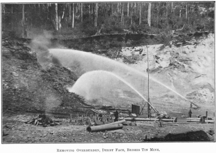
At the commencement of a run only one or two ripples are put in the sluice at each section, just sufficient to provide a sand bottom to hold any tin that may reach the sluice. As work proceeds, tin and drift accumulate in the paddock and the grade
becomes steeper accordingly. The water then has a greater carrying capacity, and not only is fine tin liable to be carried down the race, but also the sand covering the tin in feed-race is carried away and when tin is exposed to the water it is transported to the sluice.
To restore the original grade a ripple must be put in the sluice at each section, in this way causing the sluice to rise correspondingly with the paddock. At the same time the ripples prevent any tin being carried past them, and also hold back sufficient sand to cover what tin is already in the sluice. Work continues, the paddock rising slowly all the time, and the sluice being rippled up at the same rate until in a fortnight or so it is nearly full; it is then “run down,” the tin is sunk under the drift, a couple of inches of sand being left to protect it from the water. Sluicing is re-commenced in the face, and operations are repeated as before.
The property on which the separation of tin and sand depends is specific gravity. The “ feed ” (water and sand) on entering the sluice spreads out into a thin layer and flows through the sluice at a velocity just sufficient to carry the sand in suspension without washing away any particles of tin, which remain in the sluice, and eventually settle on to the working bottom of sand. This sand bottom must be kept loose and rough, in order that metallic particles may not be rolled along and washed away in the tailings. To keep it in good order the sluiceman constantly forks it, causing the tin to sink below the surface where it is then safe. This loosening of the sand makes the working bottom just as loose as the bed on a jig, but there is no pulsion nor suction, the effect being more like that of quicksand.
Apart from the drift carried in suspension by the water a certain amount is moved slowly along the bottom of the stream—i.e., along the surface of the working bottom. This fact renders it important that the tin should be sunk below this region of corrosion, which should consist of tailings only. A layer of sand 1 in. thick would probably be sufficient to protect the tin, but 2 or 3 in. is the usual practice, so that if the water should from any cause form a “ gutter ” in the sluice and scour out the covering drift to a depth of an inch or so, the tin would not be exposed to the scour of the water. This “guttering” can be avoided by reasonable care. Any slight tendency towards it can be remedied by judicious use of the sluiceman’s shovel, but if the trouble appears to be permanent, a re-adjustment of the baffle boards at the head of the sluice will generally right matters. The same trouble may be to a certain extent caused through a badly constructed sluice or by bent or misshapen ripples.
Once a good set of conditions is established—i.e., as regards quantity of water, grade of paddock, feed-race and sluice, quantity of drift or feed, &c., the aim is to keep as near to this as possible.
If this can be done the paddock race and sluice rise at a uniform rate, and the sluice is rippled up as required. The quantity of water used depends on the width of sluice; 1 to 1½ sluice-heads of water per foot of width is the proper quantity, according to coarseness of tin.
It is often a difficult matter to keep the feed so regular, especially when working in a cementy or stony face. A diminu-
tion in the quantity of drift being carried by water results in corrosion of the surface of the bed. In time the water would “ cut down ” to the bare tin, and loss of metal would result. If a sufficient and regular feed cannot be maintained the ripples must be put in at each section of the sluice. They form a series of dams which fill with water and hold back any tin which may be escaping. The feed-water now coming from the face flows over the surface of these dams, the still water held by the ripples protecting the tin in the same way as did the sand-covering. Any drift brought with the feed-water settles as soon as it reaches dead water, and when sufficient has been collected to renew the sand- covering the upper ripples may be one by one withdrawn.
The reverse trouble-viz., too thick a feed—may possibly cause loss of tin through its failure to separate out, but in any case it causes excessive deposition of sand in the feed-race and sluice which necessitates the latter being “run down” more often than really necessary, requiring extra labour and loss of sluicing time.
This “ running down” process is a concentration of the sluice contents into a thinner but richer bed, so as to reduce the level in the sluice and restore a suitable grade. The operation is performed by three to five men, according to the width of the race. The feed being turned off, clean water—“ head water is admitted at the head of the sluice, and the men, working in a line, shovel the dirt and turn it over, throwing it up stream. The water carries away light tailings, and the level is thus gradually lowered. A ripple is taken out whenever necessary, and the process continued until the tin is fairly black. This is then covered by a layer of sand, and sluicing is recommenced in the ordinary way.
Sluice Tail Water
After passing through the sluice the tailings drop into a tail-race constructed on a flatter grade than the sluice, and are carried away to the dump. The quantity of water used in sluicing is insufficient for this purpose, on account of the lessened grade, and an additional supply, called tail water, is necessary. Its quantity depends on the relative proportions of sand and water in the sluicing mixture, and on the relative grades and widths of sluice and tail-race. The steeper the grade of the tail-race the less tail water is required, but, on the other hand, the lower will be the level of its outlet, and the capacity of the dump is correspondingly reduced. The selection of a tail-race grade must be decided in each particular case according to the local conditions. The considerations involved are:
(a.) Dumping space (volume) required.
(b.) Dumping areas available.
(c.) Quantity of water (if any) available for use as tail water.
(d.) Cost of elevating or stacking tailings if necessary, and amount requiring elevating.
Water Measurements on the Tin Mines
The water supply from the company’s various races is distributed over a dozen or more overburden and drift faces, also to the water turbines of the tailings pumping plant and to the electric lighting Pelton wheels. It is necessary to record the amount supplied to each particular machine or nozzle—firstly, in order that the working costs of each face and cost of power may be arrived at; secondly, to check the efficiencies, and thirdly to warn the management of any leakages along the race or waste at the mine.
The discharge of nozzles and hydraulic elevators having circular orifices are taken simply as the product of the jet area (A), the mean jet velocity (V), and a co-efficient of discharge (c), or, expressed symbolically:
The water used W = c A V.
Experience has proved c = .94.
Substituting this value in the equation, and expressing A = π d²/4 x 144 and V = √2 g h = √64 h,
where d is the diameter of the tip in inches, and h the pressure head in feet at the jet, the formula becomes
W = .94 x π d²/4 x 144 x √64 h
The quantities used are so large that the amounts expressed, either in cubic feet or gallons, would be too cumbersome for ordinary records, and very inconvenient for mining parlance. The Tasmanian sluice-head is universally adopted as the unit. Converted into sluice-heads the above expression becomes—
W = .94 x π d²/4 x 144 x √64 h x 60/24
= .1025 d² √h sluice-heads.
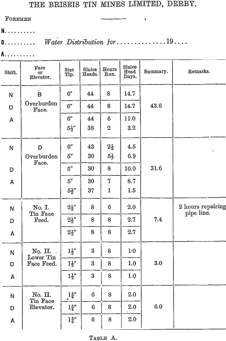
Gauge cocks are provided, at each nozzle, and the pressure in feet of water is read every shift, and at any change in the size of tip in use; the diameter of each tip is stamped on it, so the discharge at any time is easily ascertained. To simplify the work a table is supplied to shift foremen and others showing the discharge of each size tip on the mine for all pressures up to the maximum obtainable.
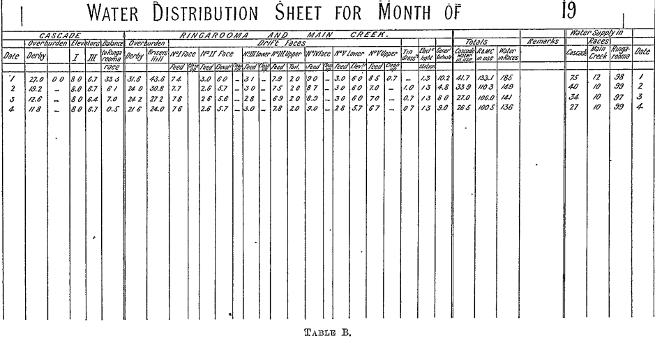
The method of recording these quantities is best illustrated by reference to the printed forms employed on the mine. (Table A, page 144.) shows the variation (if any) during the twenty-four hours. The figure in the summary column represents the average for the three shifts, and this amount is entered on the monthly sheet, (Table B, page 145.)
Water in the races is measured by gauge boxes of the usual type, as described in Mr. Champion’s paper on “ The Briseis Water Race.” The quantity in each race is placed under its proper heading on the monthly statement; the total supply in races is tabulated and checked against the total in use. Under normal conditions the discrepancy is only about 1 per cent., and can often be accounted for.
A summary of the whole month’s consumption at each face is then made, and from this the average daily distribution for the period is drawn up.
Measurement of Drift and Overburden Removed
The method employed for monthly or quarterly measurements is that of horizontal contours. Points are carefully selected on the face, and, with the theodolite set up at a convenient known point, the bearing, angle of elevation (or depression), and distance of each point in the face are read. For the distances stadia measurements are taken. With this information the true, horizontal distances and reduced levels are found and plotted on a plan of the workings. Points for contour lines are interpolated between those taken in the actual survey, and a system of contour lines is drawn in at 5-feet intervals.
The corresponding lines for the previous period are left on the plan, and the area removed at each level is measured by a planimeter. The areas and depths being known, the rest is simply a matter of multiplication.
After an extended period of regular measurements of water used and drift removed by it, also the grades on which the race was run at different times, an investigation was made into the relationship existing between these quantities. It was found that the nature of the material being dealt with had such an important bearing on the results that a co-efficient had to be introduced to make a formula at all possible.
Calling this k
and g the average grade of sluice throughout the run,
D the cubic-yards of drift removed,
W the cubic, yards of water used,
then
D = kW sin. g.
One sluice-head being equal to 1,280 cubic yards per day, the amount removed daily becomes
D = 1,280 kS sin. g.
S being the average number of sluice-heads in use.
The value of k varies so widely that the formula can only be used, and then with caution, after some experience of the ground
being worked. For very clean, loose drift, free from cement, pug, and granite boulders, the value of k approaches very nearly to 1. In decomposed basalt capable of being removed almost entirely by water, k = .75 to .80.
In cementy or stony drift faces personal experience is the only guide, but so long as the drift is reasonably clean a fairly good approximation may be expected.
The following example is from actual practice. In this case the drift contained a little pug, but otherwise was clean, so the value assigned to k was .95. The water used during the period was equivalent to 900 sluice-head days, and the average grade of the sluice was 2 ft. 9 in. per chain (1 in 24). Substituting these values in the formula,
D = 1,280 x .95 x 900 x 1/24
= 45,600 cubic yards.
The amount removed was estimated by survey to be 46,100 cubic yards, a difference of only about 1 %, which is probably within the limits of accuracy of the data used.
Cleaning Up
The work of cleaning up consists in recovering from the paddock, feed-race, and sluice, the tin and gold which has become concentrated there. The first operation is to “ run down ” the sluice, as described above. This concentrates the tin, which is skimmed off and thrown out of the sluice on to the plat (see Plate VII.). During skimming the water is turned off. When the sluice has been practically cleaned out the feed-race is “ run in ; ” clean water is admitted at the head of the race, and men assist by shovelling the tin with the current. The sluice being empty, the grade of the feed-race becomes much steeper, and the sand and tin travel much faster than during ordinary sluicing. Ripples must be put in the sluice to hold the tin. When sufficient material is in the sluice it is “ run down ” again and skimmed as before, and the operation continued until the feed-race is cleaned out. Lastly, the paddock is “ run in ” in the same way, clean water with practically no pressure being drawn from the nozzle, through pipes if necessary. In order to hasten the operation the water is kept confined between two rows of wing-boards A B (fig. 8), and, when the sand inside
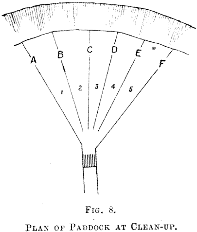
area 1 has been washed away, the boards A are shifted to a parallel position C alongside the last. The area 2 is then treated in the same manner as 1, and then boards B are moved to D. This is continued until the whole of the paddock has been treated and nearly all the sand removed. The tin mostly has remained behind, and it is skimmed and wheeled in barrows to the feed-race, whence it is carried by water to the sluice. Here it goes through the running down process, and when tin is skimmed off and thrown out for next treatment, work is recommenced on the face.
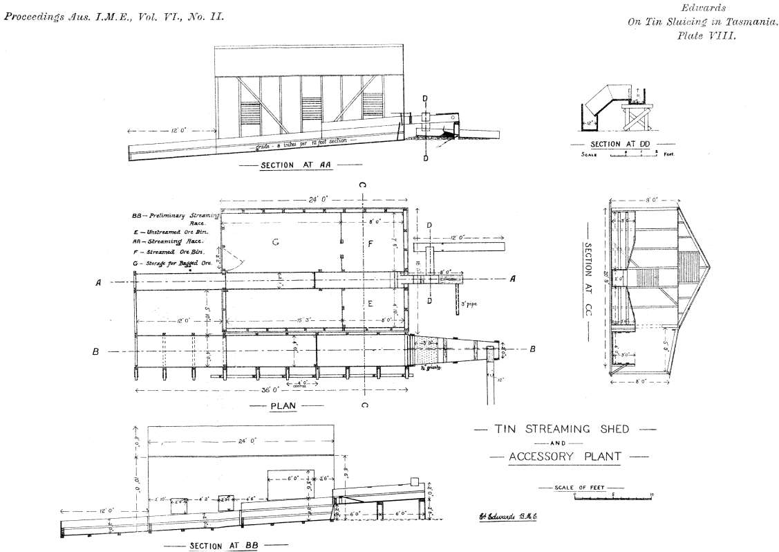
The tin on the plat, although often very clean, still contains sufficient sand and other impurities to make further treatment necessary before smelting. This operation, well known as streaming, is conducted in special streaming sheds (see Plate VIII.), and the tin is conducted there through small wooden launders 12 in. wide in which a current of water flows continuously. At some
convenient place in this tin launder the gold-saving appliances are provided. These will be described later.
On reaching the sheds, the tin undergoes a preliminary cleaning in a small sluice outside the shed. This is 4 ft. wide, 24 ft. long, and in two sections (see plan, Plate VIII.). The concentrates from this are ready for the final operation.
Streaming
It is conducted in a small race 2 ft. wide, 24 ft. long,, divided into two sections, head and tail, and laid down on a grade of 8 in. per 12-ft. section (1 in 18). Water is laid on at the head of the streaming race, and admitted by a door in the launder. About a hundredweight of tin is streamed at a time. The tin is put in the race and water admitted. Then the streamer, who must be a very skilful man, shovels the tin very rapidly up the race against the water current. After a minute or so the water is stopped, and the tin at the head of the streaming race is thrown out and allowed to drain before being bagged. The rest of the material accumulates at the tail of the section against the ripples. As this may contain a little fine tin, it is retreated, and tailings are then stacked outside. They contain, besides heavy sand, topazes, sapphires, titaniferous iron, and tourmaline (known locally as “ blackjack ”).
After streamed tin has drained it is bagged in the sheds, each bag holding 1 cwt. Moisture determinations are made daily, 112 grams weight of the drained tin being dried and reweighed. The loss in weight is the number of grams of moisture in 112, which is equivalent to lbs. per hundredweight, and in weighing the ore into cwt. bags a corresponding allowance is made.
Reviewing the above operations, it will be seen that the concentration is done in four stages. Taking a case where the ground averages 5 lbs. per cubic yard, this is less than 0.1 %.
1st Concentration.—The paddock would be, say, 1 to 3 %.
2nd Concentration.—The sluice concentrates, 60 or 70 % down to 30 at tail.
3rd Concentration.—The preliminary streaming, over 70 % .
4th Concentration.—The final streamed tin, 75 %.
Returning to the gold sluice already mentioned, this is about 3 feet wide and 10 or 12 feet long, set on a steep grade, 1 in 4 or 1 in 6. It is made of wood, with a coarse screen of perforated metal plate at the head to separate any heavy foreign matter. The gold is saved on cocoanut matting, of which there are five or six sections. Most of the tin passes on to the streaming shed, but a little remains on the matting with the gold. No mercury is used in the sluice. The gold is practically all recovered from the first and second mattings, which are taken out and washed in troughs. The remaining mattings are moved up towards the head of the gold sluice, and those just cleaned are put in at the tail end for the next clean up. The gold concentrate, after being freed from small stones and other miscellaneous articles, is treated in an ordinary prospector’s dish. Mercury is now added, and the whole thoroughly mixed; some boiling water is poured in to keep the mercury lively and prevent the mass from “caking.” The whole contents must be thoroughly mixed until amalgamation is complete. This can be seen by inspection of the concentrates. When no particles of free gold can be seen, and only tin and amalgam are visible, it is safe to give about five minutes further mixing and then pan off the amalgam. The tailings are panned off again to recover any amalgam lost in the first treatment, and about one or two per cent, may be recovered here. The amalgam is squeezed in chamois cloths, retorted and smelted. The tailings, which are chiefly black tin, are run once again through the gold sluice, and thence to the streaming shed.
Costs
Hydraulic Sluicing of Drift
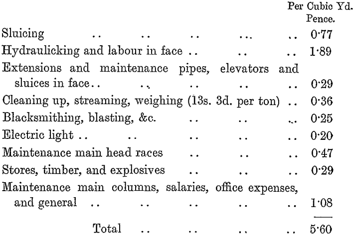
Cost, including all operations to the sacking of concentrates, 5½d. to 6½-d. per cubic yard.
During one annual period the cost of each portion of the work was as follows:
Dredging
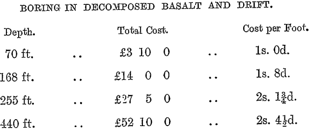
The cost varies very widely with the conditions. Given a fairly regular water supply, the suction dredges work at 6d. to 9d. per cubic yard. When the water has to be pumped to the mine, or when the supply is intermittent, the cost increases. Under very adverse conditions as regards water supply, ground being treated, and dumping areas, the cost per cubic yard on one of the smaller plants was nearly two shillings.
The Tasmanian bucket dredges as a rule have not made their costs available. In the Bright district, Victoria, many are working on gold at 2½d. to 4d. per cubic yard, and one of the large-capacity dredges recently installed is reported to be working at less than 2d.
None of the Tasmanian dredges are working as cheaply as this, inherent difficulties in the ground and unfavourable climatic conditions being mainly responsible for the difference.