Table of Contents
Undercut-and-fill- mining is a method developed by the International Nickel Company to deal with abnormal-pillar mining conditions at one of its mines. Results have been such -that its use has been extended to normal pillar recovery operations in other mines of the Company as a replacement for conventional square-set pillar mining. It is anticipated that the method will also largely replace square-set stoping at INCo mines, especially for mining at deep horizons.
General Description of the Method
Undercut-and-fill is a method of extracting a block of ore by mining successive layers, or cuts, working from the top down. After a slice of ore is completely mined out, continuous laminated timber stringers are constructed along the sides and for the full length of the cut. Logs are laid across the stringers to form a timber mat and the opening is then tightly filled with .water-borne sand fill.
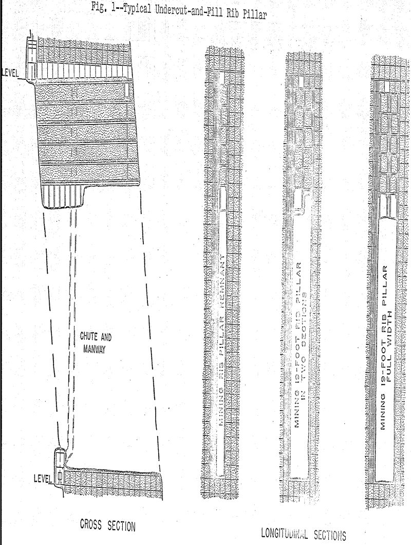
Rib pillars mined by undercut-and-fill are either full pillar width, 19 feet, or are the remnants left after an overhand square-set slice has been mined in the pillar. Depending on local conditions a 19-foot pillar is either mined full width , or the cut is divided into two transverse sections. In the latter case, the first section is mined and filled before the section beside it is mined. When both are completed the operation is then repeated on the next lower cut.
The first cut is mined 10 feet high and is timbered with standard 5-½-foot square sets. The timber is positioned so that stringers can be built in the required location. Mining is started at the chute opening and advances to the end of the cut in a:series of 6-foot blasts.
Timbering
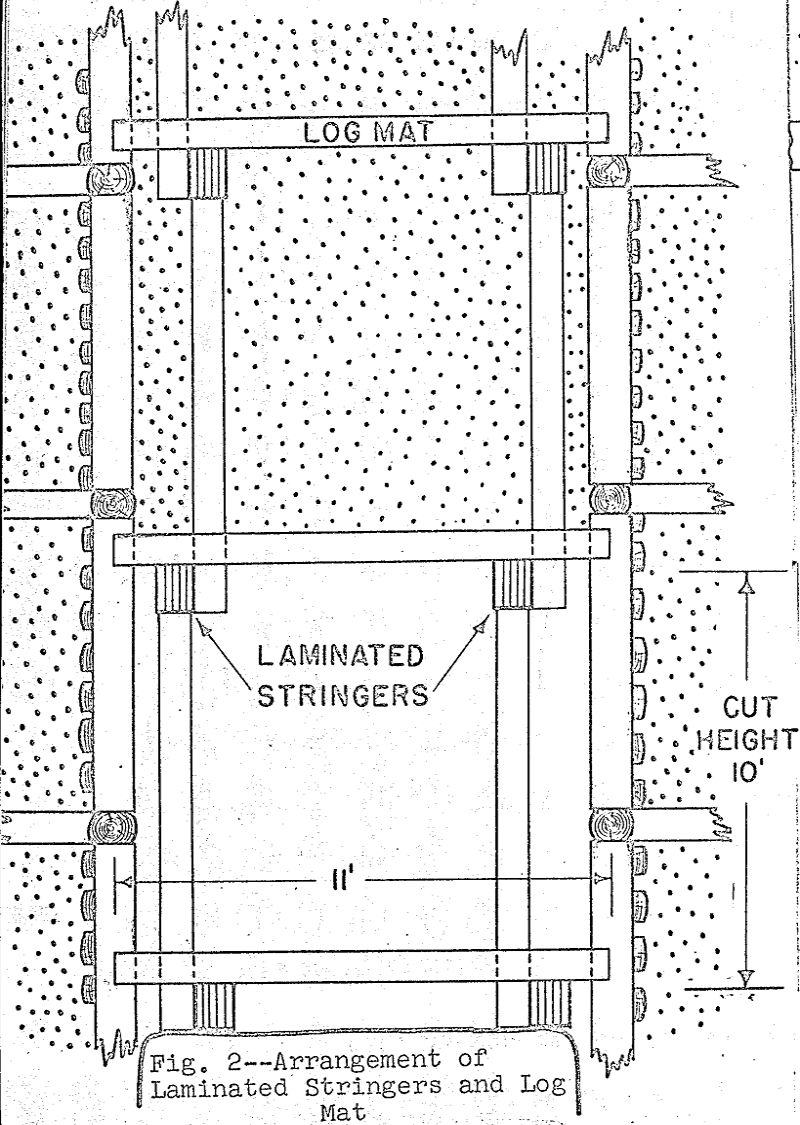
The timbering system developed for undercut-and-fill mining is simple, repetitive and makes use of low cost saw logs rather than the framed and dimensioned timber required for square-setting. The basic requirement of a mat to support the fill mass overhead is met by building continuous laminated stringers on the floor of the working place and then laying a transverse mat of logs on the stringers.
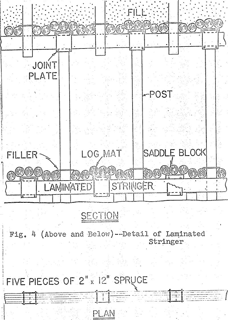
The planks used in stringer construction are No. 1 Western spruce dressed 1-¾ x 11-¾ inch, 11 feet long. Stringers, five planks in width with alternate planks staggered on 5-½-foot centres, are constructed on the floor of the working place in the required location.
At the joints in the beam 14 x 16 inch steel plates 5/16 inch thick are installed on each side of the stringer. The plates are bolted together with four ¾ x 10-inch carriage bolts two bolts above the top of the stringer and two bolts below the bottom. Bolts are tightened with an air-operated impact wrench.
Ore Removal
In undercut-and-fill stoping, 15 h.p. double drum air-operated slushers and 42-inch toothed scrapers are used for ore removal. The broken ore is scraped to a chute located at the footwall end of a cut. Long cuts are illuminated with air-operated lights.
Toothed scrapers proved most effective for scraping from a muckpile steeply banked against the face on the rough, raw bottom of the cut. The scraper used has five teeth on each, edge of a reversible back plate. After the teeth on one lip have been worn down the back plate is reversed. When the teeth on both lips are worn out the back plate is returned to surface, for reconditioning.
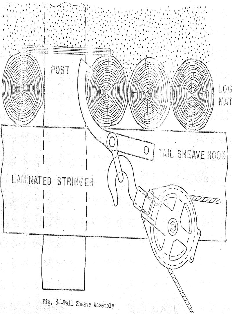
Because of the mat overhead it is not possible to use a chain and ring attachment for anchoring the tail sheave, nor is it possible because of ground conditions to set an eye bolt at the face. Various devices for anchoring the tail sheave were tried.
Drilling and Blasting
Drilling is done with airleg drills and 7/8-inch tungsten carbide insert steel (Figure 9). Some difficulty has been experienced in drilling holes in broken ground and experimental work is now in progress to determine the effectiveness of an “auger” type steel combined with 1-3/8-inch detachable four-wing bits with tungsten carbide inserts. The 3 percent nickel alloy drill steel is rolled as a circular section with two raised ribs 180° apart.
Two methods of applying undercut-and-fill mining have been developed for recovering horizontal pillars.
In the first, a slusher drift is driven from an ore pass in the footwall 25 feet below the pillar. Boxholes and manways are driven from the slusher drift to the bottom of the pillar. Raises are then driven to the level above and square-set slots are mined from bottom to top of the pillar. The chutes and manways required for mining the pillar by undercut-and-fill are established in these slots (Figure 11).
In the second method an existing chute opening, located in the mined-out area below the pillar, is used to eliminate the footwall development. A short ore pass is driven from the top of this chute to the top of the horizontal pillar. A longitudinal slusher drift is then driven from the ore pass to ends of the horizontal pillar at the elevation of the top cut of the pillar.