
Every constructing engineer and designer knows how often it is desirable to provide a speed-adjustment between parts of a machine performing different functions, or between a prime mover and the devices to which it furnishes power, and how bulky and unsatisfactory are most of the methods by which the result is usually accomplished. Of course the step-pulley is the most simple and generally used. It requires:
- parallelism of shafts;
- a considerable distance between centers; and
- a cessation of power during the change from one speed to another.
Add to this the necessity for careful design in order to obtain equal belt-tension for all positions; the weight and bulk required for a wide range; and the operative’s positive conviction that better results could be obtained at a speed intermediate between those furnished by two successive steps, and we begin to realize the mechanical shortcomings of this old and familiar friend. The hundred and one other devices, patented and otherwise, for accomplishing similar results, present other objections of varying importance, which need not be discussed here.
Without pretending to overcome these entirely, and indeed without claiming absolute novelty, a recent invention of Mr. E. F. Gordon, of Dover, N. H., has seemed to the writer to offer such advantages in flexibility and range of application as to merit a more extended study and use than can be given in his own work, to which it is being applied as rapidly as opportunity permits.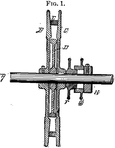
It is placed before the members of the Institute, not only to bring out an expression of opinion as to its limitations, but also with the hope that it will thus find opportunities for applications hitherto untried and outside the scope of operation of those at present interested in its development.
Simply stated, the device consists of a narrow pulley with a deep V-groove, split by a plane passing through the bottom of the groove, one of the two symmetrical parts so formed being fixed to the shafts, and the second being capable of adjustment so as to bring the faces of the groove nearer or farther apart. By the use of a narrow or round belt, and with faces having the proper angle, the working radius may be varied within wide limits, while a loose sheave may be inserted between the two pieces, thus combining the differential- speed principle with the equivalent of a tight-and-loose pulley.
In the illustration, Fig. 1, A is the shaft; B, C, are the two halves of the pulley ; D, is the idler; E, the belt; F, G, hand-wheels; H, a collar, fast on the shaft. By the action of the belt, B and C tend to separate from each other; and since B is fast on the shaft, A, C (which is splined on the shaft, and hence must turn with it, although free to move along it) is forced against F. The hand-wheels, F and G, are free to turn on the shaft, but may be held at rest whenever desired. The hub of one carries a male screw, and that of the other a female, so that by altering the position of one on the other, they increase or decrease the distance between the collar, H, and the half of the pulley, C, thereby allowing C to recede to a greater or less distance from B, and determining the position of the belt, E, and its consequent speed relative to that of the shaft, A. It will be evident that in this construction, when used as a driving-shaft, the belt-speed will become less and less as F is screwed into C, until C has so far receded from B as to allow the belt to drop on to the idler, P, when the driven mechanism will come to a standstill, to be gradually started again by the adjustment of F and G.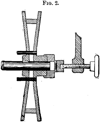
Fig. 2 shows a still simpler form, applicable when the pulley is located on the end of a shaft. In this case the loose pulley is omitted, it being assumed that only a speed-adjustment is necessary, one part of the pulley being fast on the shaft, the other free, but loosely pinned to the first so as to rotate with it, and the working-radius being determined by the adjustment of a hand-screw.
The belt may be either round or nearly square in section, though, for most of the experiments so far made, a narrow double-ply leather belt has been used, with the edge beveled to correspond with the angle of the pulley’s face.
The construction shown in Fig. 2 has recently been applied to the
feeding-rolls of a 48-inch band-re-sawing machine in a way which illustrates its simplicity and adaptation to this class of work.
Fig. 3 shows the arrangement of parts, A being the split pulley, its shaft being driven by a link-belt from a continuation of the lower band-wheel shaft, and supported by an arm, B, swinging from this as a center. The belt, C, drives the pulleys, D, D, on horizontal shafts worm-geared to the axes of the feed-rolls, the swing of the arm, B, compensating for the varying length of the belt, C, owing to changes either in position of the feed-rolls, E, with reference to the saw, or in the working-radius of A, the latter being determined by the position of a hand-screw.
The diameter of the split pulley is 12 inches, the minimum working-radius 3 inches, giving a linear speed to the surface of the feed- rolls of from 10 to 30 feet per minute. A double-ply belt, 1 inch wide, is used, and its power is such that if the stock be held firm, the slip occurs between it and the feed-rolls (four in number, all geared, 18 inches long, 3 inches in diameter), and not at the belt, as in the case of the usual style of cone-pulley employed in another machine of the same capacity.
In addition to the combination band-saw and resawing machine above-described, the variable-speed pulley has been applied to the feed-works of a wood-surfacing machine, the knives of which were 26 inches long and the bed-drop 10 inches, and to a 16-inch pattern-maker’s lathe, in the latter case replacing both the spindle and countershaft-cones.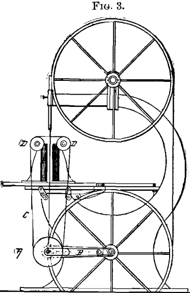
In the planer, the split-pulley was applied to an intermediate driving-shaft, from which the 4 feed-rolls were driven at any desired circumferential speed between 30 and 65 feet per minute. The belt used was two-ply, center-riveted, 1 inch wide and slightly bevelled to correspond with the face-angle of the pulley, the two parts of which were pressed together with a wedge operated by a hand-lever, and thrusting against a collar fixed upon the shaft. With a 2-inch ordinary belt, single-ply, on another machine of equal capacity, the slip is quite marked when handling heavy.stock, while with the Gordon pulley it was imperceptible under the severest possible tests.
As applied to the lathe spindle, the construction is as shown in Fig. 1, but omitting the idle sheave, while a similar split-pulley overhead automatically compensates for changes in the working radius of the spindle-pulley, one-half being fixed to the countershaft, and the other half pressed against it by a weighted lever. The pulleys in this instance were small, and the minimum and maximum speeds were in the ratio of 1 to 10. The 2 hand-wheels forming the expansion device revolve with the spindle, and by slightly checking either one by hand, or with a small leather-covered brake attached to the head-stock, any desired speed within the limits above- mentioned is almost instantly obtained. The advantage of the device in this case is principally in its convenience and the operator’s absolute control of the working speed, although the lack of slip is a noticeable feature.
It will be seen that, unlike most devices of the kind, this one does not require parallelism of the driving and driven shafts; the distance between the shafts may be varied almost at will; speed may be adjusted to a fraction of a revolution within pre-arranged limits; these limits are wider than could be secured by most other methods at an expenditure of a much greater amount of material and space; and, finally, adjustment of speed may be made while under load.