Table of Contents
The importance of controlling water inflow during shaft development has been well known to those faced with the problem. Depending on the amount, temperature, and quality of the water, the extra costs of working in wet conditions can easily be several times that for the same work under dry conditions. I have heard estimates of cost increases from 25 percent to 300 percent. The actual cost increase can be controlled if the water inflow is expected and if adequate control measures are employed prior to encountering the water.
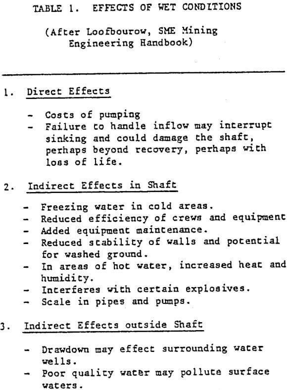
Table 1 lists some of the problems that can be associated with working under wet conditions. The more obvious of these effects are considered direct, that is directly associated with pumping or controlling water inflow. Usually most mining projects will have taken these into account at feasibility stage. However, there are also indirect effects which are not always fully accounted for during the early feasibility stages. These include such items as muddy conditions, freezing of water in the shafts, added equipment maintenance, reduction in ground stability and washed ground, problems with explosives and scaling of pipes. These are indirect effects which occur within the shaft itself. Others may occur outside the shaft area including the effect on surrounding water users of drawing down local water tables during pumping from the shaft and the discharge of potentially poor quality water to surface drainages.
Assessing the Location & Amount of Water
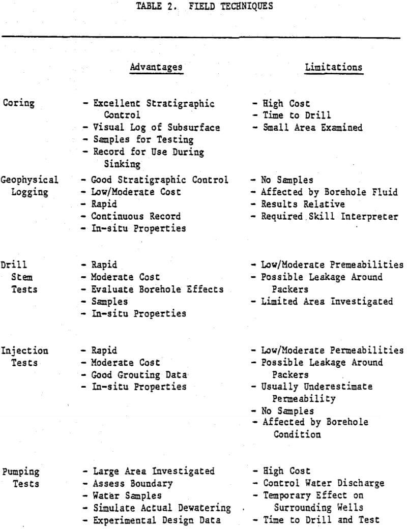
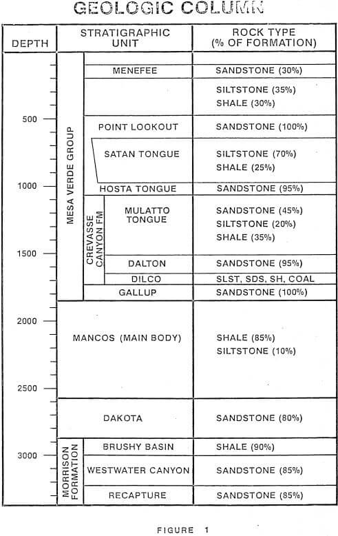
A number of field methods are employed to locate potential waterbearing zones and to estimate their water yield to the shaft. As in all engineering studies, a balance between costs and expected results must be maintained. Field methods can be divided into two broad categories, direct and indirect. Direct methods involve coring, in-hole testing, and laboratory testing. Indirect methods include geologic mapping, preparation of cross sections, and geophysical logging. Direct methods generally produce more accurate and reliable results but also cost more. Table 2 compares some of the advantages and disadvantages of the various field methods in general use.
The results of the field program must allow a reasonable estimate of the parameters necessary to calculate: 1) the hydrostatic head in the shaft area, 2) anticipated inflow rates with time, and 3) the ground water velocity across the shaft area. Specifically, the following data must be known:
- Location, depth, thickness and extent of known aquifers and confining beds.
- Tranmsmissivity and storage coefficient of aquifers and confining beds.
- Whether aquifers are under water table or artesian conditions.
- Head relationships.
- Location and attitude of faults.
- Nature of fault zones (impermeabile barriers or conduits for water movement).
- Position of proposed shaft within the areal hydrologic system (recharge, discharge, or horizontal flow area).
- Water quality.
Predicting Water Inflow
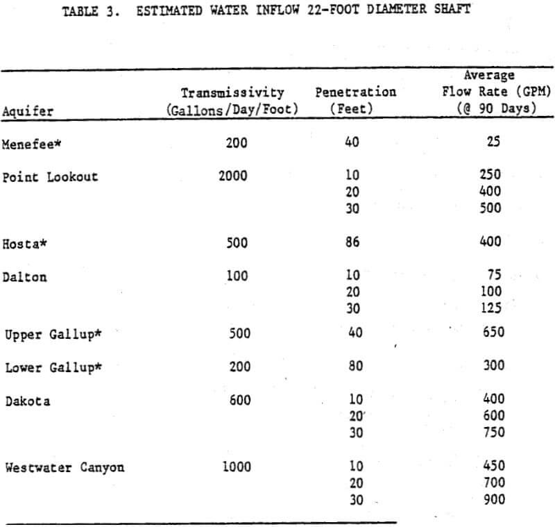
Relative to the larger problem of mine dewatering, estimates of probable water inflow to a shaft are simplified by the fact that a shaft is essentially a large diameter well and there is an extensive body of theory governing flow to wells. Once the above design parameters for each potential water-bearing horizon are known, the approximate water inflow at any given time can be estimated with the following equation:
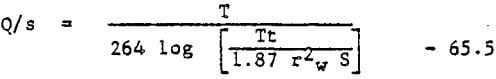
where rw is the radius of the shaft, in-feet, S is the storage coefficient, T is the transmissivity, in GPD/FT, t is the time after pumping started, in days. This equation yields the theoretical full-penetration specific capacity (Q/s) of the shaft in gallons per minute per foot of drawdown (GPM/FT). The inflow rate is found by multiplying the available drawdown (s) by the specific capacity.
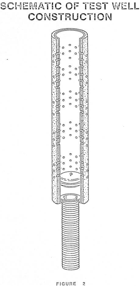
Depending upon the type of shaft construction and the aquifer thickness, a given water-bearing horizon may not be exposed throughout its entire thickness at any given time. Such would be the case for a thick aquifer where the shaft is excavated 10 to 20 feet ahead of the lining. In this case, the theoretical full penetration specific capacity would overestimate the actual quantity of water.that will flow into the shaft. If the amount of partial penetration at any given time is known, the reduced specific capacity can be calculated from the following equation:
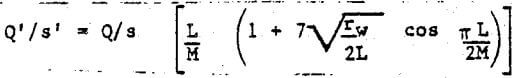
where Q’/s’ is the specific capcity of the partially penetrating shaft, L is the length of the open hole, and M is the aquifer thickness. The adjusted specific capacity (Q’/s’) is then multiplied by the total available head to estimate water inflow. This equation is valid only under near steady state conditions.
Selection of Water Control Method
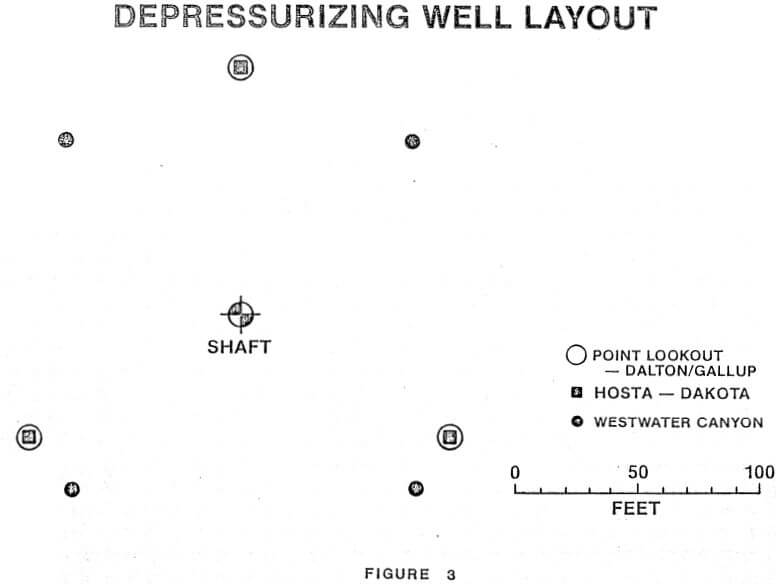
Once a determination is made that water control techniques will be required, it remains to select the optimum control system. Common systems include installation of water rings, sump pumping, grouting, freezing, and pumping from deep wells outside the shaft perimeter.
It is not the purpose of this paper to compare advantages and disadvantages of various water control methods. However, a few general observations can be made.
Collecting water that flows into the shaft and pumping it to the surface is the most time honored method of water control. Water rings can be installed as the shaft liner advances allowing for better control of the inflowing water. This is probably the least cost method, however, it is not effective where large water inflows, especially in poor ground, are encountered.
Grouting is probably the second most popular method. Water-bearing zones can be grouted from the surface or from various levels within the shaft as it advances. In addition to reducing rock permeability, grouting can also increase strength in weak ground. Grouting is not without its difficulties, however. It is as much an art as a, science and works best when there are well defined isolated fracture systems that contribute most of the water. Grouting may be less effective in fine-grained materials or in fractured areas where clay may be present along openings.
Freezing is a technique that has gained popularity in soft ground areas. Unlike grouting, freezing is undertaken from the surface and may require relatively deep very closely spaced, holes ringing the perimeter of the shaft. In some cases, the time to freeze the ground may be a factor in considering this technique. It is generally recognized as one of the most expensive methods of water control.
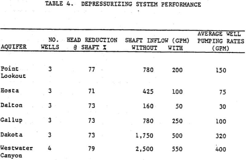
Deep dewatering wells can be used to reduce hydrostatic pressures and water inflow races. Wells are often used in conjunction with sump pumps and grouting. In many cases, dewatering wells will only reduce water inflow into the shaft, not completely stop it. Wells are only effective when there is, a continuous, sufficient flow of water to allow continuous pumping.