
General Procedure for IsaMil Signature Plot
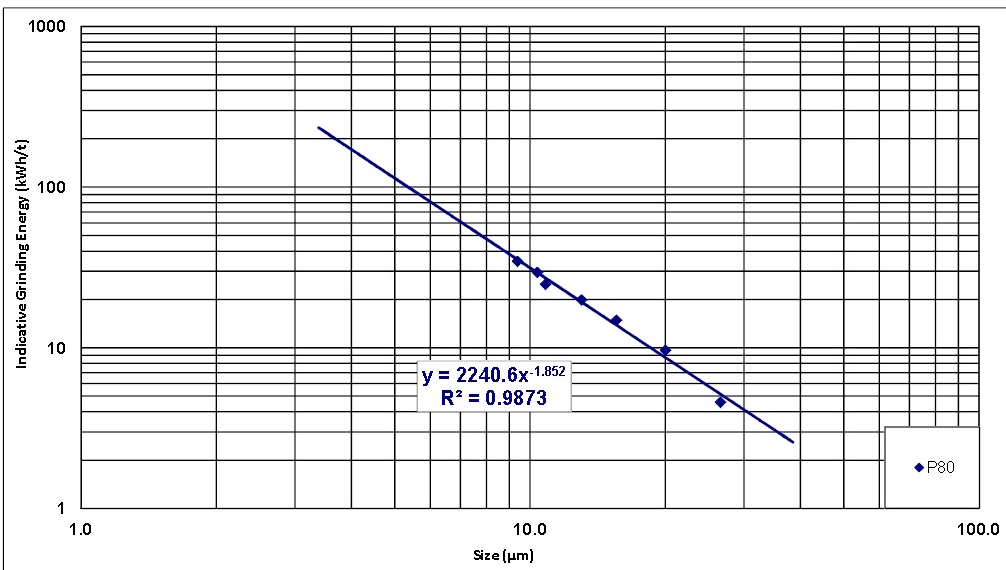
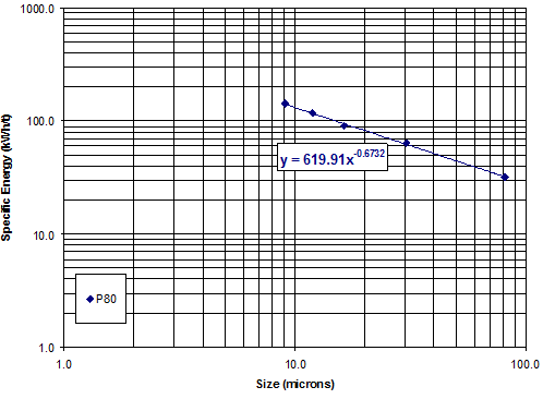
The relationship between product size and energy input remains constant during scale-up of IsaMill™ technology. As the diameter of a particle is halved, the surface area of its progeny is doubled. Within reasonable reduction ratios, the log of size plotted against the log of energy produces a straight line. This line can be extrapolated within the limits of media efficiency and viscosity. This plot is referred to as a signature plot, and is unique to the ore, pulp conditions and media selected. An example of a signature plot is shown below. This data is used for mill sizing so its accuracy is of utmost importance.
Purpose
The development of the signature plot is used to design full scale IsaMill’s. Most full scale installations have been designed from a signature plot developed in a 4 litre laboratory continuous mill. The 4 litre test must reflect the media and pulp conditions planned for full scale operation, or full scale design can be based on the most efficient signature plot developed during test work.
Equipment
1 x 4 litre IsaMill™ (or LME4 Netzsch mill)
1 x positive displacement feed pump
2 x agitated tanks (approx. 50 litres)
1 x watt-hour meter
1 x mill shaft speed indicator (rpm)
Sample containers (small)
Laser particle sizer
Media Charge for the IsaMill™ 2.5L
Pan for collecting and weighing the media charge
Stop Watch/Timer
Procedure
Part 1: Mill Warm-up and No Load Power (NLP) Test
- Turn on cooling water to the gland seal.
- Ensure adequate sealing fluid level and pressure.
- Run the IsaMill™ empty (no water or media) for 5-10 minutes to warm up the bearings and seal.
- Then proceed to run the mill empty at 1500rpm for an additional 10 minutes and measure the cumulative power draw – using the watt-hour meter (Wh) and stop watch.
- From the time and total energy values, the no load power draw can be calculated.
Part 2: Initial Pass
- After weighing the solids, 15 kg dry solids equivalent, add enough water into one tank to make up the desired pulp density (unless otherwise determined this should be ~50% solids). Then with the agitator on and the tank recirculating via the pump, gradually add the solids to the tank.
- Ensuring that the feed tank is recirculating via the pump, adjust the feed pump to the desired flow rate (~ 2 to 3 l/min is typical) to achieve approximately 10 kWh/t energy input (for once slurry is directed to the mill). The flowrate of the slurry is inversely proportional to the product size due to its effect on the residence time and energy (kWh/t) input. Therefore a lower flowrate should be used to obtain a longer residence time and higher energy input and hence a finer grind size.
Note: If a relatively coarse product size is desired, the first couple of passes through the mill should be carried out at high flowrates to achieve coarse points on the signature plot curve and then the flow rate can be reduced as required to increase the energy input and achieve finer product sizes. - Take at least 2 samples of the feed for size analysis. Take a third sample (~100 mL) for % solids determination (measure wet and dry weight of sample).
- With the mill off (and locked out or tagged if applicable) add 2.5 litres (bulk) of MT1 media to mill chamber (also 2.5 litres if using sand). Measure the weight of media before adding. Refer to appendix 1 as a guide to selecting media size though it is recommended to consult with Xstrata Technology for particular feeds being tested. Note that the mill can momentarily switched on to distribute media within the mill during the media addition as required.
- Zero the cumulative Power meter (Wh) or make note of the starting value.
- Change the valves to take the feed slurry out of recirculation and direct the flow through the mill.
- Immediately start the mill at 1500 rpm (nominal) and start the timer.
- Once slurry has been exiting the mill for 15 seconds direct the mill product hose into the second (empty) tank.
- Turn on second tank agitator as soon as level builds up in tank.
- At about the midway point of the pass (i.e. when the two tanks have about equal level):
a. Take 2 product samples for size analysis
b. Measure and record the flow rate of product.
c. Measure and record the pulp density of product (calibrated Marcy scale)
d. Record the product temperature, feed pressure and pump speed. - Continue to grind until the feed tank is empty.
- As soon as the feed tank is empty, stop the mill, stop the timer and change the valves so the product tank (full tank) is in recirculation. Ensure sufficient agitation of the tank.
- Record the time taken for all the slurry to be treated through the mill and the total power consumption (Wh).
- If trying to achieve a target grind size, it is recommended that particle size analysis be carried out after each pass to determine the grind size achieved. Otherwise it is more time efficient to carry out all particle size analysis at the completion of the required number of passes.
Part 3: Second Pass and all subsequent Passes
- Change feed pump suction valving so the full product tank (in recirculation) becomes the feed tank.
- Keep the mill product hose depositing slurry into the feed tank.
- Adjust the feed pump flow rate if required.
- Zero the cumulative Power meter (Wh) or make note of the starting value.
- Change the valves to take the feed slurry out of recirculation and direct the flow through the mill.
- Immediately start the mill at 1500 rpm (nominal) and start the timer.
- Once slurry has been exiting the mill for 15 seconds (since the mill is full, this should happen almost immediately) direct the mill product hose into the second (empty) tank.
- Turn on second tank agitator as soon as level builds up in tank.
- At about the midway point of the pass (i.e. when the two tanks have about equal level):
a. Take 2 product samples for size analysis.
b. Measure and record the flow rate of product.
c. Measure and record the pulp density of product (calibrated Marcy scale).
d. Record the product temperature, feed pressure and pump speed.
e. During the entire test, take at least 2 other samples (~100 mL) for % solids determination (e.g. pass 3 or 5). Note that it is important to take one of the samples on the last pass (pass 5 in most cases). - Continue to grind until the feed tank is empty.
- As soon as the feed tank is empty, stop the mill, stop the timer and change the valves so the product tank (full tank) is in recirculation.
- Record the time taken for all the slurry to be treated through the mill and the total power consumption (Wh).
- Repeat the above steps until the required product fineness or energy input is reached. Usually 5 passes is recommended but more may be required to grind to the target size. Ideally the target size should fall around the middle of the signature plot.
Part 4: Test completion and Second No Load Power Draw (if required)
- At the end of the test, sometimes a media washout is done. This involves adding water to the feed tank and pumping it through the mill while it is running. Note that it is important for the media wear calculation to record the time taken and the power consumed (Wh) for the washout stage.
- Clean and empty mill. Care must be taken to not spill media.
- Collect all the media, screen fine solids from the media and check for coarse solids in the media, dry the media in the oven overnight and then weigh the end media charge.
- The end dry media charge weight will be used to calculate media consumption (note loss of any media during cleaning can have a significant impact on the media consumption value and so should not be reported in such circumstances)
- If required, run the mill empty at 1500rpm for 10 minutes and measure the cumulative power draw – using the Power meter (Wh) and the stop watch.
- This number is used to determine the no load power draw (compare with the initial NLP).
Results
- Measurements to be taken for each run
Density (kg/l)
Sizing (feed and each product) – measured using the generic Mie theory model (OHD presentation model) unless otherwise specified. The P80 in µm is the standard sizing reference. Where needed for specific projects, the P98 may be reported though care must be taken to achieve an accurate measurement. Note that there is an option in the IsaMill Example Report (see appendix 3) drop-down menu to include the P98.
For sizing ores with high specific gravity (e.g. iron ores which have a specific gravity of ~4.5 – 5) screening with either cyclosizing or micro-screening is recommended.
The full particle size distribution for each pass should be reported (see Example of IsaMill Report)
Flow rate (sec / litre)
Power Draw (Wh) – difference from when the mill is turned on to when it is stopped
Time for run
Product temperature and feed pressure - Calculations:
Calculate the average t/h and gross power for each pass.
For each pass, subtract the no-load power from the average gross power to get average net power.
Divide the average net power by the t/h for each pass to get net energy input (also known as specific energy, or absorbed energy).
Plot size on log x-axis, against net energy on log y-axis (data should approximate straight line). Selected size data should be relevant to the application (e.g. P98, P80, P50 etc).
Use a power equation to fit a line through the data for interpolation (e.g. y = a.x –b).
Find the required energy input for the target grind size (or vice versa).
Plot full size distributions for each pass on one graph to illustrate size reduction characteristics for the IsaMill. - Note that each site will be required to run a Quality Assurance Signature Plot test on a known sample supplied by Xstrata Technology once a year to ensure Xstrata Technology’s test standards are maintained.
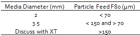
Appendix 1 – Media Size Selection
The following can be used as a rough guide to selecting media size. Note that the material’s hardness may also be a factor in media size determination. Keramax MT1 is the media of choice for signature plot testing but other media types can be tested at the clients’ request. Caution – Do not blend different media types together for signature plot testwork.
A conditioned media charge (or new graded charge) should always be used, refer to Appendix 2 for Charge Preparation and Maintenance.
Appendix 2 – IsaMill™ Charge Preparation and Maintenance
Ideally conditioned charges should always be used when conducting IsaMill™ testwork. For new testwork sites or new charge top sizes, conditioned charges do not exist and are only created over time (and many tests) and in these cases graded charges (which can become conditioned charges) are substituted.
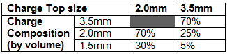
The two recommended Keramax MT1 ceramic graded charges and their bead size composition is shown below. The graded charge size for Keramax MT1 for the M4 IsaMill™ is 2.0 litres.
Once the graded charge is made up the charge should be weighed. This weight is the charge starting weight and will be the make up weight for the future for this charge.
The new graded charge should be milled in water for 20 minutes to prepare it for use with slurry. Note that accurate wear data may not be attainable from the first couple of signature plot tests using a fresh media charge due to the nature of the new media.
Maintenance of this ceramic graded charge needs to occur after every test. To maintain the IsaMillTM charge once a test has been completed the charge should be removed from the mill, cleaned (by washing any slurry/dirt off) and dried. The test finish charge weight is recorded and the charge is “topped-up” to the charge starting weight using Keramax MT1 top size ceramic beads.
The consumption of Keramax MT1 is very low so if multiple tests (2-3) are completed in one day the charge can “topped-up” at the completion of a day’s testing.
“Topping-up” the charge with top size ceramic beads over time will move the IsaMillTM charge from a graded charge to a conditioned charge.
Maintenance for Natural Media charges (i.e. sand, slag etc) is similar to ceramic charges. Although the initial charge is not graded the charge starting weight must be recorded. At the completion of each test the charge is cleaned, dried and weighed. The charge should be “topped-up” to the initial charge starting weight by adding “fresh” natural media.
Appendix 4 – IsaMill™ – Malvern Laser Sizer Procedure
- Flush Malvern with full beaker of clean water.
- Check glass slide for particles, wiping clean if necessary.
- Prepare sizing sample-
a. Fill a clean 1L beaker with 600 ml of water
b. Place baffles in beaker
c. Empty entire sizing sample container into beaker
d. Begin mixing with desktop mixer. Note: Mixer should be as close to the bottom of the beaker as possible and the slurry should appear turbulent, not centrifuging - Once the Malvern is clean open a new file in the computer program, naming it accordingingly. Replace the beaker of water used for flushing the Malvern with a new one filled with 800ml of clean water.
- Begin the program steps to align the laser and start the measurement.
- Note the obscuration level with clean water, 0-0.2 is acceptable and the sizing analysis can begin. More than this and the machine needs further cleaning.
- Using pipette draw slurry from the bottom of the mixed beaker.
- Empty slurry from the pipette into the Malvern beaker. Target an obscuration of 15.
Note: As each pass through the IsaMill results in a finer product less volume of slurry will be required to maintain an obscuration of 15. An adjustable pipette will be more suitable for making these small adjustments than regular disposable pipettes and will result in less segregation caused errors from material either left in the pipette or multiple slurry samplings being necessary with the regular pipette. - When the measurement is done remove the beaker and replace with one filled with clean water, begin flushing the system. Some Malvern sizers will have an automatic cleaning system. If available utilize this.
- Clean individual beakers, baffle, mixer and pipette.
If all Malvern measurements are conducted after the M4 test, start with the last pass, moving then to each successively coarser sample to minimize the effects of any coarse contamination from one sample to the next.
Use Malvern recommended calibration samples and contact XT with any concerns over machine performance or suitability.
Appendix 4 – Example of Spreadsheet Report
Please note that comments have been added to some of the cells and can be accessed by clicking on the red tabs in the corner of these cells. Further, different options for the spreadsheet are available and can be selected from the drop down menus available in cells R3 to R6.
Appendix 5 – IsaMill™ – Job Safety Analysis (Sample)